
INTRODUCTION
Sandwich structures initiated in the 20th century are contemporary intensively developed and improved. Carrera [1] presented a detailed review of theories used in analytical modeling of multilayer structures, in particular Zig-Zag theory, taking into account 138 publications, including three from the 19th century. Magnucka-Blandzi and Magnucki [2] developed an analytical model of a simply supported sandwich beam with symmetrically varying mechanical properties of the core at its depth and determined the critical load of this beam. Based on the formulated optimization criterion with consideration of the critical load, the dimensionless effective parameters of the example beam were determined. Carrera and Brischetto [3], taking into account selected important articles on modeling layered structures, pointed out the advantages and certain imperfections of the theories used, presenting five comparative problems. They identified two main sources of error: geometric parameters (the length-to-thickness -ratio LTR) and mechanical parameters (the face-to-core-stiffness-ratio FCRS). Demasi [4] presented an extension of the generalized unified formulation (GUF) to the theory of higher order shear deformation considering thick-layer structures, taking into account the Advanced Higher Order Shear Deformation Theory and a fourth-order fully Zig-Zag theories. Grygorowicz et al [5] studied the sandwich beam buckling problem analytically and numerically with FEM. The mechanical properties of the core of this beam varied symmetrically along its depth. The analytical model of this beam takes into account linear and nonlinear shear deformation theory. Detailed critical load tests were carried out on sample beams. Sayyad and Ghugal [6] presented a detailed, comprehensive review of publications on bending, buckling and free vibration of sandwich beams, taking into account 515 works, from the 18-th century to the present, related to these problems. Kędzia and Smyczyński [7] analytically investigated the buckling problem of a rectangular polyethylene sandwich plate subjected to a magnetic field. The analytical model of this plate was developed taking into account the the “broken line” theory. Critical loads and dynamic equilibrium paths for example plates were determined. Paczos et al. [8] studied analytically and experimentally the three-point bending of simply supported sandwich beams with an individual structure of the honeycomb core. This beam was manufactured using additive technology, and the elastic modulus of the core varied along its entire length. The test results determined using these two methods were compared with each other. Magnucka-Blandzi [9] developed an analytical model of a seven-layer beam with three-layer cladding. The central core and cladding cores are wavy structures. Detailed deflection and buckling tests were performed for the translated family of beams. Marczak [10] presented an analytical study of the vibration problem of sandwich panels with periodic facings, taking into account the broken line hypothesis. He examined the vibration problems of this plate taking into account two tolerance models and, based on the analysis of the calculation results, he indicated an easier and more precise model that contains fewer governing equations with fewer coefficients. Magnucki et al. [11] studied analytically and numerically FEM the bending problem of a simply supported homogeneous beam with a bisymmetric cross section under a generalized load. The analytical model of this beam was elaborated with consideration of the classical shear stress formula – called the Zhuravsky shear stress. Detailed calculations of the maximum deflection of the beam with sample cross sections were carried out using these two methods and their results were compared with each other. Icardi and Urraci [12] developed a generalization of physically-based fixed degrees of freedom 3-D zig-zag theories. The aim of this work was to prove that the choice of global and layerwise functions is immaterial whenever coefficients are recalculated exactly (via symbolic calculus) by the enforcement of interfacial stress continuity, boundary conditions and equilibrium in point form, as prescribed by the elasticity theory. Sharei et al. [13] experimentally and numerically investigated the impact of low speeds on sandwich panels with a foam core reinforced with short hybrid fibers. They experimentally demonstrated a significant impact of core reinforcement with carbon, aramid and carbon-aramid hybrid fibers on the Young's modulus value from 100 to 180 percent. FEM numerical tests confirmed the experimental results, the differences amounted to approximately 9.1 percent. Montazeri and Safarabadi [14] conducted comparative tests on the mechanical properties of composite laminates to demonstrate the influence of hybridization of cut glass fibers and kenaf fibers of their core. They determined that the kenaf core laminate had the highest dent resistance and the best properties due to the energy absorbed. Moreover, the performed FEM numerical tests showed quite good agreement with the experimental results. Magnucki et al. [15] developed three analytical models of a sandwich beam and analytically and numerically FEM studied the bending, buckling and free vibration problems of this beam. Magnucki [16] presented the individual nonlinear deformation theory and its application to analytical modeling of homogeneous beams, sandwich beams and functionally graded beams. Lewandowski and Litewka [17] analytically presented the problem of harmonic vibrations of laminated plates in the von Karman geometrically non-linear regime, taking into account the refined zigzag theory. Montazeri et al. [18] presented experimental and numerical FEM studies of three-point bending of beams with six honeycomb structures and different Poisson's ratios obtained using 3D printing technology. They demonstrated that four novel honeycomb structures, designed by hybridizing hexagonal and re-entrant units, outperformed standard conventional honeycomb structures in terms of load-bearing capacity. Montazeri et al. [19] investigated experimentally and numerically in FEM the performance of hexagonal and concave honeycombs additively manufactured based on polylactic acid and thermoplastic polyurethane, subjected to three-point bending. Conventional and auxetic cellular structures filled with polyurethane were created using 3D printing technology. The obtained research results indicated positive performance of foam-filled thermoplastic polyurethane based auxetic structures. Magnucki and Magnucka-Blandzi [20] developed analytical model of an asymmetric sandwich beam with consideration of the classical shear stress formula, called the Zhuravsky shear stress, and analytically studied the bending problem of this beam under uniformly distribute load along its length. Magnucki et al. [21] analytically and numerically studied the banding problem of a sandwich beam with stepped layers thicknesses. The effect of this thickness stepped on the beam deflection is analyzed.
The subject of the work is a sandwich beam with a core of an individual structure, the influence of which on the deformation shape of a planar cross-section is special. The main purpose of the work is to analytically determine such a structure of this core that the deformation shape of the planar cross-section of this beam will be exactly in accordance with the “broken line” theory.
ANALYTICAL MODEL OF THE SANDWICH BEAM
The cross section of the typical sandwich beam of total depth h, faces thicknesses hf, core thickness hc and width b is shown in Fig. 1.
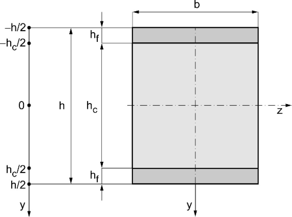
The Young’s modulus of successive layers is as follows:
– the upper face-sheet: − 1/2 ≤ η ≤ − χc ⁄ 2
– the core: − χc ⁄2 ≤ η ≤ χc/2
– the lower face-sheet: χc ⁄ 2 ≤ η ≤ 1 ⁄ 2
The general theoretical deformation of a planar cross section without shear effect in the faces of this beam, according to the paper [15], is shown in Fig. 2.
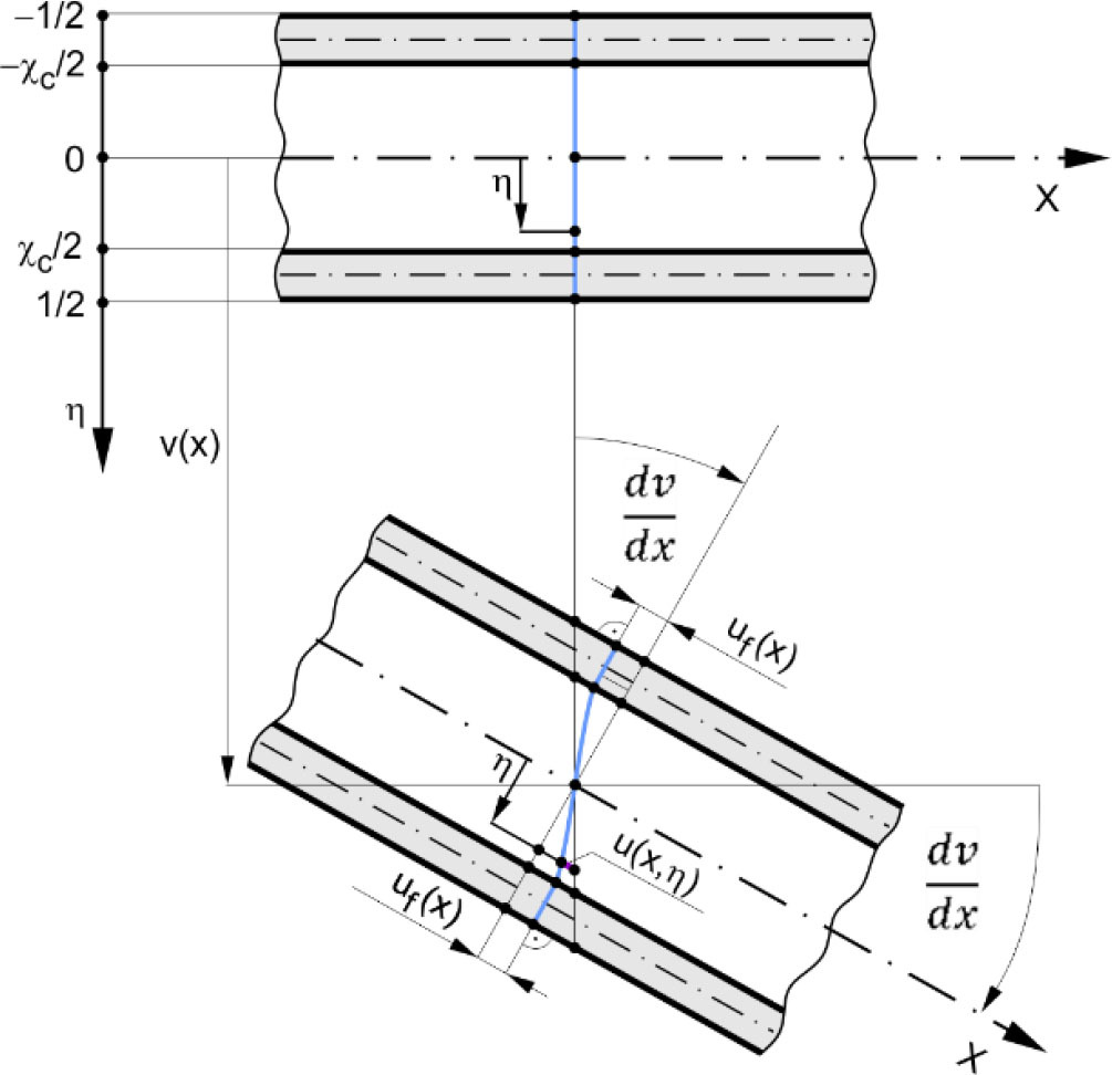
Considering Fig. 2 longitudinal displacements, strains and stresses in successive layers are written in the following form:
– the upper face-sheet: − 1⁄2 ≤ η ≤ − χc ⁄ 2
– the core: −χc ⁄2 ≤ η ≤χc ⁄ 2
– the lower face-sheet: χc⁄2 ≤ η ≤ 1/2
where: ψf(x) = uf(x)⁄h – dimensionless displacement function,
This dimensionless deformation function
Taking into account the papers [15] or [16], the selected part of this beam cross section is shown in Fig. 3.
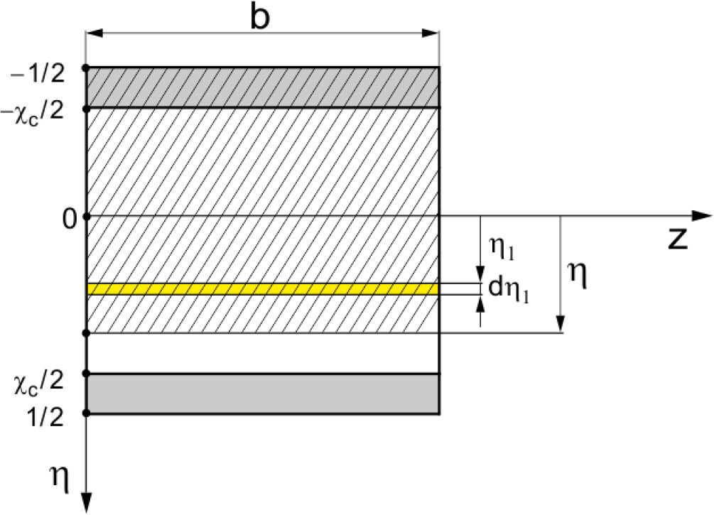
The first moment of the hatched area of the beam cross section (Fig. 3) with consideration of the Young’s modulus is as follows:
whereEquating the shear stress (11) to the classical shear stress formula (15) with consideration of the expression (16), after transformation, the derivative and the dimensionless function of the nonlinear deformation of a planar cross section of the core are obtained in forms:
where C0 – constant.This function according to the “broken line” theory, described in the paper [15], satisfies the following conditions:
therefore, the constant C0 is determined form the conditionBased on the expression (19), with consideration of the first condition (21), the following equation is formulated
Differentiating this equation and after simple transformation, the following differential equation is obtained
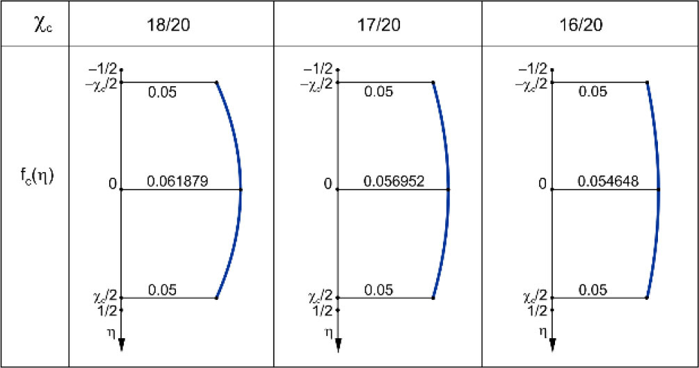
The solution of this equation is the subject function of variability of Young’s modulus along the thickness of the core in the following form
This function satisfies the condition fc(∓ χc⁄2) = ec.Thus, the longitudinal displacements, strains and stresses of the core are as follows:
– the core: − χc ⁄ 2 ≤ η ≤ χc ⁄ 2
THREE-POINT BENDING OF THE SANDWICH BEAM
The bending moment, according to its definition, for the subject sandwich beam is of the form
where:Substituting the expressions (6), (14) and (28) into the above expression (31), after integration one obtains the equation
where dimensionless coefficients:The elastic strain energy
where:Substituting the expressions (5), (13), (27) and (28) into the above expression (33), after integration the elastic strain energy is of the form
where dimensionless coefficients:The work of the load
where T(x) – shear force.Taking into account the principle of stationary total potential energy δ(Uɛ, γ − W) = 0, two differental equations of equilibrium of this sandwich beam is obtained in the following form:
The equations (32) and (36) are equivalnet, then, equations (32) and (37) are fundamental in the beam bending studies. Thus, after simply transformation of these two equations, the one differential equation of the form is obtained
whereThe three-point bending problem of this sandwich beam is analyzed in detail. The scheme of the beam of length L is shown in Fig. 4.
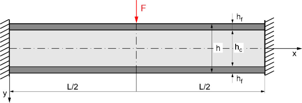
The scheme of the left end-part of this beam with reactions is shown in Fig. 5.
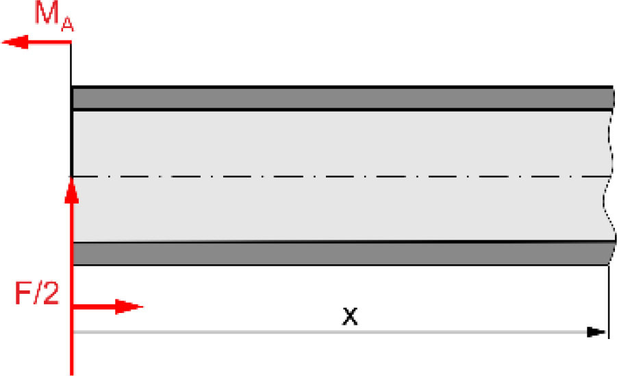
Thus, the shear force and the bending moment in the left part of this beam (0 ≤ x ≤ L⁄2) are as follows:
Consequently, the differential equation (38) with consideration of the expression (39a), in the dimensionless coordinate ξ = x⁄L, is in the following form
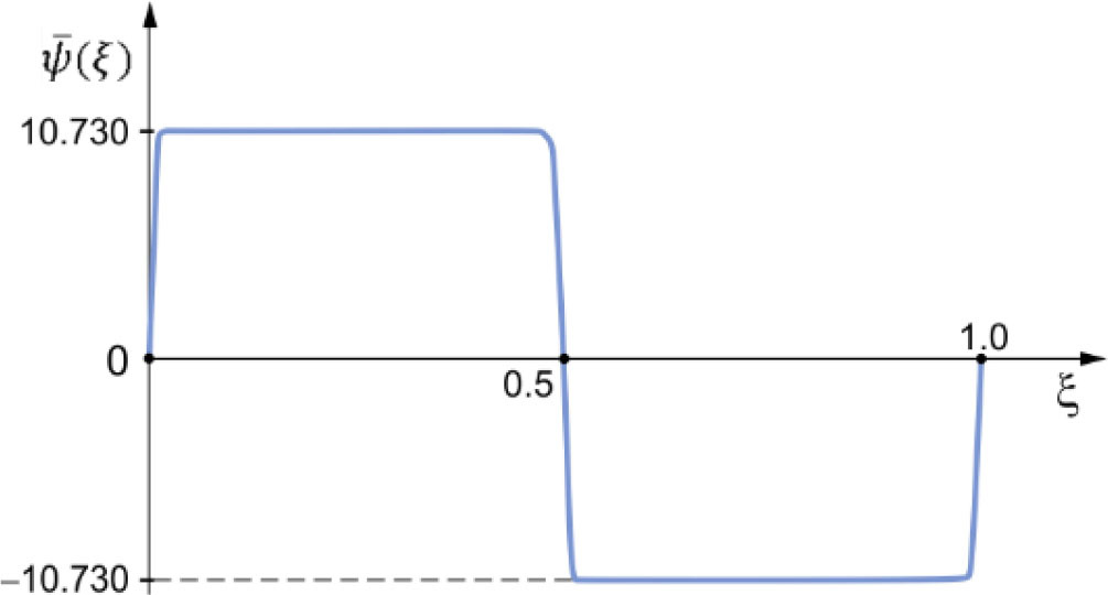
where λ – relative length of the beam.The solution of this differential equation for the left part of this beam (0 ≤ ξ ≤ 1⁄2) is as follows
whereThis function satisfy following conditions: ψ̄f(0) = 0 – clamped end, and ψ̄f (1⁄2) = 0 – middle of the beam.
The equation (32) with consideration of the expression (39b), in the dimensionless coordinate ξ = x⁄L, was written in the following form
where: v̄(ξ) = v(ξ)⁄L – relative deflection of the beam, M̄A = MA⁄(FL) – dimensionless reaction moment.This equation after integration is in the form
where the integration constant from the condition dv̄ ⁄ dξ]0 = 0 is equal to zero C3 = 0, and the dimensionless reaction moment from the condition dv̄⁄dξ]1⁄2 = 0 is equal M̄A = 1⁄8.Consequently, integrating this equation and taking into account the function (41) and the boundary condition v̄(0) = 0, one obtains the function of the relative deflection of the beam
where andThus, the relative maximum deflection of the beam is as follows
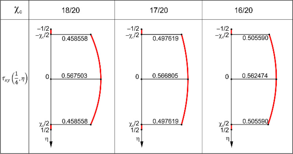
where the dimensionless maximum deflection and the shear coefficientThe shear stresses (30) in the core with consideration of the expression (41) is in the following form
where the dimensionless shear stressSAMPLE DETAILED CALCULATIONS
Example calculations are carried out for three selected structures of sandwich beam of following data: λ = 15, ec = 1⁄20, v = 0.3, χc = 18⁄20, 17⁄20, 16⁄20. The graph of the dimensionless displacement function (42) for selected structure of sandwich beam χc = 18⁄20 is shown in Fig. 6.
The results of this calculations: values of the constant C0, dimensionless displacement function ψ̄f (1⁄4), shear coefficient Cse, and the dimensionless maximum deflection ṽmax are specified in Tab. 1.
Tab. 1.
The results of calculations of the selected structures of beam
| χc | 18/20 | 17/20 | 16/20 |
| C0 | 0.21375 | 0.29484375 | 0.36 |
| ψ̄f(1⁄4) | 10.730 | 10.997 | 10.915 |
| Cse | 0.248714 | 0.349100 | 0.433171 |
| ṽmax | 56.507 | 45.361 | 39.169 |
Moreover, the results of these calculations regarding the subject function (25) of variability of Young’s modulus along the thickness of the core and the dimensionless shear stress (51) for ξ = 1⁄4 are presented graphically in Fig. 7 and Fig. 8.
CONCLUSIONS
The research presented above, the following conclusions:
– the deformation shape of a planar cross section of a typical sandwich beam is exactly consistent with the “broken line” theory, when the Young’s modulus variable along the core thickness in accordance with the function in the form (25),
– the distribution-graph of the shear stress along the core thickness is non-linear (Fig. 8).