
INTRODUCTION
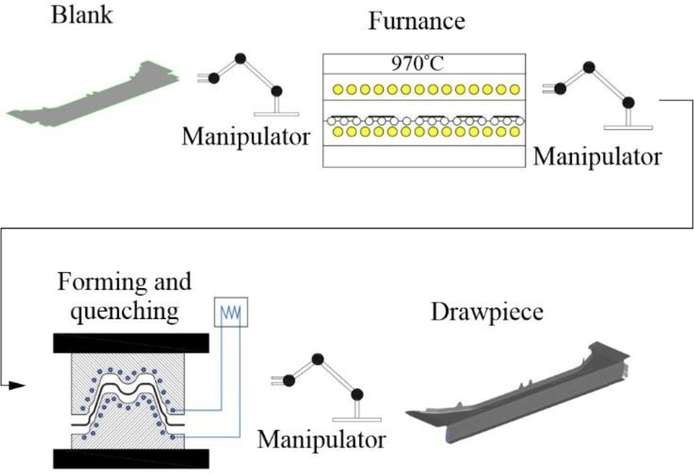
It is desirable that body structures of new generation cars, especially electric ones, have the lowest mass possible [1]. In order to achieve a significant mass reduction, load-bearing components of automotive bodies have been produced for several years using hot stamping technology [2,3]. The components are manufactured from well-hardened manganese-boron steels, such as Usibor 2000 and MBW-K1900 [4–6]. Hot stamping is a process which consists of plastic forming and quenching of a blank heated to the austenitisation temperature in a stamping die. This is illustrated in Fig.1.
After the hot stamping process, the steel structure is a martensitic and can achieve tensile strength reaching 1900 MPa and Vickers hardness exceeding 400HV. This represents a new quality in the production of high-strength drawpieces. Moreover, the technology enables the production of drawpieces with zones of varying thicknesses, and thus with different mechanical properties in these zones [7,8].
The development of a technological process for the production of drawpieces using the hot stamping technology requires each time an individual approach. Although similar products can be distinguished within the group of drawpieces produced using this technology, such as door reinforcement beams, thresholds, A-and B-pillars, etc., the design of the die for each drawpiece is different. This is due to the required distribution of cooling channels in the die, punches and binders, the expected kinematics of the tool as well as the conditions of the process itself. The specificity of a hot stamping process means that the detail should remain in a fixed position throughout the entire process and be formed in a single cycle of the press slider movement.
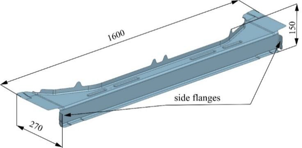
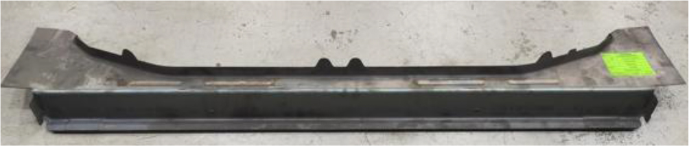
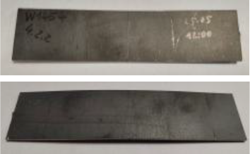
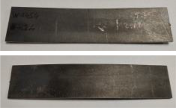
This paper presents steps leading to the development of a hot stamping technology for the rear beam connecting the side members of a passenger car (Fig.2). The beam, with dimensions of 1600 mm x 270 mm x 150 mm, classified as a large-size drawpiece is manufactured from a 1.6 mm thick sheet of MBW-K1900 steel, without coatings. The steel is supplied with the following properties:
After the hot stamping process (forming and quenching), a drawpiece manufactured from this steel exhibits a martensitic structure, which in turn guarantees the strength limit Rm within the range of 1400÷1900 MPa and Vickers hardness of HV>400
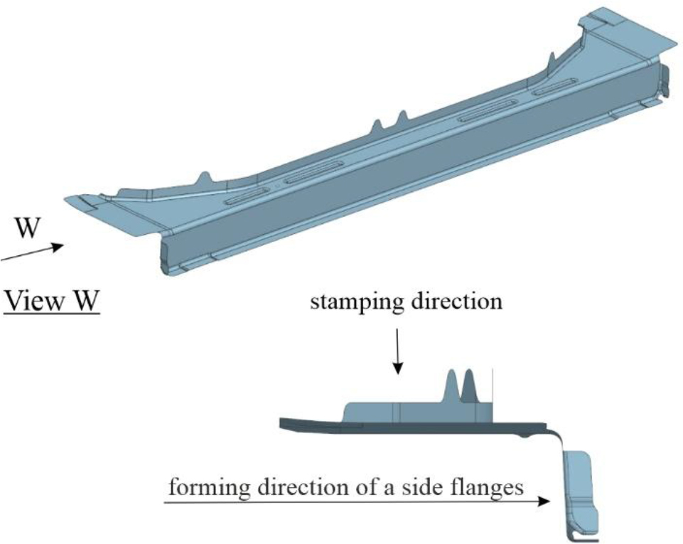
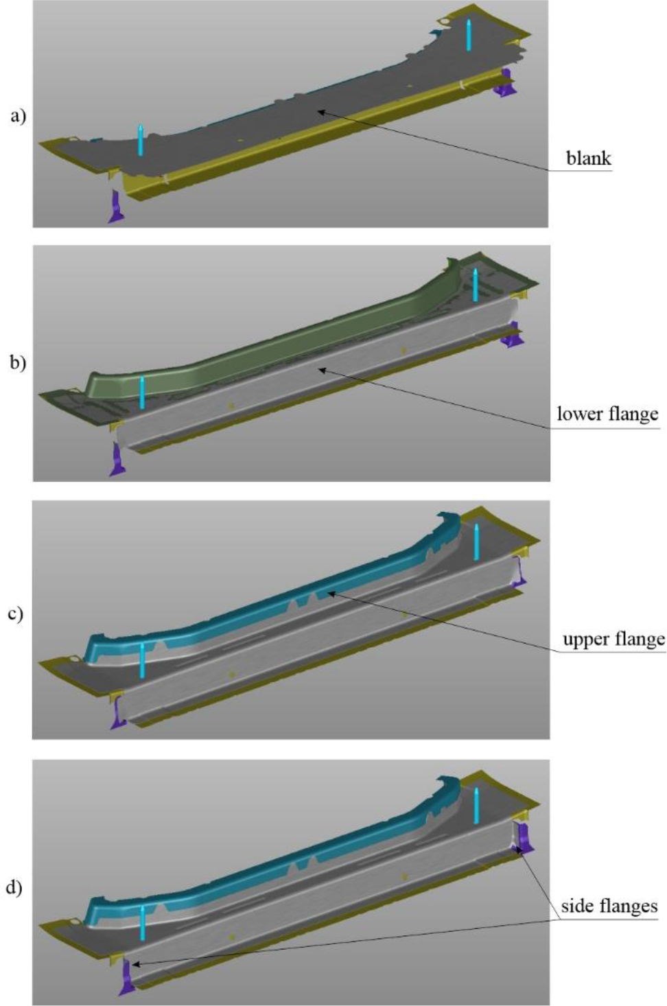
The analysed drawpiece has an non-typical shape in the form of a side flange bent transverse to the main stamping direction (Fig.3). This is an uncommon situation in typical hot-stamped drawpieces, which makes stamping from the main direction difficult. The situation is different in cold stamping processes where stamping from different directions is a common practice. Cam units are then used to change the direction of the tool operation, or the products are rotated on specially designed turntables. In hot stamping processes, such solutions have not yet been used.
The development of assumptions for the design of a stamping die with a complex shape requires a series of computer simulations of the stamping process and tool cooling, in addition to the assessment of the product feasibility [9–11]. Simulations will consider the factors that can affect the stamping process itself and the quality of the final product. In particular, the temperature distribution in the drawpiece and tool will be assessed as well, maximum temperature values, and the proportion of martensite in the drawpiece. A drive system for dies and punches operating from the direction other than the main one will be developed. An actuator will be selected to ensure the appropriate slide speed, stroke and the force required for the formation of side flanges. The simulation of the thermal expansion of dies and punches will facilitate the assessment of the correct selection of tool clearances. This is significant especially when stamping large-size products where drawpiece jamming in the tool is possible. This is caused by thermal shrinkage and hardening stresses that occur during the process [12].
Stamping process of the discussed drawpiece according to the developed technology will be verified in real conditions in the hot stamping process. The quality of the obtained drawpieces will be verified in laboratory tests which will include:
– testing mechanical properties and hardness of a drawpiece by non-destructive and destructive methods,
– hydrogen embrittlement tests,
– evaluation of the microstructure of steel after pressing and quenching,
– testing shape and dimensional accuracy of the finished drawpieces.
. SIMULATION OF THE STAMPING PROCESS
Simulation of the stamping process was performed using Autoform software. A thermomechanical analysis is carried out throughout the simulation until a steady state is achieved. The effectiveness of the cooling system is determined by monitoring the temperature of the drawpiece and the temperature on the working surfaces of the tools. The temperature of the drawpieces at the end of the process should not exceed 250°C. This, together with a minimum cooling rate of approximately 27°C/s for MBW-K1900 steel [13], guarantees the desired martensitic structure of the drawpiece.
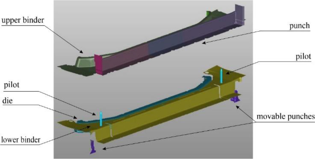
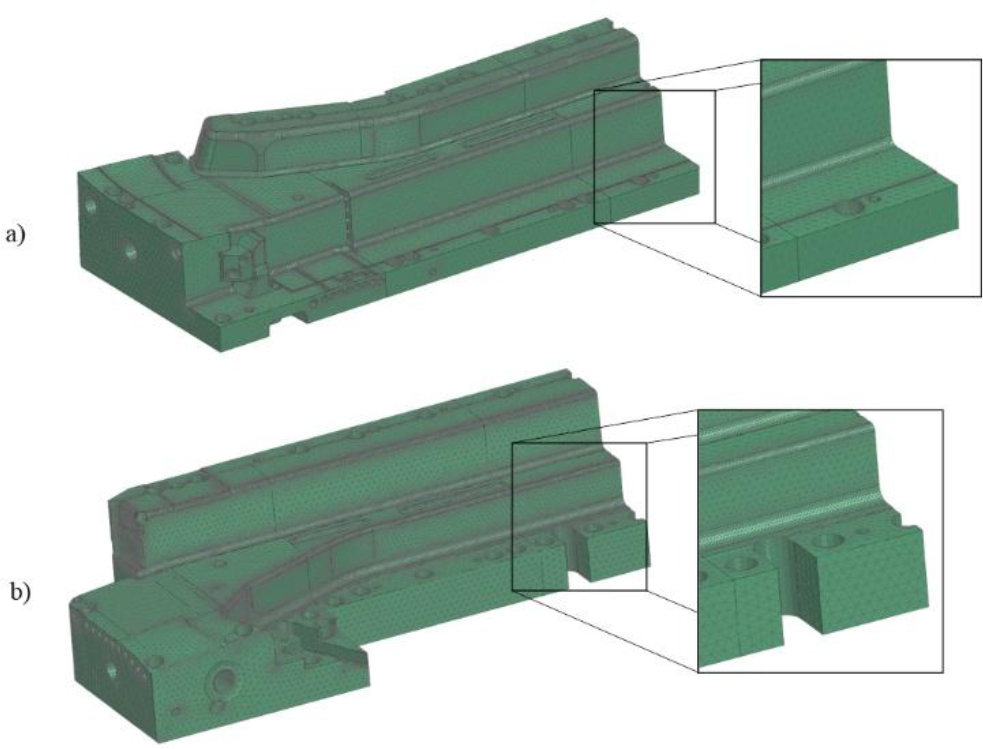
Computer-aided design models of the tools were prepared for the simulation of the process. Based on a three-dimensional model of the drawpiece, working surfaces of the die, binders, and punches were obtained, as illustrated in Fig.4.
Prior to the simulation of the stamping process, tool kinematics and basic process parameters, including tool stroke and stamping speed were selected. Firstly, a correctly cut blank is positioned on the upper surface of the die and the lower binder, and the stamping process is initiated (Fig.5a). The application of the upper binder serves to secure the blank while the punches simultaneously initiate the formation of the initial bottom flange (see Fig.5b). Next, the die and lower binder, mounted on gas springs, move downwards, together with the closed upper binder and punches, forming the top flange (Fig.5c). Afterwards, dies designed for this purpose, attached to sliders with actuators, form the side flanges (Fig.5d). After closing the tool, the press pressure is increased (for improvement of heat exchange between the stamping die and the tool) and the quenching process is initiated. At the end of this stage, the press tool is opened and the tools take their initial position.
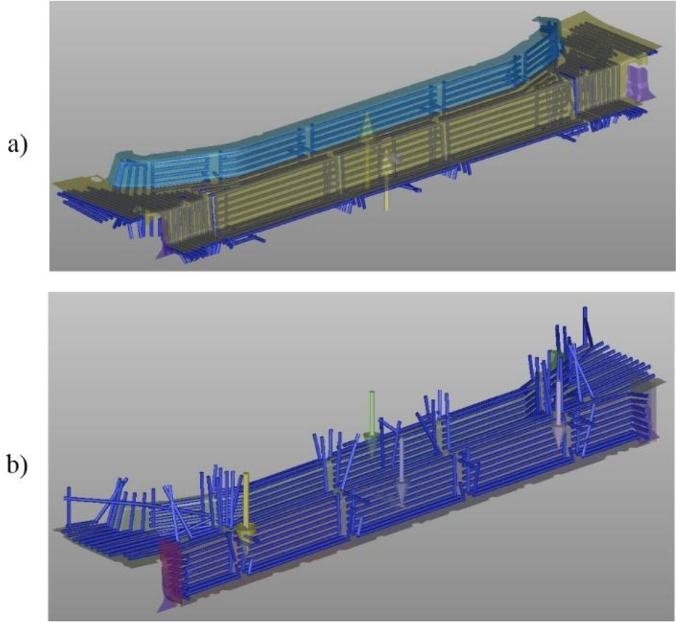
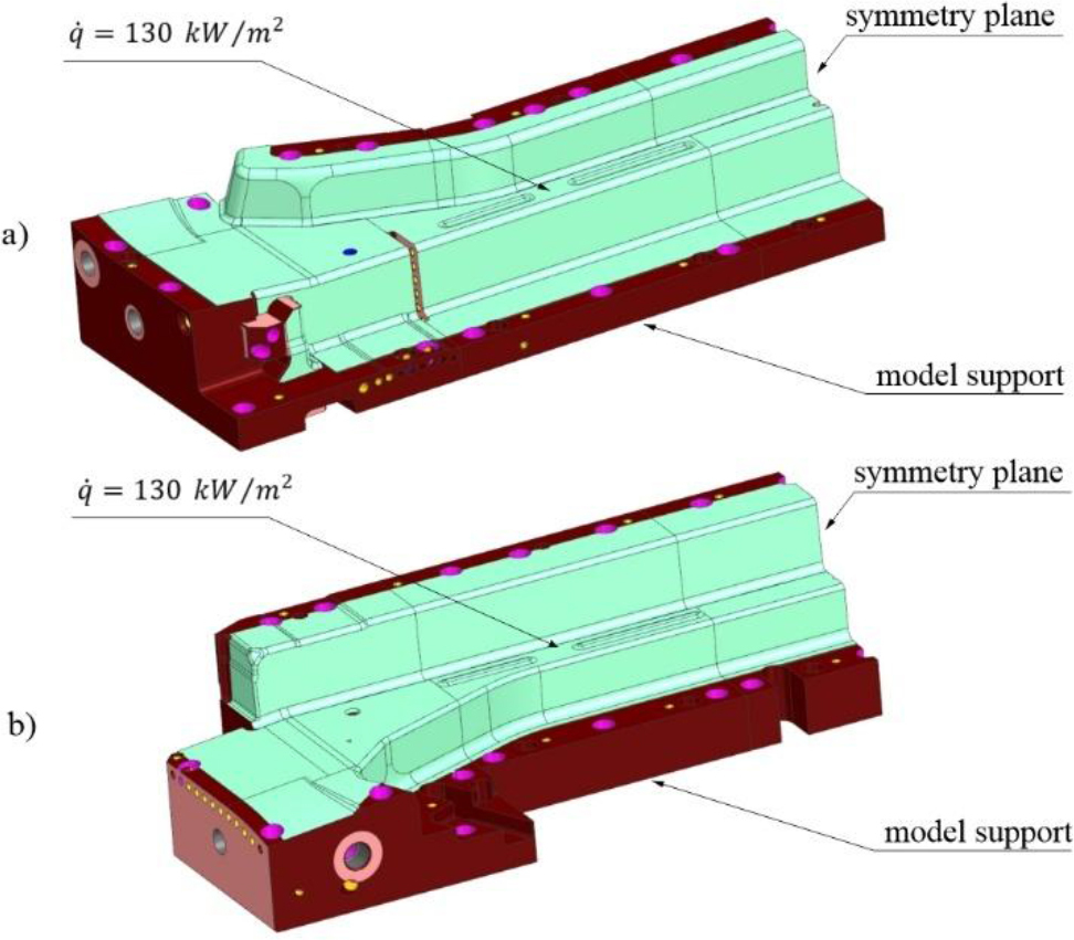
Once the tool kinematics had been established, the parameters related to the cooling process of the die could be determined. In the actual tool, the cooling channels are drilled into individual sections of the tool. In order to simulate the cooling process, the position of the centre lines of the channels was planned and the appropriate diameters were assigned (Fig.6).
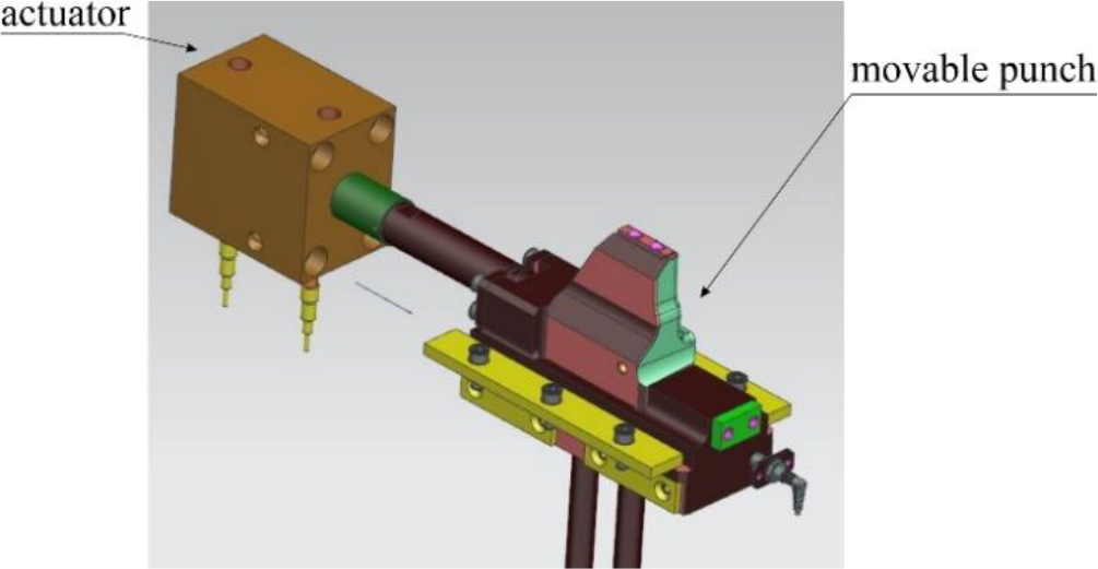
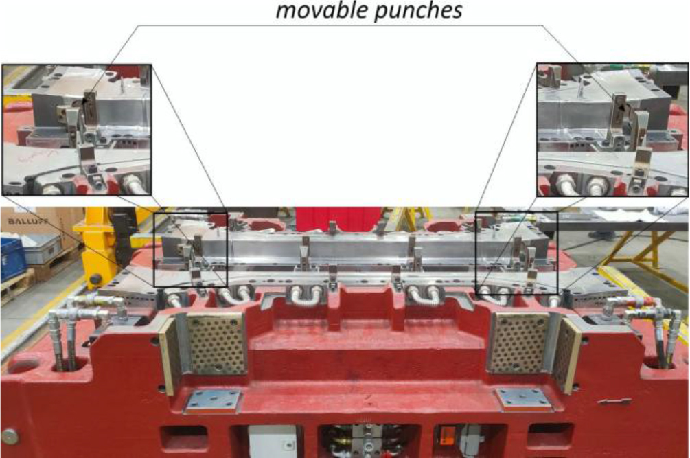
At this point, it is necessary to note a certain aspect related to the modelling of tool cooling channels in the AutoForm package. The latest version of the software does not yet allow the modelling of cooling channels for tools operating in a direction other than the main stamping direction which is a requirement for the designed process (a punch for bending side flanges). The software only permits the assumption of a constant temperature (an initial value of 80°C was assumed for the analyses) on the surface in question. This also serves to illustrate the innovative nature of the proposed solution with a movable punch. Accordingly, simulations of the cooling process of punches for bending side flanges will be carried out after the preliminary design of the tool in the Simcenter FloEFD thermal-fluid analysis module.
The geometric models of the tools and cooling channels were supplemented with the material properties of the drawpiece. In accordance with the design assumptions and with reference to the experience of tool manufacturers, considering suggestions provided by the sheet metal manufacturer, the following was assumed for the process:
– the initial temperature of the blank 810 °C,
– heat transfer coefficient from the tool to the cooling medium 15 mW/mm2K,
– the temperature of cooling medium 20 °C.
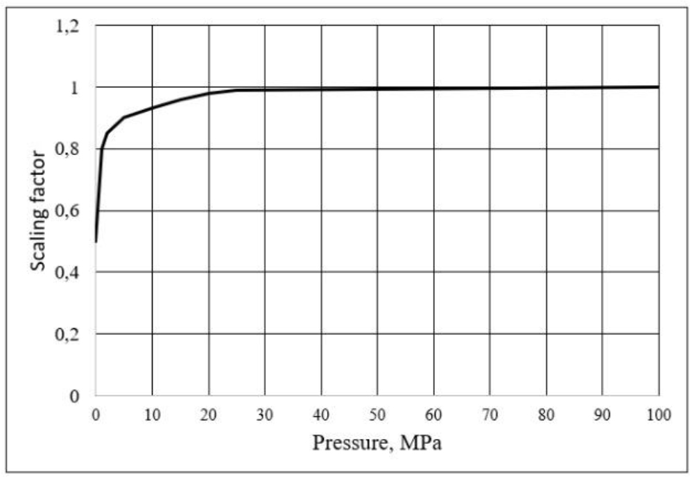
It was assumed that the maximum value of the heat transfer coefficient from the blank to the tools would be 3.5 mW/mm2K. This is the value for a tool pressure of 100 MPa. For lower pressures, the heat transfer coefficient decreases. In such cases, the value corrected by the scaling factor (Fig.7) determined by the supplier of the stamping sheet is adopted for the calculations.
Fig. 7.
Distribution of cooling channels a) in the upper part of the tool b) in the lower part of the tool
The simulation of tool heating and cooling is performed in an iterative manner. The convergence criterion of the computational process is the state at which the differences in tool temperature in subsequent iterations are no greater than 2°C. In the case under discussion, four complete cycles were required, with the Quick Numerical Cycling option enabled. This method enables a notable reduction in the number of cycles required to stabilise the temperature of the drawpiece and the tool. Instead of starting the analysis with the ambient temperature for the tools, the tool initial temperature is estimated for the first cycle, enhancing the overall efficiency of the analysis.
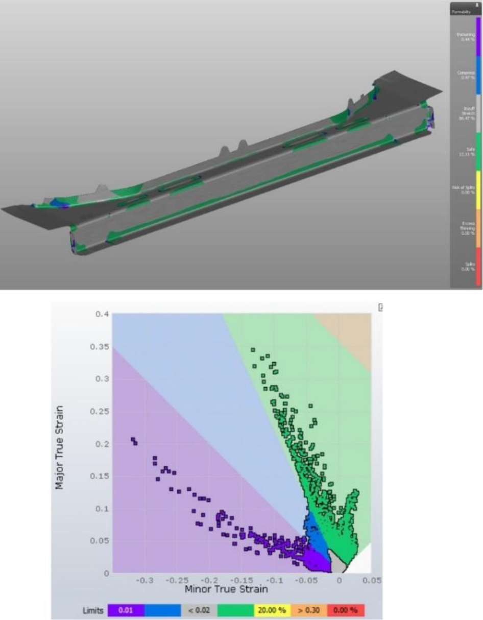
The calculations provided a number of results describing the course of the stamping process. Primarily, the FLD (Forming Limit Diagram) was subjected to analysis. The results shown in Fig.8 do not indicate any product feasibility issues. No regions susceptible to cracking were noticed.
Fig. 8.
Distribution of cooling channels a) in the upper part of the tool b) in the lower part of the tool
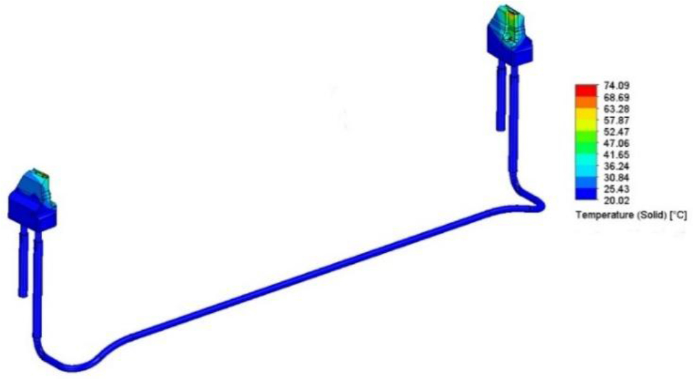
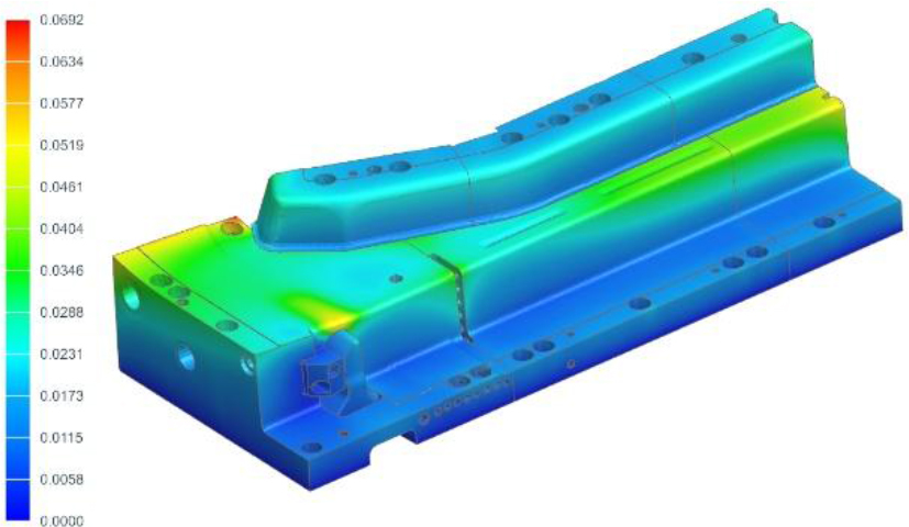
The next figure (Fig.9) shows the temperature distribution of the drawpiece at the end of the quenching process. It can be seen that the maximum temperature does not exceed 248°C and is lower than the required temperature. It is also worth noting that over almost the entire surface of the finished drawpiece, these temperatures are only slightly higher than 180°C. The two places with significantly higher drawpiece temperatures are where the lifting devices are to be located in the tool. Their function is to lift the drawpiece after the quenching process to a position where it can be picked up by the robot arm. Inside the die tools, during the quenching process, the top surfaces of the lifting devices are positioned approximately 0.5mm below the surface of the die and are therefore not involved in the intense heat exchange between the die and the drawpiece.
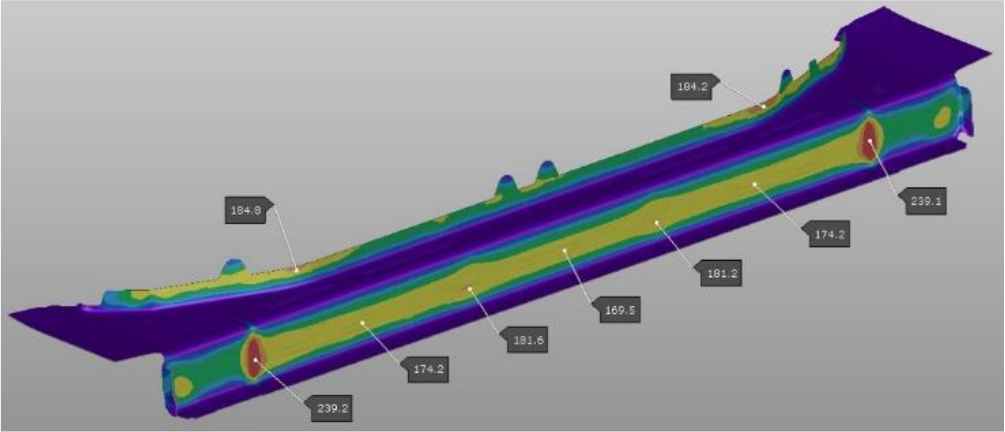
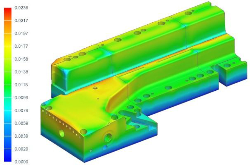
Fig.10 shows the temperature distribution on the working surfaces of the tools. As can be seen, the highest temperatures only slightly exceed 100°C, which means that the process will be able to run continuously, without the need for additional time to allow the tools to cool down.
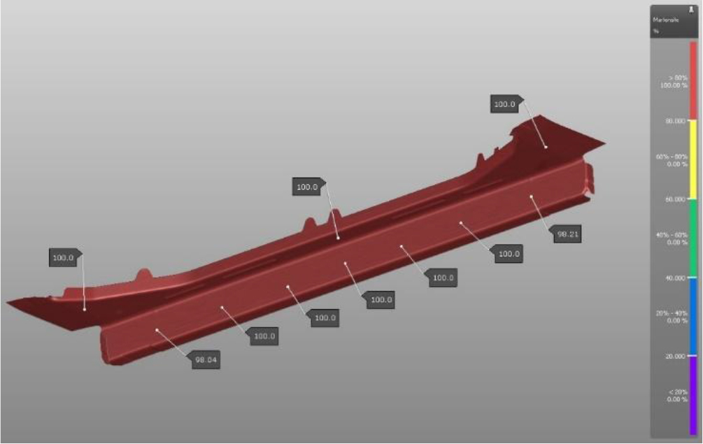
The predicted martensite distribution in the drawpiece (Fig.11) guarantees a product with the required material properties.
Based on the results of the simulations, a 3D model of the tool was made. It is a two-cavity die, the main components of which are a lower plate (ribbed cast iron) with a die, lower binder and a system of punches working in a direction other than the main stamping direction (Fig.12a), and an upper plate (ribbed cast iron) with an upper binder and forming punches (Fig.12b).
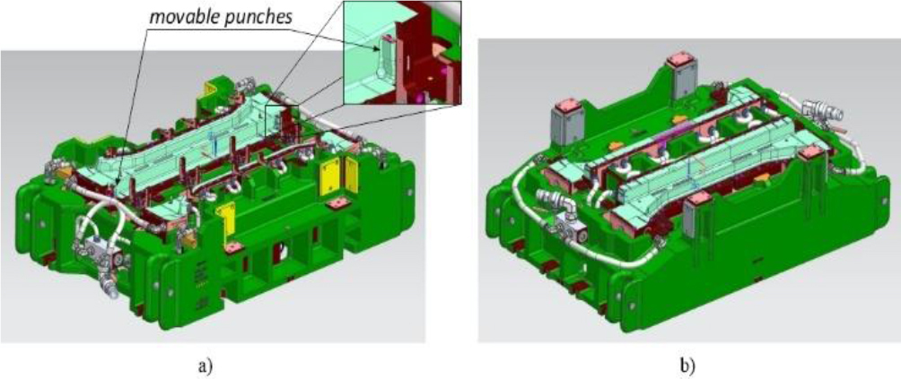
Two punch units are built into the tool, for forming flanges in a direction other than the stamping direction (Fig.13).
. COOLING SIMULATION OF MOVABLE PUNCHES
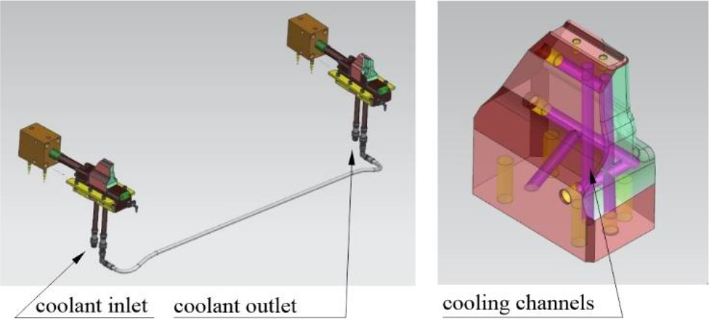
A special cooling system with drilled channels (Fig.14) was designed for the moving punch system, as for the other parts of the tool, with a separate coolant supply system.
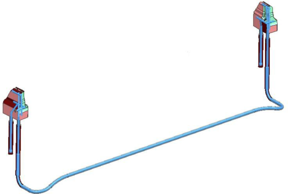
As mentioned above, when analysing the stamping process in the AutoForm package, it is not possible to simulate cooling of the tools operating in a direction other than the stamping direction. For this reason, the cooling system for the moving punches was analysed in the FloEFD thermal-fluid calculation system. Fig.15 shows a model of the system with the computational domain of the cooling fluid highlighted.
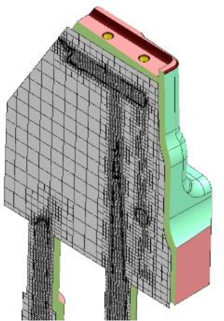
The geometric model thus prepared was discretised. The dimensions of the mesh in the discrete model were selected in an iterative manner. In successive iterations, the size of the finite elements was reduced and the effect on the results obtained (temperatures and velocities) was examined. If the results did not change significantly (more than 2%) in the next iteration, it was assumed that the finite element dimensions from the previous iteration were optimal. Fig. 16 shows, in an example section, a mesh discretising the volume of the punch and coolant adopted for the calculations. The computational model of the die consisted of 1427330 cells, of which 468882 elements represented the coolant volume.
No simulation of the stamping process is performed during the heat-flow analysis. It is therefore necessary to determine the heat flux density that the drawpiece gives off to the top and bottom of the tool during the forming and quenching processes. Then, the temperature of the drawpiece decreases from the initial temperature of t2=810°C (before the forming process), to the final temperature of t1=180°C (after the quenching process). Knowing the forming and quenching time T=14 s, the mass of the drawpiece m=4 kg, and the specific heat of the steel c=0.46 kJ/(kg°K), it is possible to calculate the heat flux
For the beam described, the flux is
To evaluate the effectiveness of the proposed cooling system, the temperature of the working surfaces of the tools was tested. Fig.18 shows the temperature distribution on the working surface of the moving punches. As can be seen, the temperatures are around 74°C, which is slightly lower than the 80°C initially assumed. It can therefore be concluded that the cooling system for the moving punches was correctly designed.
. PROBLEM OF PRODUCT JAMMING. ANALYSIS OF THERMAL SHRINKAGE OF THE DRAWPIECE AND TOOLS
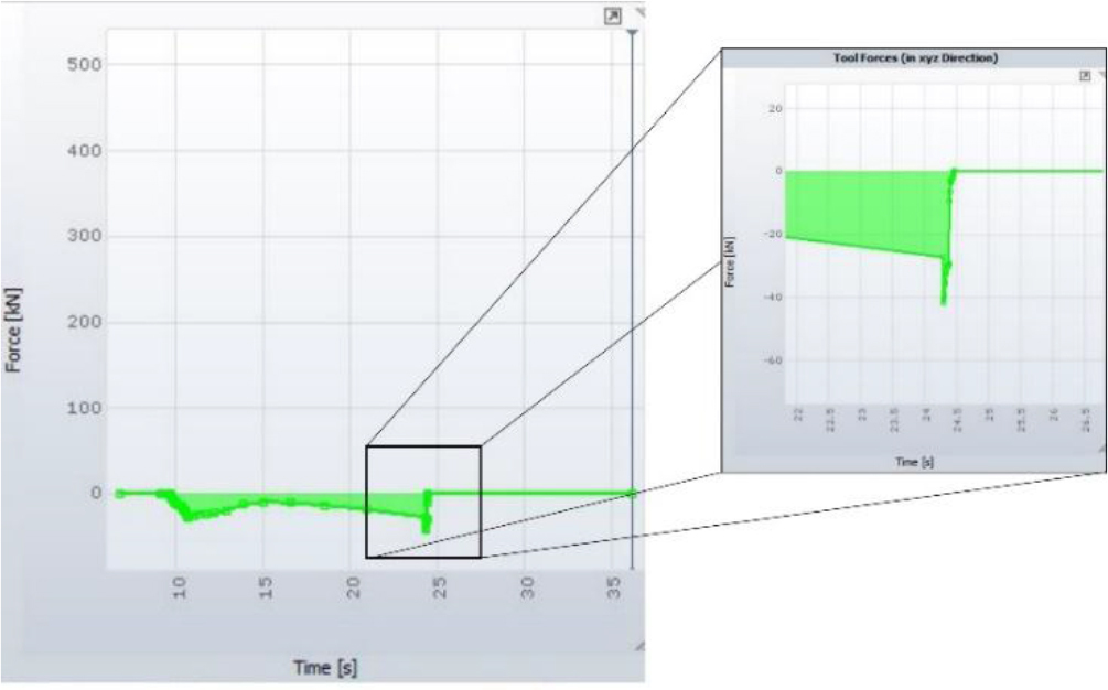
The problem associated with large-size drawpieces jamming in the tool after quenching is relatively common. Shrinkage and quenching stresses can cause problems when removing the drawpiece from the die tools. The value of the force exerted by the drawpiece on the die after cooling to the final process temperature is significant and exceeds 40 kN (Fig.19).
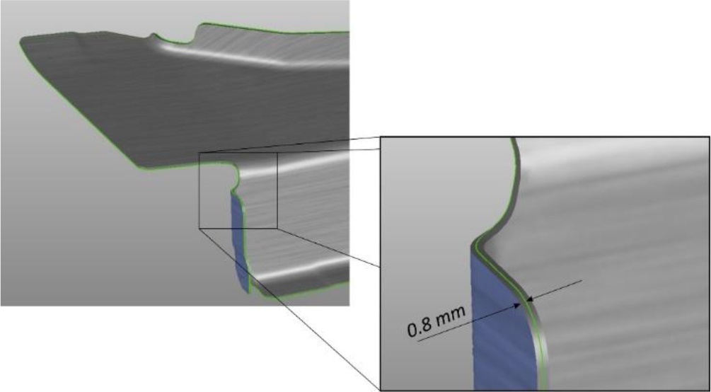
In the example described, jamming is eliminated in two ways. Firstly, based on the simulation results (Fig.20), a tool is made with a dimension that compensates for the shrinkage of the drawpieces. It is worth noting that the magnitude of this shrinkage along the beam is approximately 0.8 mm, which is half the thickness of the drawpiece. During the beam production, stamping conditions change and, within the limits agreed with the supplier, the material changes. This can result in the tool being insufficiently adjusted and the die continuing to jam. This phenomenon is going to be eliminated by the use of movable punches (retracted after hardening).
Thermal expansion of dies and punches can also be the cause of a drawpiece jamming and problems with correct tool operation. For this reason, a thermo-mechanical analysis was carried out for the lower and upper part of the tool and their deformations were determined. Simplified 3D models of the tools were developed for this analysis. These simplifications consisted in removing from the model all parts whose influence on the load and strength of the die is negligible. For reasons of symmetry, half of the top and half of the bottom of the tool were calculated (Fig.21). The models prepared this way were analysed using the finite element method in the Simcenter package.
Fig. 21.
FEM model for calculating the expansion of a) the lower part of the tools b) the upper part of the tools
The upper part of the die and lower part of the die were loaded with a heat flux
Fig. 22.
Boundary conditions for the analysis of (a) the lower part of the tool (b) the upper part of the tool
The problem was completed in two stages. First, the thermal analysis problem was solved and the temperature distribution in the tool was determined. This was followed by a static analysis under the temperature load obtained from the previous analysis. As a result of the calculations, deformation values were determined for the lower and upper parts of the tool (Fig.23 and 24) due to their thermal expansion. These values do not exceed 0.07 mm for the lower part of the tool and a maximum of 0.024 mm for the upper part of the tool. These deformations are very small and do not affect the stamping process, in particular the jamming and the dimensional accuracy of the drawpieces. It is worth mentioning that the minimum value of the clearance between the moving parts of the stamping tool (dies, punches and binders) is assumed to be 0.4 mm, i.e. many times greater than the deformation values determined.
. TESTING OF MANUFACTURED PARTS
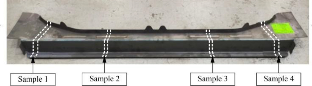
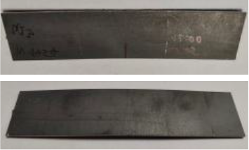
In accordance with the described project, a stamping die was made (Fig.25) and mounted on an experimental stamping line. In order to assess the correct performance of the stamping die, a test batch of 150 drawpieces was prepared (Fig.26). Mechanical parameters were then measured using both non-destructive and destructive testing methods. Non-destructive testing was carried out on 20 randomly selected drawpieces and 5 drawpieces were chosen for destructive testing.
. Non-destructive testing - measurement of mechanical properties of the drawpiece
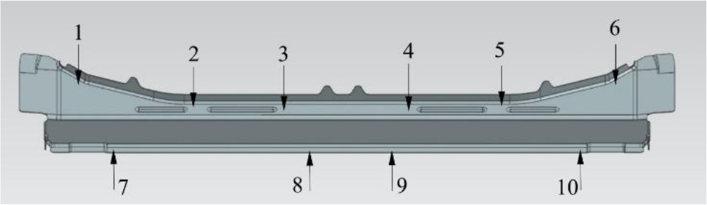
The 3MA (Micromagnetic Multiparameter Microstructure and Stress Analysis) instrument from the Fraunhofer Institute [14] was used to measure basic mechanical parameters of the drawpiece, such as yield strength Rm and hardness in Vickers degrees. Measurements were taken at 10 control points as shown in Fig. 27.
Analysing the obtained results (Tab. 1, Tab. 2), it can be concluded that for each of the drawpieces, the required mechanical parameters were achieved at each measurement point. Hardness exceeded the required value of 400 HV and the strength limit was within the expected range of 1400÷1900 MPa.
Tab. 1.
Results of strength limit measurements Rm, MPa
Tab. 2.
Results of HV hardness measurements
. Destructive testing
. Tensile test
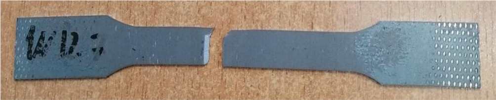
Paddle samples with a gauge length of 50 mm were cut from the flat areas of the test drawpieces using a plasma cutter. These samples were then elongated on WDW-300S testing machine from TEST Lab. During the test, the yield point and ultimate strength were determined. Fig.28 shows a photograph of a selected sample after the test, and Fig.29 shows the results of the measurements.
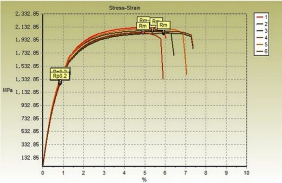
The report of these measurements (Tab. 3) confirms the production of drawpieces with the required mechanical parameters.
. Vickers hardness measurement and microstructure analysis
Vickers hardness tests and microstructure analysis after the hardening process require special preparation. Samples for microstructure analysis were cut from selected areas on the drawpiece using a water-abrasive cutter (Fig.30).
Next, the prepared material was positioned with a metallographic pin and then embedded in phenolic resin. In the next step, the samples were ground with diamond discs and polished using diamond suspensions with grain sizes of 9 μm and 3 μm and oxide suspensions with grain sizes of 0.05 μm (Fig.31).
Examples of Vickers hardness results are shown in Tab. 4. As can be seen, the obtained values for the tested samples exceed the 400HV value which is considered to be required.
Tab. 4.
Results of HV hardness measurements
| Measurement number | Imprint/value | |
|---|---|---|
| 1 | 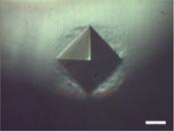 | 579.1 |
| 2 | 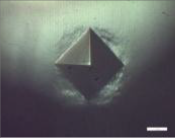 | 538.7 |
| 3 | 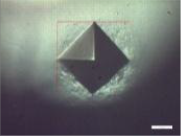 | 533.4 |
| 4 | 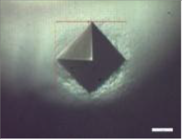 | 561.9 |
| 5 | 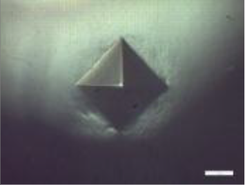 | 573.3 |
| 6 | 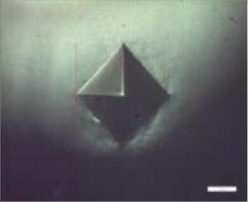 | 583.6 |
In the subsequent phase of the experiment, the samples that had been previously prepared were etched in a solution of 4% Nital-4 acid. The structure was then examined at 50x magnification using a microscope of the AmScope ME1200TC-5M Inverted Trinocular Metallurgical Microscope + 5MP Camera type. Fig.32 shows an example of a photograph taken using this microscope.
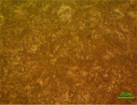
The resulting structure is a martensitic structure, which is a required outcome of the hot stamping process. It is distinguished by high mechanical properties and was observed in all samples obtained from each of the measurement areas.
. Hydrogen embrittlement test
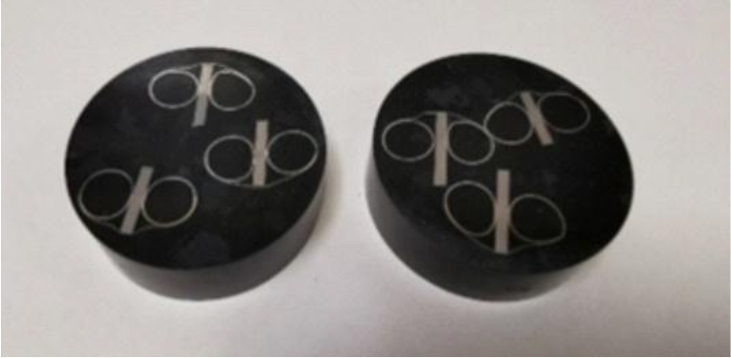
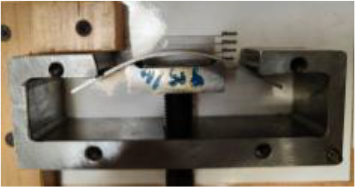
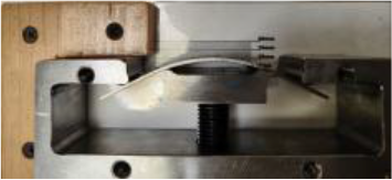
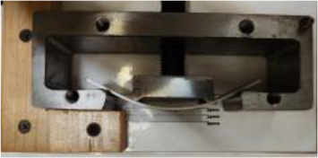
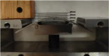
Hydrogen embrittlement occurring during the hot stamping process can lead to uncontrolled cracking of body drawpieces during normal automotive operation. A simple workshop test of a material resistance to hydrogen embrittlement is four-point bending of samples taken from the drawpiece. Such a sample, rectangular with the dimensions of 110 x 25, is placed in a special tool [14]. The punch of the tool is tightened with a screw so that the deflection of the sample induces a stress equal to 80% of the tensile strength limit. The sample is left in the tool for 300 hours and next visual inspection is performed. Table 5 presents the photographs of the tests performed. None of the tested samples showed cracks or scratches on the surface, which could mean the onset of cracking. Therefore, it can be concluded that the samples passed the four-point bending test.

. Measuring the shape-dimensional accuracy of a drawpiece
To check the shape-dimensional accuracy of the manufactured drawpieces, we first analysed the requirements defined in the technical documentation. For the drawpiece in question, the shape and dimensional accuracy was to be within ±0.5mm at the adjacent surfaces and ±1.2mm in other areas. Based on this analysis, a measurement plan was drawn up and five parts were randomly selected and measured on the CMM (Coordinate Measuring Machine). Fig.33 shows an example of the measurement report.
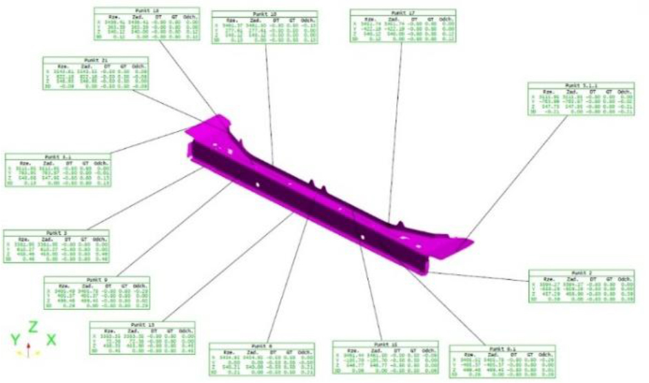
It was found that at none of the measurement points, the assumed tolerances of the drawpiece production were exceeded, particularly on the adjacent surfaces significant for the assembly of the drawpieces.
SUMMARY
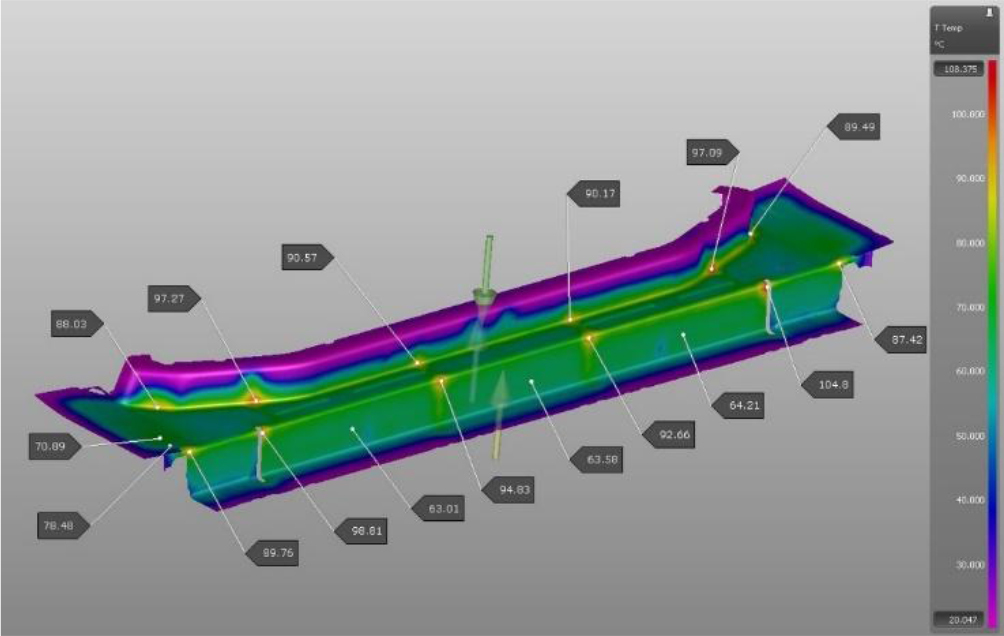
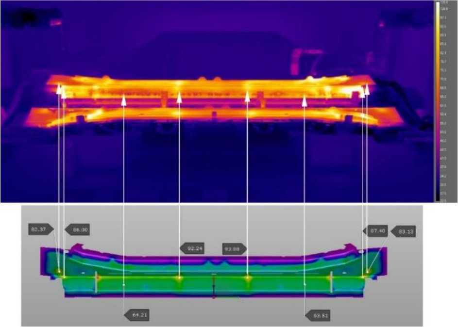
The design of a hot stamping tool with an innovative arrangement of punches operating in a direction other than the stamping direction was performed in several stages. Computer simulations constituted a significant part of the overall process. Their results include a lot of information concerning stamping and quenching processes. These include the FLD diagram, the temperature distribution on the drawpiece surface and the working surfaces of the tools, as well as the predicted distribution of martensite in the drawpiece. The evaluation confirmed that there were no risks associated with the feasibility of the detail or its quality following the stamping process. The martensitic structure guarantees the strength limit Rm=1400÷1900 MPa for the whole product and Vickers hardness of HV>400. The maximum temperature of the drawpiece does not exceed 248°C, which is lower than the required value of 250°C. The temperature distributions on the working surfaces of the tools at the end of the stamping process slightly exceed 100°C, which has a beneficial effect on the duration of the whole process. The image from the thermal imaging camera monitoring the stamping process (Fig.34) confirms the results obtained during the simulation. The obtained temperature distribution and values are similar.
Based on the results of the simulations of the stamping process, the force exerted by the drawpiece on the die after cooling to the final process temperature (approximately 40 kN) was determined. This elevated force value can be attributed to the shrinkage along the beam of 0.8 mm, which is half the thickness of the sheet. The problem of drawpiece jamming was successfully eliminated through the implementation of an appropriate correction of the working surfaces of the tool, using the controlled moving punches (withdrawn after the hardening process) and the strategic selection of tool kinematics. Furthermore, the thermal expansion of dies and punches was determined through the solution of thermomechanical analysis problems with the NX Simcenter package. This investigation concluded that the potential risks associated with the incorrect adoption of tool clearances were not present.
In conclusion, it should be stated that the possibilities offered by modern packages supporting the work of the designer of hot stamping dies, significantly shorten the time of preparation of the test series of drawpieces, and in turn have a positive impact on the financial aspect of the preparation of production processes.
Measurements of the finished drawpieces from the test series showed that all required parameters were met. Thus:
– the drawpiece material has a strength limit Rm in the range of 1400÷1900 MPa,
– the hardness of the drawpiece after hardening is greater than the required 400 HV,
– the material of the drawpiece after hardening has a martensitic structure,
– the drawpieces passed the hydrogen embrittlement test,
– the beams produced have the required shape-dimensional accuracy.