
INTRODUCTION
Poland is one of the world’s leading producers of the common mushroom (Agaricus bisporus) [1], [2]. In 2021, Poland accounted for 32% of global exports of fresh mushrooms, corresponding to a volume of 232,000 tons, with an estimated value of 397.3 million EUR. Major European importers included countries such as the United Kingdom, Germany, and France. Polish mushrooms are competitive due to their low cost and high quality, which is attributed to manual harvesting practices [1]. Rising production costs, driven by increased energy prices and minimum wage hikes, create favourable conditions for exploring the automation of harvesting processes. Producers may be interested in reducing labour demands while maintaining the high quality of the product.
During visits to local mushroom farms, it was determined that mushrooms are cultivated on tiered shelving units within specialized production halls. These halls are equipped with systems to regulate optimal temperature, humidity, and carbon dioxide levels. Depending on the room’s construction and dimensions, the shelves can reach up to 2 meters in depth, 4 meters in height, and over 30 meters in length (with the length typically limited only by the hall’s size). Each production hall contains several shelving units arranged in rows. Harvesting is done manually, with access to higher shelves facilitated by mobile ladders mounted on the racks.
Currently, there are few automated harvesting systems available on the market. However, in recent years, there has been a noticeable increase in the number of patents related to components of mushroom-harvesting robots or complete harvesting systems, with the majority of patents filed in China which is the world's largest producer of mushrooms overall (not limited to Agaricus bisporus). Existing solutions include systems based on Cartesian robots [3], moving along shelfs [4], [5], [6], SCARA-type robots [7], [8], [9], and specialized harvesting combines. These systems differ in their approach to picking mushrooms: some selectively harvest based on specific criteria, such as cap diameter, while others cut all mushrooms growing on a given shelf. Most systems require either dedicated shelving with guiding rails for the robot or significant modifications to the shelving structure. For producers, this means additional costs related to altering existing infrastructure and extended production downtime due to the installation of the new system.
The goal of the authors of this publication was to design and develop a prototype of a SCARA-type robot system for the automated harvesting of Agaricus bisporus mushrooms, with minimal modifications required to existing infrastructure. This design can be also used for other applications e.g. for sweet peppers, apples, tomatoes [10], [11], [12], [13], [14], also as, a part of heavy equipment [15], [16]. This paper is not focused on techniques of picking and processing mushrooms widely described in [8], [17], [18], [19], [20], This system is primarily intended for further research, testing, and development, so particular emphasis has been placed on modularity and scalability. Naturally, the platform presents potential for adaptation to other harvesting applications in agriculture. With minimal modifications, it could be tailored for the harvesting of straw-berries, pears, apples, peppers, and tomatoes. A review of literature in this field highlights a growing global trend toward such solutions [21], [22].
In 2019, an article was published [5] describing the design and operating principles of a robot based on a Cartesian coordinate system, intended for the selective harvesting of mushrooms. The robot's structure was divided into specific zones: a Visual area, a Picking area, and an auxiliary area. A similar solution was proposed and patented by the company MYCONOCS. Industrial mushroom harvesting can also be conducted by a harvester manufactured by Vandentop Mushroom Equipment BV, which is designed to harvest Agaricus bisporus mushrooms by cutting them from the substrate. The operation of this machine, like previously discussed solutions, involves the harvester moving along the shelf on support tracks that serve as guiding rails. A significant difference is that the BQ Harvesting machine is not designed for selective harvesting, meaning that the harvested mushrooms require additional sorting or are entirely designated for processing. The literature also includes numerous studies on the mechanics of mushroom extraction and the design of gripping systems.
MUSHROOM CULTIVATION
The cultivation of Agaricus bisporus can be conducted in various ways, but certain aspects remain consistent across different systems. Button mushrooms are grown on an organic substrate so called compost produced from fermented straw, horse, pig, or chicken manure, and additives (e.g., gypsum) [23]. Production can be divided into three stages: First phase involves compost fermentation, which often takes place at a separate facility from the main cultivation site. Initially, the compost ingredients are shredded, softened, and then mixed in specific proportions. This begins the compost fermentation process, during which bacterial activity rapidly increases the compost’s temperature to around 80°C as bacteria convert carbohydrates and proteins into ammonia and heat. For high quality compost, the process must be continuously monitored, with adequate oxygen supplied throughout. Traditionally, compost turning, such as with pitchforks, was used to achieve this, but in industrial scale production, specialized halls or tunnels with aerated floors are employed. After this stage, if needed, the compost is transported to the main production facility. In second phase, the compost undergoes pasteurization, typically by using steam to heat it to a temperature between 56°C and 60°C, where it is maintained for 6 to 10 hours. This process eliminates flies, their eggs and larvae, mold spores, and any other unwanted organisms. The temperature is then lowered to around 45°C, and fermentation continues for an additional 4 to 5 days. At this point, Agaricus bisporus mycelium is introduced into the compost. Third phase is known as full colonization of the compost by the mycelium, which develops over the next 16-18 days at an ambient temperature of 25°C. The compost is covered with a casing layer that adjusts the pH to approximately 7.8 and encourages the mycelium to transition from its vegetative state to its reproductive stage. At this stage, maintaining strict hygiene and cleanliness within the production hall is crucial, as the crop requires large volumes of air. The halls are heavily ventilated, and any infection present could spread rapidly through the airflow, potentially affecting the entire crop within the hall. Agaricus bisporus cultivation also requires a high relative humidity level of up to 90%, temperatures ranging from 18°C to 25°C, an elevated level of carbon dioxide, and adequate oxygen levels. This necessitates continuous monitoring of the hall’s climate conditions, the use of specialized climate control equipment, and frequent watering of the compost. Button mushrooms (Agaricus bisporus) are typically harvested in two or three waves. The third harvest, however, constitutes only about 10% of the total yield and carries a higher risk of infection in the mushrooms, so it is sometimes skipped. The yield generally ranges from 35 to 40 kg of mushrooms per square meter of cultivation area [23].
Construction of shelves for mushroom cultivation
The design of shelving units used for mushroom cultivation is not standardized. However, most commercially available solutions share similar characteristics (Fig. 1). Manufacturers offer versions made from aluminium, galvanized steel, or a combination of these materials. Due to the corrosive conditions within production halls, steel components are hot dip galvanized for adequate durability. Powder-coated or wet-painted elements are not used, nor are stainless steel components, due to the high production costs associated with the latter.
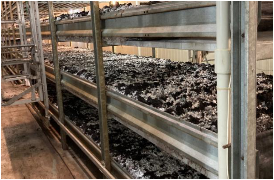
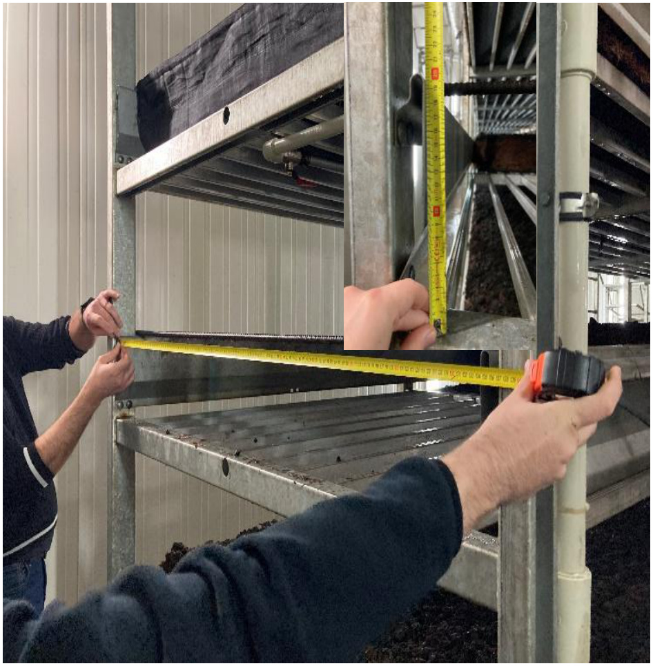
To best replicate working conditions and develop project assumptions, a visit was made to a local mushroom producer. The building used for cultivation is divided into smaller rooms with cultivation shelves. Each room has its own climate control system, managing parameters such as ambient temperature, compost temperature, humidity, and carbon dioxide concentration. The doors to each room have a special design that ensures a tight seal, facilitating the control of these parameters and reducing the risk of infection spread. Dividing the cultivation space into separate rooms allows for rotation through various growth phases, improving efficiency and reducing costs. While the first hall is being cleaned and prepared for laying compost with mycelium, mushrooms in the second hall are growing, and harvesting is taking place in the third. The work began with a visit to the mushroom farm and measurements of the shelves for growing this mushroom Fig. 2. Measurements are summarized in Tab. 1.
DESIGN OF ROBOTIC ARM
The initial requirements analysis enabled the development of a layout concept: the target system must be equipped with a horizontal moving axis for coarse positioning along the shelf, a vertical Z-axis that allows the robot to move between shelf levels and simultaneously pull out mushrooms, and a two-link arm functioning like in SCARA-type robots. This arm must achieve the precision necessary to position itself over the mushroom and pick it up using a gripper.
The SCARA configuration (Selective Compliance Assembly Robot Arm) is most commonly used for performing fast and precise assembly operations or pick-and-place applications [24], [25]. The selective compliance typically occurs in the X-Y plane, allowing components to be inserted into sockets and holes, while maintaining rigidity along the Z-axis. SCARA robots are known for some of the highest movement speeds among all kinematic configurations, due to the limited number of axes (e.g., compared to six-axis manipulators), which also simplifies inverse kinematics calculations and reduces the load on the controller. This configuration is also recognized for its excellent positioning accuracy and repeatability.
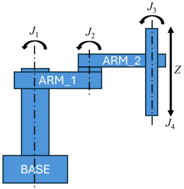
The structure of the SCARA manipulator is shown in Fig. 3. It is important to note that axes J1, J2, and Z are parallel to each other, unlike in the spherical RRP manipulator, where they are perpendicular. Additionally, industrial applications commonly feature configurations where axis J3 is aligned with axis Z, enabling simultaneous rotational and linear motion of the end effector. One unusual variant of this configuration includes robots with an inverted joint sequence: the robot arm with two rotational axes is mounted on a long vertical linear axis. This design provides a very high working space while maintaining high speed, accuracy, and repeatability, along with a compact arm size. Such robots are typically used for loading and unloading parts from shelves and racks - the absence of a protruding screw at the end of the arm, which usually forms the Z-axis, allows the arm to be inserted into low spaces between shelves.
Main requirements for robotic arm
The analysis of the work environment carried out on the basis of literature data and a site visit to the production plant allowed us to determine the exact requirements that should be met by the robot included in the automatic system for harvesting two spore mushrooms and to formulate design assumptions:
The robot is to enable selective harvesting of mushrooms, selecting mushrooms only from a specific range of cap diameters, with the possibility of setting this range.
PRR structure - Moving the prismatic element to the beginning of the kinematic chain and suspending the robot's arms from it saved space. This allowed us to achieve a flat arm structure. Both the flat substrate used for growing mushrooms and the mushrooms themselves are characterized by unevenness. Another reason for this approach is the range of image capture by the camera mounted on the end of the arm. The higher above the crop, the larger the area covered.
The robot's executive part must fit in the space between the shelves, without interfering with the structure of the rack. The height of this space was set at 250 mm measured from the highest point of the mushroom cap to the lower surface of the next shelf.
The arm's reach must be at least 1000 mm. This parameter does not provide full coverage over the shelf, which is 1340 mm, but the designers assumed that the robot would be able to work on both sides, then 100% of the crop coverage is achieved. The second important issue is avoiding the vertical sloping edges of the shelf structure. The longer the arm, the more difficult this becomes. Finally, the mass of the robot's joints affects the dynamics of movement and the required torque.
The robot must be able to move along the cultivation rack so that the entire length of the rack fits within the robot's work zone.
The robot must be able to harvest mushrooms on all shelves of the rack or additional equipment must be designed to enable this. Due to the limitations of the room in which the robot prototype will be tested, the height of the highest shelf was assumed to be 2000 mm above the floor level.
The robot must be characterized by a maximum modular structure, allowing easy and quick redesign to adapt to the conditions on the production floor of a potential customer.
It was assumed that one growing rack can be serviced by more than one robot to ensure that the entire growing rack can be serviced or to increase efficiency.
The minimum harvest efficiency was set at 10 s/mushroom.
Positioning accuracy ±1 mm in all directions.
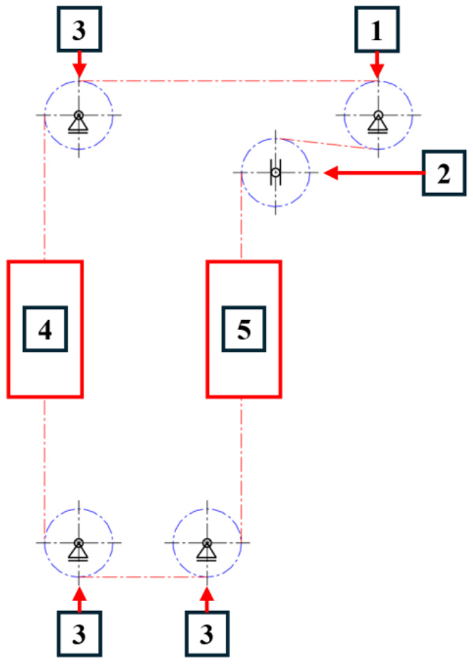
The kinematic structure of the robot is shown in Fig. 4. In this case, the PRR configuration is more advisable due to the limited space between shelves and the possibility of changing the working position between subsequent levels of mushroom cultivation. It uses an autonomous mobile platform (1) to move along the growing rack. Thanks to this, the platform gains the ability to move along the racks. Due to the large maximum height of the rack and the lack of upper rails, it is necessary to create a support structure (2) for the long axis Z, used for rough movement of the arm (3) between shelves. The support structure must be sufficiently massive and stable to transfer the forces resulting from the acceleration of the arm, especially when it is at its maximum height. The concept assumes the use of a platform on rails with its own drive to move along the cultivation rack (1).
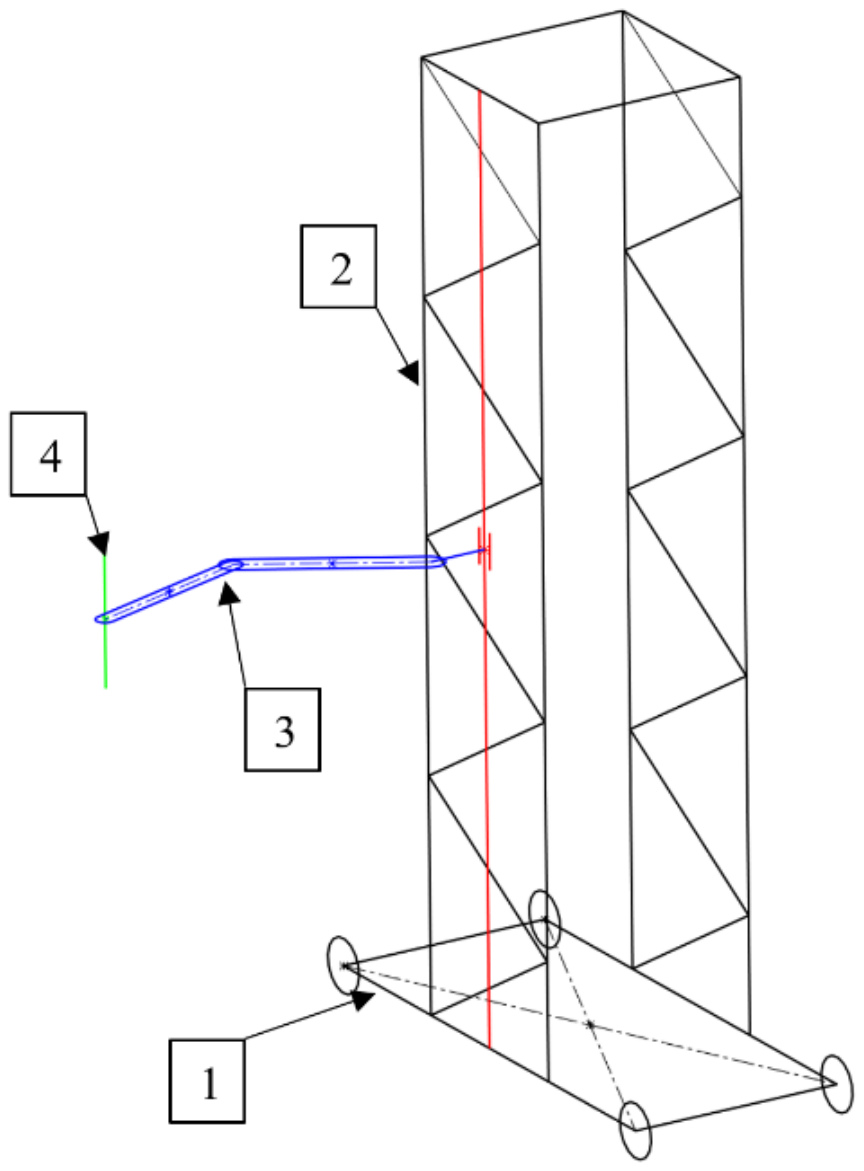
Fig. 4. Sketch of the concept of a mobile SCARA robot (PRR configuration), moving on an autonomous mobile platform on the floor of a cultivation hall; 1 – mobile platform; 2 – support structure; 3 – SCARA arms; 4 – end effector e.g flexible gripper or suction cup
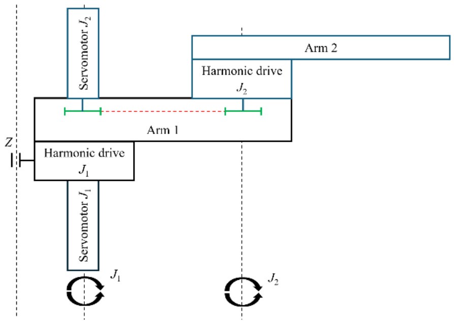
To drive the Z axis, it was decided to use a drive unit consisting of a servo motor, planetary gear, toothed pulleys and a toothed belt. The kinematic diagram of the system is shown in Fig. 5, in side view. As part of the prototype design, it was assumed that the range of movement in this axis should be at least 1700 mm. As the supporting structure of the Z axis, it was decided to use an extruded aluminium profile, which is characterized by high manufacturing accuracy, especially straightness, allowing for the mounting of linear guides without the need for machining.
Kinematics of robotic arm
The detailed diagram of the arm structure is shown in Fig. 6. The location of both servo motors in the J1 axis allowed for minimizing the moment of inertia of the entire arm and minimizing the load on the J1 servo motor. The harmonic gears were used not only for precise multiplication of the engine torque, but also as a bearing for the arm in both axes of rotation (cross roller bearings). This solution simplifies the design and reduces the weight. The harmonic gears are also characterized by a very low value of the backlash between the teeth and a compact design and low weight, especially in comparison to other types of guides with the same ratio [26]. The torque is transmitted from the J2 servo motor, attached to the J1 member, to the J2 gear using a toothed belt. This is associated with the risk of introducing additional backlash in the drive system, created at the contact between the toothed belt and the pulley, but placing the harmonic gear behind the toothed belt effectively reduces these backlashes by the transmission ratio. The J1 and J2 members, in terms of design, must be characterized by low weight, which is to improve the dynamics of the system, and high stiffness so as not to undergo deformations that could negatively affect the operation and accuracy of positioning. Due to the prototype and individual nature of the designed system, the option of manufacturing the arms using aluminium alloy casting technology was rejected from the outset. Three basic manufacturing technologies were therefore considered: milling the arm monoliths from aluminium blank, a welded structure made of aluminium and then machined, and a structure screwed from aluminium plates. During arrangements with subcontractors, and due to the possibility of gaining additional experience and specialist knowledge, it was decided to use welding technology and machining. In turn, initial estimates suggested that cutting the monolith would be the most expensive option, and the version screwed from plates could be characterized by insufficient stiffness in relation to the mass.
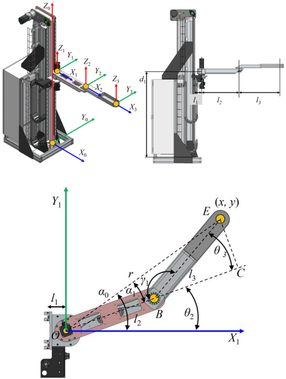
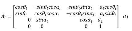
The presented robot has three degrees of freedom: one vertical prismatic and two rotational in a PRR configuration. The J1 and J2 axes move in the X-Y plane, and the joints are rotatable around the vertical Z axis. The robot's kinematics are presented in Fig. 7. To determine the position of the mushroom picking effector (suction cup or flexible gripper), the equations of forward kinematics were determined. The position is derived using the classical Denavit-Hartemberg (DH) convention. The parameters are summarized in Tab. 2.
Tab. 2.
DH parameters
| Axis i | Twist angles αi-1 | Link length a i-1 | Link offset di | Joint angles θi |
|---|---|---|---|---|
| 1 | 0 | l1 | d1 | 0 |
| 2 | 0 | l2 | 0 | θ2 |
| 3 | 0 | l3 | 0 | θ3 |
By substituting the data from Tab. 2 into matrix (1), three matrices were obtained:
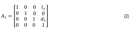
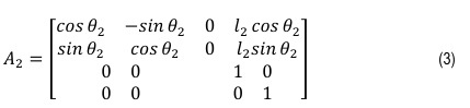
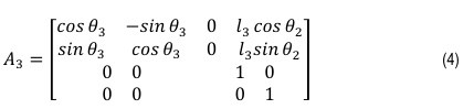
The end effector position was determined by multiplying the determined matrices:
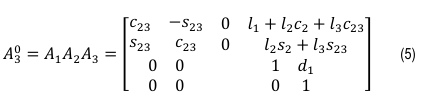
Therefore, the position of the effector can be written as follows:



To determine the inverse kinematics equations, consider the case of a planar two joint arm. By designating points O as the centre of the coordinate system and joint J1, E as the working end of the arm, and B as joint J2, we can determine the length r by connecting points OE and write the formula:

using the law of cosines r can be written as:

using trigonometric reduction formulas, the formula obtains the form:

by performing mathematical operations in this way, one of the angles was determined:

From the Fig. 7, angle θ2 can be written as:

and

The missing angle α1 can be written as a tangent function in a triangle with vertices OCE:


By substituting the values of (14) and (16) into the formula (13), the value of the θ2 was obtained:

Arm design
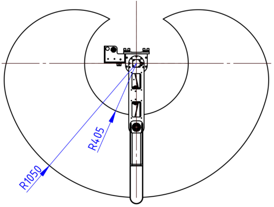
Fig. 8 shows a three dimensional model of the arm attached to the Z-axis carriage. Arm consists two subassemblies, lower arm and upper arm. A strain wave gear, designated DSC-25-50-PO (2), is bolted directly to the carriage (1). It also acts as a torque multiplier generated by the J1 axis servo, designated EM1-C-M-40-2-B-F-0-D (3), and connects the supporting structure of the J1 link (4) in relation to the carriage, using a milled body (5) bolted to the output sleeve of the gear. The second servo motor, driving the J2 axis: EM1-C-M-40-2-B-F-0-A (6), is attached directly to the upper surface of the J1 link. Both the upper and lower surfaces of the J1 link have service inspections, sealed with covers (7) made of laser cut galvanized sheet metal. At the end of the J1 member, a harmonic gear (8) is mounted, which simultaneously supports the J2 member (9). The J2 member structure is finished with a mechanical interface (10) allowing for the assembly of a mushroom picking gripper module. A hole is provided in the side wall of the J1 member to allow for tensioning the belt (11). Fig. 9 shows in detail the transmission of the drive from the J2 servo motor to the J2 harmonic gear unit. In order to improve the clarity of the drawing, the system is shown from below, and some parts are hidden. A toothed belt pulley (2) is attached to the output shaft of the J2 servo motor (1) using a special adapter sleeve (3) and a KTR-105-14-26 clamping and expansion sleeve. The drive is transmitted to the output belt pulley (5) using the AT5 toothed belt (4), and then to the J2 harmonic gear unit (6) designated DSG-25-50-AH. In the middle of the system there is a tensioner unit consisting of two smooth wheels (8) guiding, a tensioning gear (7), a tensioner body (9) and a tensioning screw (10). By routing the belt in the shape of the Greek letter Ω, it is possible to tension the belt with the required force while simultaneously shortening the path covered by the tensioning wheel. The presented arm structure allows for obtaining the envelope visualized in Fig. 10.
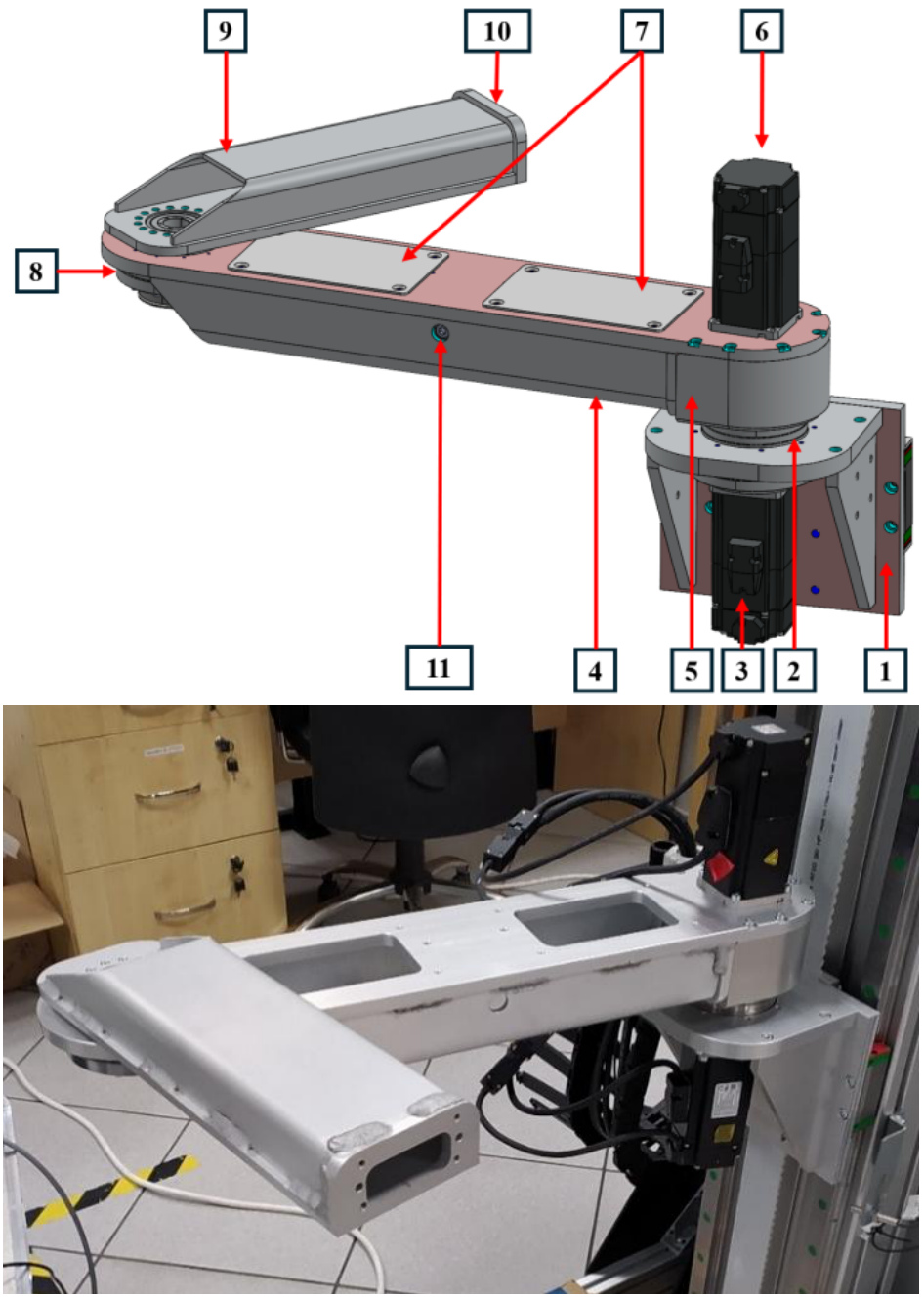
Fig. 8. CAD model and assembled arm where: 1 – carriage; 2 – strain wave gear; 3 – servomotor; 4 – linkage; 5 – gear adapter; 6 – servomotor; 7 – covers; 8 – strain wave gear; 9 – arm; 10 – mechanical adapter face plate
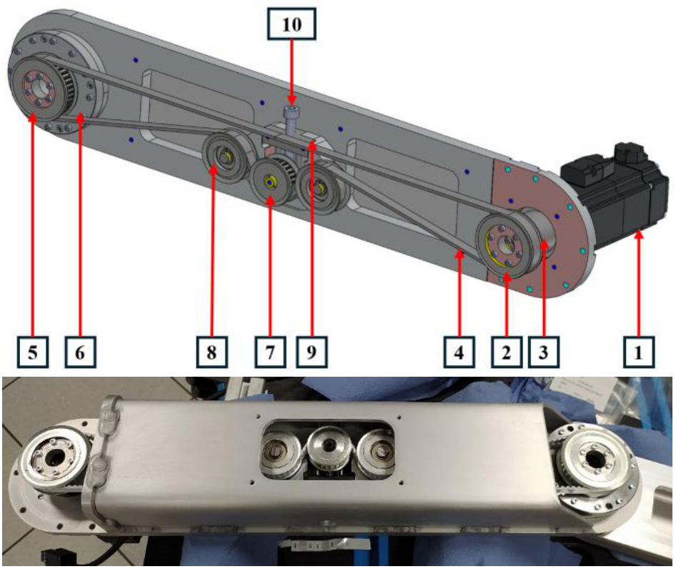
Z axis design
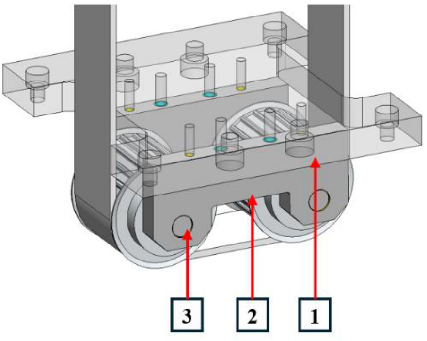
To create the Z axis supporting structure, an extruded aluminium profile from ITEM series 10 with cross-section dimensions of 200x100, manufacturer's number 0.0.624.68, length 1840 mm was used. Two HIWIN linear guides with the manufacturer's number CGR25R and length 1750 mm were screwed to the profile, thus creating a travel track for the arm carriage. The upper (Fig. 11) and lower (Fig. 12) profile ends are fitted with housings for fastening the toothed belt pulleys.
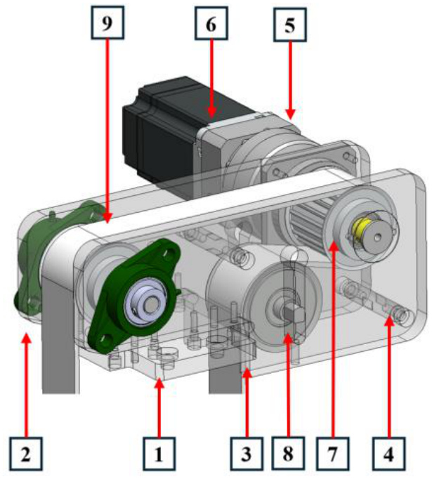
Fig. 11. CAD model of upper part of Z axis with drive where: 1 – base plate; 2, 3 – side plate (semi-transparent); 4 – reinforcement rood; 5 – planetary gear i=10; 6 – servomotor; 7 – timing pulley; 8 – smooth wheel, 9 – timing belt
The upper housing, in addition to guiding the belt, also serves as a mounting for the servo drive with a gear and as a belt tensioner. The housing structure consists of three plates: a base plate (1), fastened to the profile, and two side plates: left (2) and right (3). The side plates are additionally reinforced by connecting them with cylindrical rods (4). A planetary gear WVRB-090-010-K-P2, i = 10 ratio (5) working with the servo drive (6) and driving the wheel (7) is fastened to the left plate. The smooth pulley (8) moved along the cutouts in the side plates is responsible for belt tensioning. The lower body is used to guide the belt and attach the column to the frame, its construction is also based on three plates: the base (1) and two identical side plates (2). Between the side plates, mounted on axles (3), there are two pulleys with internal bearings. To convert the rotary motion to linear motion, a toothed belt with open ends was selected (9). It is attached to the Z-axis carriage by two clamping plates. The Z-axis carriage itself is made of bolted aluminium plates to minimize weight. The carriage movement is supported by two HIWIN carriages marked CGL25CAZ0C, cooperating with the previously described guides.
Motor sizing
In order to determine the torque, first of all, the equivalent moment of inertia must be determined for each servo motor. In all cases, the procedure is the same. It is the sum of the moments of inertia in the kinematic chain, and the basis for determining it is the kinetic energy of the entire system. First, the kinetic energy for the Z axis was determined. The equations for the remaining drives were written in a similar manner to this methodology. Based on Fig. 5 motor sizing can be done. Mass of moving arm mr is approximately 22,27 kg (summarized in Tab. 3), counterweight mcw is 12 kg and timing belt mb1 1,3 kg.
Tab. 4.
Simplified BOM of robotic arm from Fig. 8
The equivalent inertia of system can be described as:

where Er is reduced kinetic energy (KE), Ei is kinetic energy of i-th element in drive system.
For Z axis equation can be described as follows:

Where ESMZ is KE of Z axis servomotor rotor, EPGB is KE of planetary gearbox, EP is KE of pulley, EARM is KE of whole arm assembly, ECW is KE of counterweight and ETB is KE of timing belt.
Knowing that the angular velocities before and after the planetary gear are different, they can be described as follows:

where ωZ2 is angular velocity in output of gearbox, ωZ1 is angular velocity in input of gearbox (=servomotor rotor), i is gear ratio.
Therefore the linear speed of the Z axis is:

where rp1 is pulley pitch radius.
By further substituting into the equation, the following notation was obtained:

where I are moments of inertia of aforementioned components, m are mases.
After substituting into the formulas and arranging the equation, it can be written that the equivalent inertia is:

Motor No. 3 (Fig. 7) moves the entire arm A1 (arm 1 + arm 2 Fig. 6), assuming the angle between the arms is 180 degrees. For motor No. 6 (Fig. 7), which drives arm 2 (A2) calculating the reduced moment of inertia requires taking into account the drive train between the output shaft and the gearbox.
Equivalent inertia for J1 (Fig. 6) motor is:

Equivalent inertia for J2 (Fig. 6) motor is:

A table of moving masses and mass moments of inertia was also prepared for the calculations (Tab. 4.). These values were obtained from catalogues or the Solidworks graphics program used to create the project. It was verified that the indicated masses and moments of inertia corresponded to the actual values.
Tab. 4.
Moments of inertia used for torque calculations
When calculating the driving torque for the Z-axis movement, the influence of gravity acceleration on the mass motion must also be taken into account. The torque resulting from the load TL can be described by the following equation:

where mL is load mass, that can be described as mr - mcw for the arm to move upwards, at this point more torque is needed, which is due to the inequality of the counterweight and arm masses, g is gravitational constant, Dp1 is pulley pitch diameter, α is inclination angle, µ is frictional coefficient, η is efficiency.
The Z axis performs two main types of movement: during mushroom picking, it lowers at a low speed until a mushroom is captured, and then slowly pulls it out. The second type of movement involves moving between shelves at high accelerations and speeds. The forces acting on the system during mushroom picking are relatively small compared to the loads resulting from the high accelerations of the entire system, so the components were selected for the latter case. The highest load on the servo motor will occur during the upward acceleration of the carriage – inertia loads must be added to the loads resulting from the system's action. The following parameters (Tab. 5) were taken into account in the torque calculations. This is significantly less compared to market robots. However, it's important to note the different kinematics, in which the Z axis speed cannot compete with the same movement in the RRPR configuration due to its mass.
Tab. 5.
Moments of inertia used for torque calculations
| Z axis | J1 | J2 | |
|---|---|---|---|
| Joint speed | 1,1 m/s | 205 deg/s | 350 deg/s |
| Servo motor acceleration | 3141,51 rad/s2 | 1486,74 rad/s2 | 2052,94 rad/s2 |
| Acceleration time | 0,12 s | 0,12 s | 0,15 s |
| Calculated torque | 2,13 Nm | 1 Nm | 0,86 Nm |
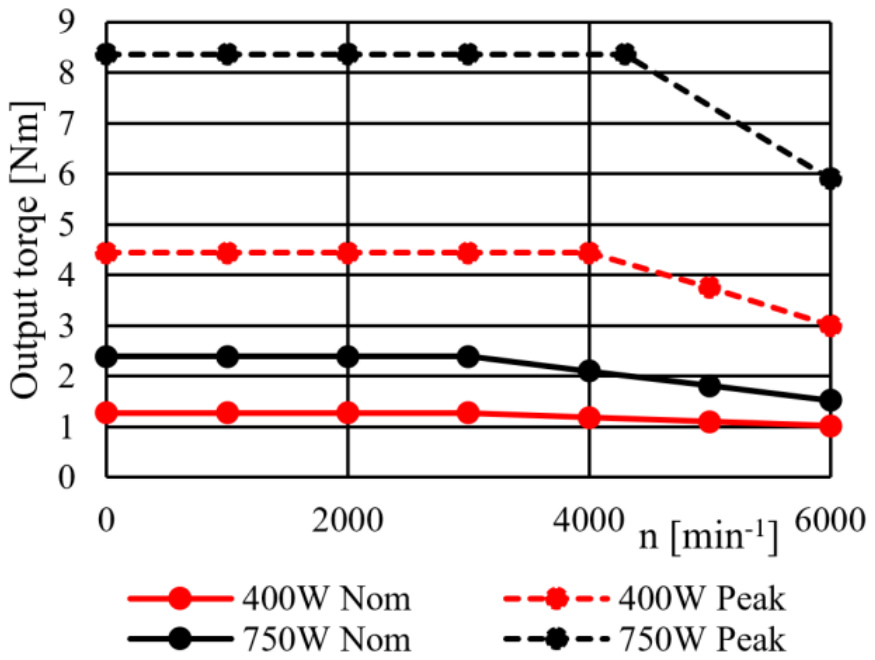
The calculations resulted in motors with power of 750 and 400 W, whose parameters are summarized in Tab. 6. The torque vs. speed characteristics are shown in Fig. 13.
Tab. 6.
Servo motors parameters
Control system
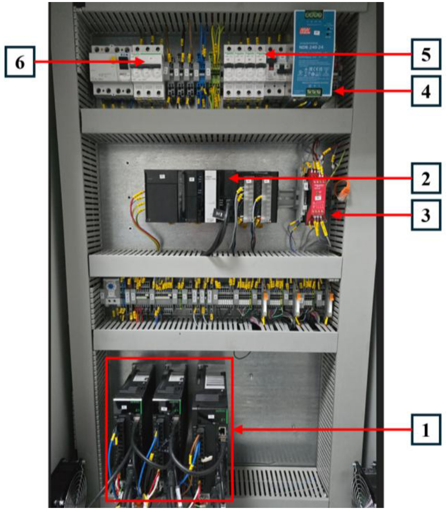
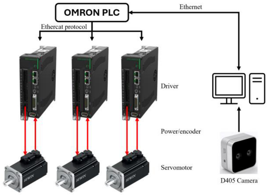
The robot's control system was implemented using an Omron 1000 PLC. The entire control system is housed in an electrical cabinet integrated with the robot's supporting structure (Fig. 14). The controller processes data from the vision system, which returns the coordinates of mushrooms ready for harvesting. This results in the angles in the arm's joints and the Z-axis position. A harvesting attempt is then performed. After the harvest is complete, the robot arm is positioned in a new programmed position. This process is repeated until all mushrooms in the designated area have been harvested. Dedicated drivers are used to power the servo drives; they support emergency stops and brakes, and have an internal feedback loop based on readings from a 23-bit incremental encoder. Compared to industrial robots equipped with absolute encoders, it was necessary to implement a homing function. This function is required in the event of a power outage or an emergency stop signal. The structure of the control system is shown in Fig. 15.
DESIGN AND EXPERIMENTAL SETUP DESCRIPTION
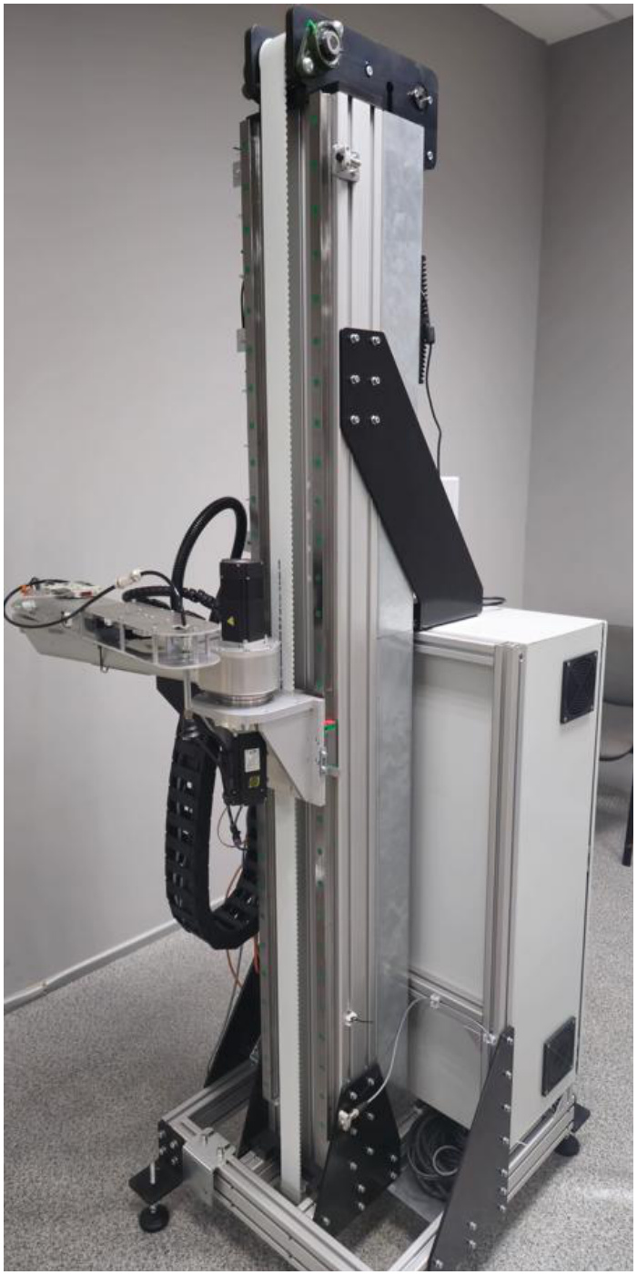
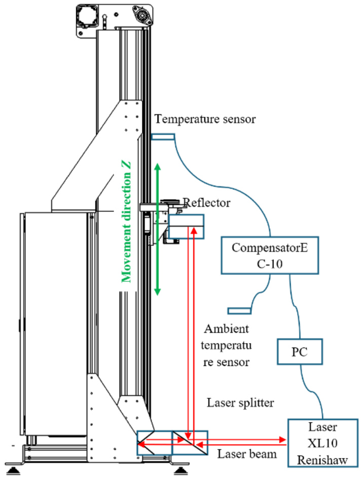
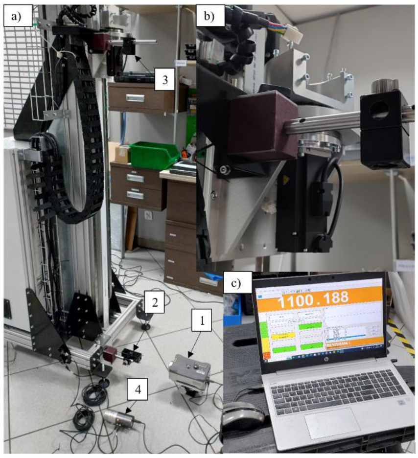
The result of the design work is the platform presented in Fig. 16. The aim of the authors of the work was to check how the moving mass of the arm affects the accuracy and repeatability of positioning along the Z axis. Therefore, it was decided to carry out the tests based on the PN-ISO 230-2 standard, which specifies the procedure for measuring the accuracy and repeatability of the positioning of a single axis of numerically controlled machine tools. The measurements were performed using a system based on a Renishaw laser interferometer. A detailed diagram of the measurement system is shown in Fig. 17, and the actual, assembled system is shown in Fig. 18.
The research system consisted of:
the tested object, i.e. the Z axis of the robot,
the XL-10 laser, generating a laser beam with a wavelength of 633 nm, and equipped with a phase shift detection system for the returning light,
a laser beam splitter and a fixed reflector, reflecting the reference beam,
a moving reflector, attached to the Z axis carriage, reflecting the measurement beam,
the EC-10 compensation unit, whose task is to introduce corrections to the measurements based on the ambient temperature and the body temperature,
an ambient temperature sensor,
a body temperature sensor,
a computer with Renishaw software, collecting and analyzing the data.
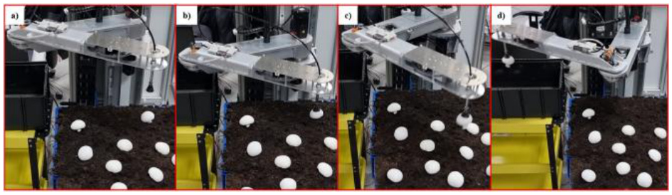
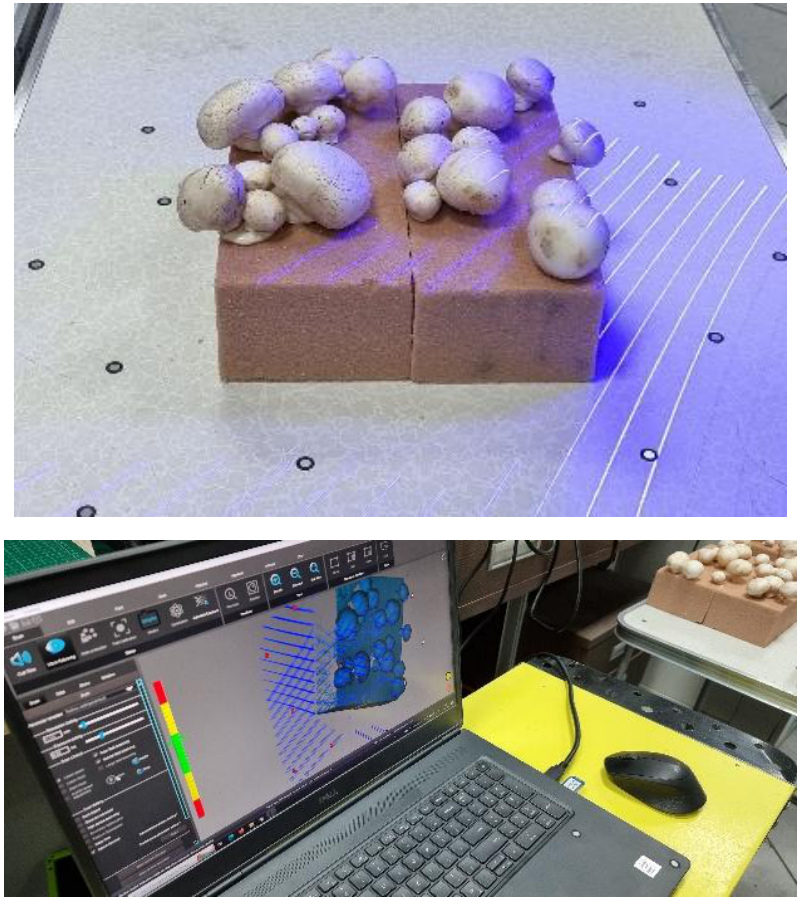
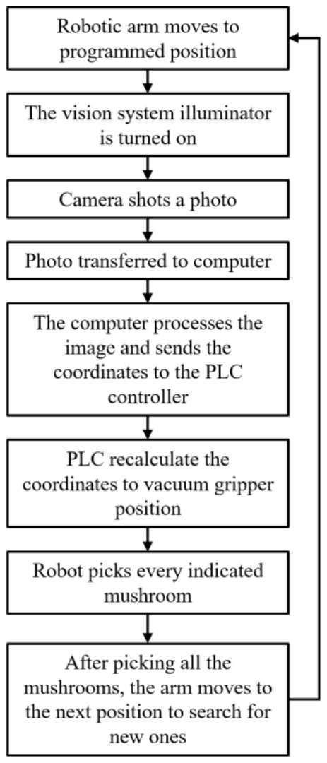
The Fig. 19 shows a typical designed robot work cycle. These studies were conducted in laboratory conditions. Due to the delicate nature of the mushrooms, they were 3D scanned, and then the processed models were printed using FDM technology using white filament (Fig. 20). This allowed for simulation of the robot's operation and the developed software. Process starts by scanning and detection of a mushroom by the vision system together with recognition of the cap diameter and height in the Z axis. Based on the reverse kinematics equations implemented in the PLC controller, the arm is positioned above the object. The Z axis moves to catch the object, pick it up, and then put it back to the indicated place.
RESULTS
The positioning accuracy and repeatability tests according to ISO 230-2 consist in performing a series of measurements in which the tested axis (in the discussed case the Z axis carriage) takes a given position and maintains it until the actual position is measured and recorded. It is required that (for axes up to 2000 mm long), the measurement is performed at least at five points per meter of the axis length – i.e. at most every 200 mm. The measurements must be performed in accordance with the standard test cycle. Each position must be reached five times in each approach direction.
After calibration of the measuring system, consisting in precise setting of the parallelism of the laser beam to the tested axis, the first series of measurements was started, without any software compensation of positioning errors. The measuring section of the axis was assumed to be 1400 mm, 15 measuring positions were determined at 100 mm each. 3 measuring cycles were performed in both directions of approach in accordance with Fig. 22.
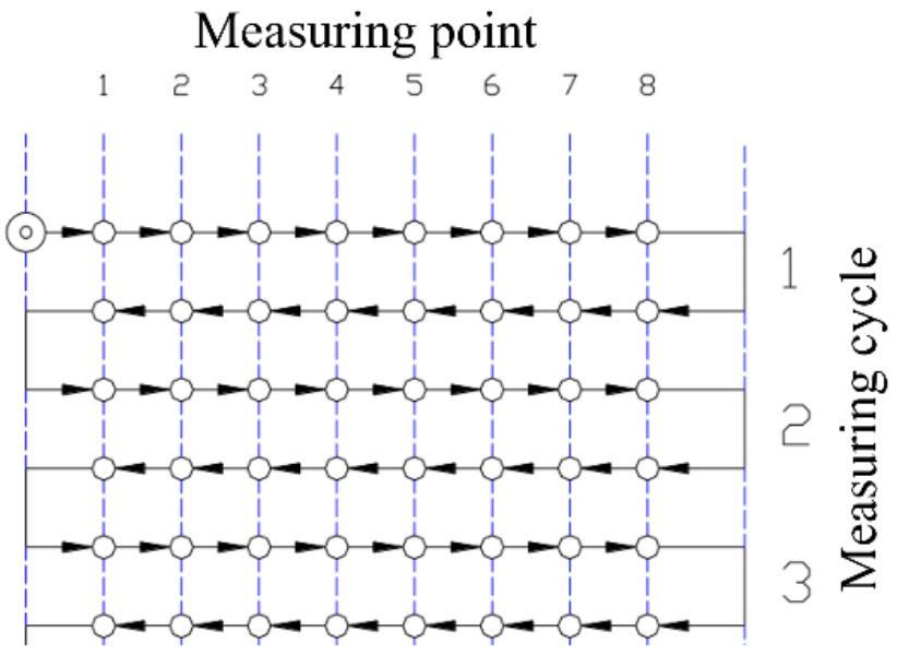
Fig. 23 shows the unprocessed data collected by the measuring system. Fig. 24 shows the data processed by the system, with the determined values of individual errors. Analysing the obtained measurement results, it should be noted that the positioning error is very high. Error is respectively Aup1=627,9 μm (↑upward direction), Adw1=676,0 μm (↓downward direction), bidirectional Abi1=958,9 μm. Taking into account also the very good repeatability of unidirectional positioning Rup1=53,3 μm and Rdw1=22,7 μm. System has low bidirectional positioning repeatability Rbi1=519 μm. it can be concluded that one of the reasons for the low positioning accuracy may be the backlash occurring in the drive transmission system: planetary gears, gear output shaft – pulley and pulley – toothed belt. The influence of the backlash occurring in the planetary gear is confirmed by the return error values Be1=514,7 μm and mean value -326 μm.
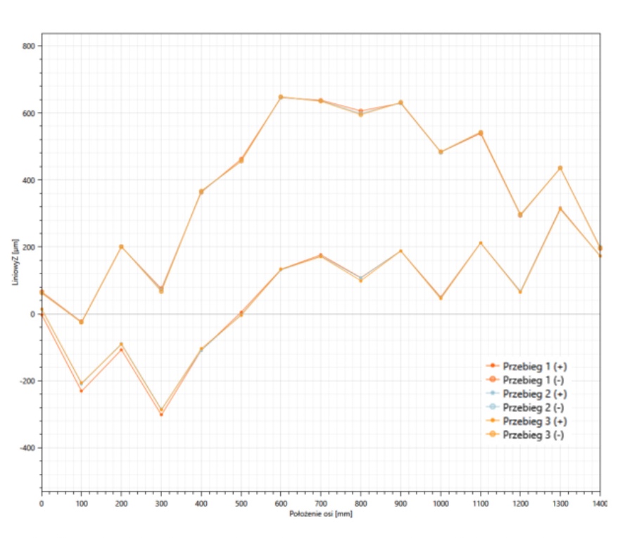
Fig. 23. Graph of deviations from the target position of the Z-axis carriage, raw data from the system, measurement series 1
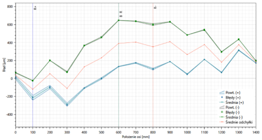
Fig. 24. Graph of deviations from the target position of the Z-axis carriage and the values of individual positioning errors, processed data, measurement series 1
To more accurately identify the potential source of positioning inaccuracy, it was decided to repeat the measurement. In the second series of measurements, a measuring section of 1430 mm was assumed, the number of measuring points was 14 and the distance between successive points was 110 mm. These values were assumed based on the circumference of the drive pulley of 220 mm - this pulley has 22 teeth and works with a 10 mm pitch AT10 belt. If the high value of the positioning error is due to problems related to the drive pulley, then the measurement series carried out in this way should show higher values of the positioning error and systematic positioning error, because the measuring points will always fall on the same points on the drive pulley.
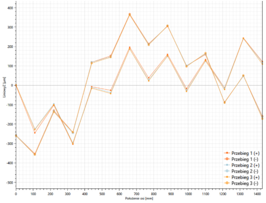
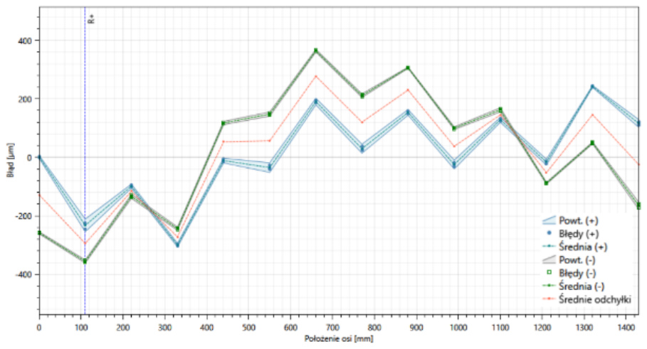
Fig. 25 shows clear data from second measuring series. Next Fig. 26 shows processed data with determined errors according to ISO 230-2.
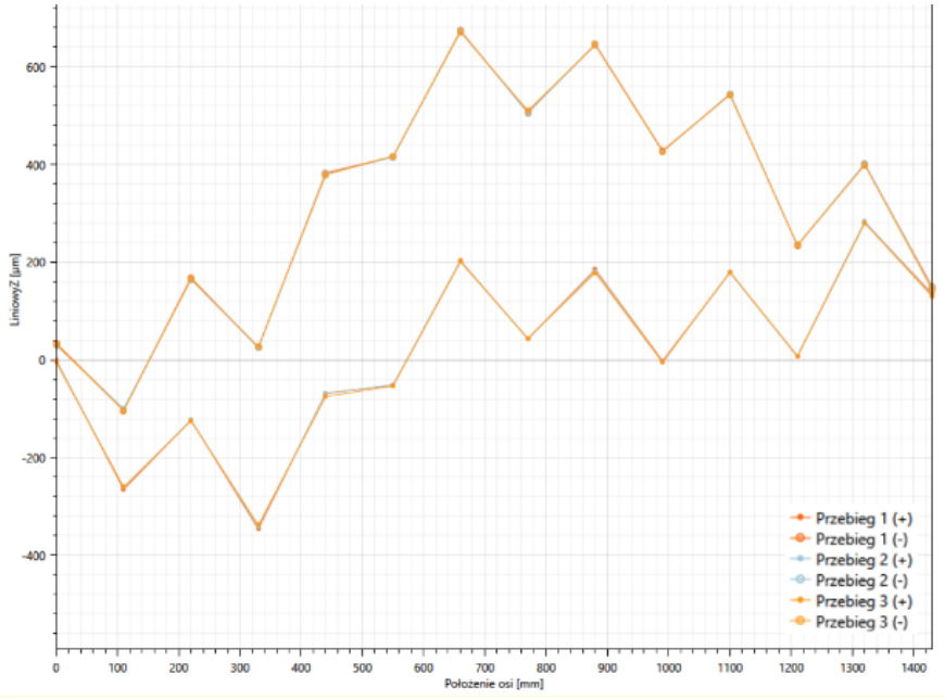
Fig. 25. Graph of deviations from the target position of the Z-axis carriage, raw data from the system, measurement series 2
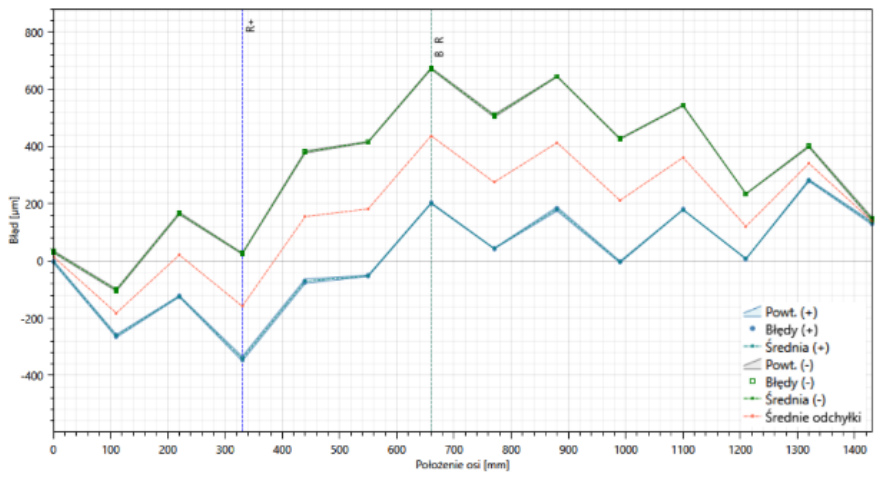
Fig. 26. Graph of deviations from the target position of the Z-axis carriage and the values of individual positioning errors, processed data, measurement series 2
As expected, an increase in the positioning error value was observed to Aup2=634.7 μm, Adw2=781.7 μm and Abi2=1025.7 μm, respectively. At the same time, an improvement in the unidirectional positioning repeatability was noted to Rup2=16.0 μm, Rdw2=12.0 μm and bidirectional positioning repeatability to Rbi2=475.7 μm, as well as a reduction in the return error Be2=470.7 μm and the mean return error to -309.0 μm. It was decided to perform an additional measurement series on a short measuring section located in the middle of the Z axis movement range. A 440 mm long section was assumed, corresponding to two full revolutions of the drive wheel, the distance between the measuring points was 10 mm. The measurement was performed in a single cycle, and the obtained data was not processed - the values of individual errors were not calculated. The raw data graph is shown in Fig. 27.
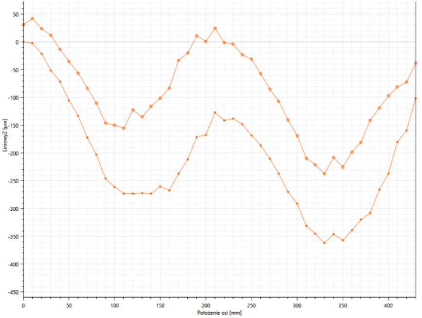
Fig. 27. Graph of deviations from the target position of the Z-axis carriage, data unprocessed by the system, measurement series 3 – examination of the influence of the drive wheel on positioning errors
The above graph shows large deviations in position even over a short section. In addition, the deviation value increases and decreases with the pulley revolutions (half a wheel revolution corresponds to a displacement of 110 mm). This suggests that one of the main factors influencing the high error value may be the radial run-out of the drive pulley. The software prepared for controlling the axis did not allow for all the corrections that are standard in machine tools, but it was possible to introduce a correction for the return error. After entering the value of this correction based on the values from Fig. 26, measurement series 4 was carried out, assuming the parameters as in series 2: 3 measurement cycles, a measuring section 1430 mm long and 14 measuring points at a distance of 110 mm each. The raw data was collected in the form of a graph in Fig. 28, and the data after processing and determining the values of individual errors in Fig. 29.
The fourth measurement series showed a significant improvement in the positioning error after the introduction of the feedback error correction. Bidirectional positioning error Abi4=730,2 μm, other errors: Aup4=551,4 μm; Adw4=730,2 μm. Reduction in the return error Be4=306.7 μm and the mean return error to -0.5 μm. Repeatability of unidirectional positioning Rup4=43,1 μm and Rdw4=24,4 μm, bidirectional positioning repeatability Rbi4=306,7 μm.
DISCUSSION
Further improvement of axis parameters can be achieved in two ways: by introducing compensations and correction factors in the program and by design changes. Software compensation is present in all CNC machines and is the cheapest solution. Modern machines even offer the possibility of introducing corrections for individual axis sections in the form of a table. However, such large deviations in positioning accuracy suggest the need for design changes and the use of higher quality mechanical components.
Despite meeting the assumptions regarding the Z-axis positioning accuracy of ±1 mm, the designed Z-axis drive system can be characterized by a much higher positioning accuracy, which can be seen from the very good repeatability. If both repeatability and accuracy were low, further improvement of the parameters would be very difficult. However, analysing the graphs obtained during the tests, it is possible to indicate mechanical areas that may potentially affect the low positioning accuracy. Fig. 27 indicates the radial run-out of the drive wheel. When designing this node, the most economical solutions were used, which may negatively affect the operation of the system. A cross-section of this node is shown in Fig. 30.
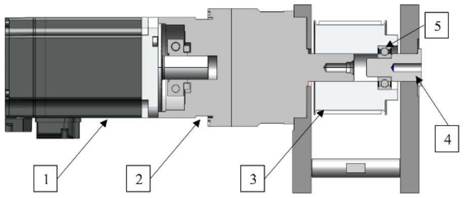
Fig. 30. Cross-section of the Z-axis drive system node. 1 – servo motor, 2 – planetary gear, 3 – drive pulley, 4 – supporting axis, 5 – ball bearing
The drive pulley is mounted directly on the output shaft of the planetary gear, and the torque is transmitted using a prismatic key. On the other side, the pulley is supported by a stationary supporting axle, with a ball bearing in between. This solution can result in the drive pulley running out, caused by the misalignment of the output shaft of the gear and the supporting axle, and the play occurring at the drive pulley - supporting axle connection. In addition, the pulley was made by machining a semi-finished product in the form of a pulley with a pilot hole, so there is a very good chance that the holes and countersinks were not made concentrically with the teeth. All the pulleys in the system were made in a similar way, and each of them can have a negative impact on the positioning accuracy.
To improve this node, the first step would be to check the quality of the pulley, which can be easily done by measuring the radial runout after mounting the pulley, e.g. in a lathe chuck. In the case of a large deviation, the pulley should be replaced, and the Z axis should be remeasured. A more expensive solution, but also more reliable, is to redesign the node. The drive pulley should be mounted on a separate shaft running through the entire upper body and connected to the planetary gear by a coupling.
Another cause may be deviations in the straightness of the profile constituting the Z axis column, and thus the rails guiding the carriage. During assembly, it was only possible to verify the mutual parallelism of the rails. However, replacing the extruded profile with a structure subjected to machining will significantly increase the costs of making the robot, and any deviations in straightness that may occur can be eliminated by using software compensation, unchangeable for a given structure. The last potential mechanical defect of the motion system is the local stretching of the toothed belt. In the author's opinion, after eliminating the above, a positioning accuracy of 0.1 mm can be expected.
In the next stages of work on the robot's motion system, it would be necessary to check the accuracy and repeatability of the J1 and J2 axes positioning, expand the project with a mobile platform for the robot to travel along the cultivation shelf, and perform tests of harvesting two-spore mushrooms. The current state of the project includes a modular and easy to adapt mechanical structure, so additional equipment should not interfere with the existing structure. After successful harvest tests, the project should be further developed with storage areas for the collected mushrooms, work should be carried out to ensure the safety of operators, and some of the nodes should be redesigned for serial production. As part of the work, a prototype robot motion system for mushroom harvesting was created that meets the geometric requirements that resulted from the analysis of the work environment. The adopted design assumptions and construction solutions proved to be effective and at the same time economical. The tasks performed as part of the work contributed to the development of the author's competences and consolidated knowledge in the field of mechanics and machine construction.
CONCLUSIONS
In summary, the set goal of building a robotic platform has been achieved. The obtained positioning accuracy will not be of major importance in agricultural and plant cultivation applications. In combination with machine vision systems, such a system will easily handle the harvesting of vegetables or fruits. Increasing the positioning accuracy will only unnecessarily increase the cost of building the device without any real impact on work efficiency.