
Introduction
Laminated composite plates are extensively employed in aerospace, marine, civil, automotive, wind-energy and defense structures because they offer an exceptional stiffness-to-weight ratio, high specific strength, corrosion resistance, and the flexibility to tailor mechanical behavior through stacking sequence design. Potential applications include lightweight aircraft and spacecraft panels, naval hulls and offshore platforms, automotive body structures, wind turbine blades, defense armor systems, pressure vessels, high-performance mechanical components such as robotic arms, industrial machinery frames, gears and shafts, and precision engineering structures where weight reduction and high strength are critical.
Owing to these advantages, composite laminates are often employed in load-bearing components where both bending and shear responses must be predicted with high fidelity. In moderately thick and thick plates, transverse shear strains contribute significantly to overall deformation. Classical Plate Theory (CPT), however, assumes that normals to the mid-surface remain straight and inextensible, thereby neglecting shear deformation. As a result, CPT yields inadequate predictions for laminated plates with low aspect ratio ratios. The First-Order Shear Deformation Theory (FSDT) [1], originally developed to incorporate transverse shear deformation, introduces linear variation of shear strains through the thickness. Although FSDT improves accuracy over CPT, it still requires empirical shear-correction factors to enforce zero shear stresses at the plate surfaces—a limitation that restricts its applicability to general laminated configurations and introduces model-dependent uncertainties. These shortcomings motivated the emergence of Higher-Order Shear Deformation Theories (HSDTs), which aim to describe realistic, smooth, and physically consistent shear-strain distributions without relying on correction factors. One of the early higher-order formulations [2] introduced a cubic variation of in-plane displacements, laying the mathematical foundation for subsequent refined shear deformation theories. Classical bending descriptions and shear-deformable formulations presented in earlier works [1–3] form the conceptual basis upon which modern generalizations were constructed. Over the years, an extensive family of HSDTs has been developed, including polynomial-based, trigonometric, exponential, sinusoidal, and generalized displacement models [4–8]. These formulations substantially enhance accuracy for both symmetric and antisymmetric laminates, particularly under complex loading and boundary conditions. Additional advancements include zig-zag theories and layer wise models [9], which capture slope discontinuities at material interfaces, thereby improving the representation of interlaminar stresses. Nonlinear kinematic models [10] expanded the predictive capability for large-deformation bending, while isogeometric extensions [11] introduced higher smoothness and geometric fidelity through spline-based approximations. Collectively, these developments have significantly broadened the ability of higher-order theories to represent the complex deformation behaviour inherent in layered composites. A major stream of research shifted from polynomial-based functions to non-polynomial shear functions, which inherently satisfy traction-free shear stress conditions at plate surfaces. This eliminated the need for artificial correction factors and produced more physically realistic shear variations. Exponential shear functions, refined trigonometric functions, and sinusoidal shear functions [12–18] demonstrated smooth, non-oscillatory distributions of transverse shear stresses while maintaining computational efficiency. Among these, cotangent-based shear functions [19] provided an elegant mathematical approach because they naturally enforce zero shear stresses at the top and bottom surfaces while delivering realistic curvature-dominated shear behaviour. Despite their promise, cotangent-based theories have been explored almost exclusively in closed-form analytical studies and, notably, have not been integrated into finite-element formulations. This absence represents a significant and unaddressed research gap, especially given the practical necessity of FE-based analysis for complex engineering structures. Parallel to theoretical advancements, finite-element (FE) implementation of higher-order theories has progressed rapidly. Several C⁰-continuous elements [20–22] were developed to overcome shear locking and to eliminate the need for C¹ continuity, making them suitable for general-purpose plate analysis. Multilayered and refined FE models [16, 22] enhanced interlaminar stress predictions, while aspect-ratio-dependent modeling recommendations [23] improved element selection for accuracy and stability. Further developments include post buckling analyses for composite plates [24], advanced models for functionally graded beams [25], and studies of plates with cutouts under various boundary constraints [26]. Inverse trigonometric shear deformation theories have also been implemented within FEM frameworks [27], demonstrating strong agreement with higher-order and three-dimensional benchmarks. Research on vibration modeling, delamination behaviour, and comprehensive surveys of HSDTs [28–30] collectively highlight the expanding scope and maturity of higher-order plate modeling. Exact elasticity solutions and refined plate models reported in literature [31–33] provide crucial benchmarks for validating newly developed theories. These solutions enable rigorous testing of shear stress accuracy, displacement convergence, and interlaminar stress behaviour metrics essential for evaluating the reliability of FE-based formulations. The present work directly addresses the gap in existing literature by introducing the first finite-element implementation of an inverse-cotangent higher-order shear deformation theory for laminated composite rectangular plates.
Recent studies have demonstrated the importance of higher-order shear deformation theories incorporating transverse stretching for accurate plate analysis. A generalized HSDT-based mixed finite element formulation developed for functionally graded sandwich plates [34] showed that transverse stretching is essential for accurate prediction of bending behavior and transverse shear stresses. Similarly, a unified HSDT-based mixed formulation was employed for laminated composite plates [35], reporting improved convergence toward elasticity solutions when thickness stretching effects are included. Furthermore, the buckling behavior of laminated composite plates was investigated using a mixed finite element approach [36], highlighting enhanced numerical stability and accuracy. Although these studies establish the effectiveness of mixed HSDT formulations, further investigation of functionally graded sandwich plates considering different boundary conditions and improved computational efficiency remains limited. The present work addresses these aspects and extends existing formulations to provide an accurate and efficient framework for the analysis of FG sandwich plates.
The proposed nICSDT formulation capitalizes on the inherent advantages of inverse-cotangent shear functions, ensuring exact satisfaction of traction-free shear boundary conditions without requiring shear correction factors. Closed-form laminate stiffness matrices are derived through symbolic thickness integration, significantly improving numerical stability and computational efficiency in the FE implementation.
The formulation is developed using a MATLAB-based higher-order FEM framework and is validated against benchmark problems for simply supported laminates subjected to sinusoidal (SDL) and uniformly distributed loads (UDL). The results demonstrate excellent agreement with three-dimensional elasticity solutions, particularly in predicting transverse shear stresses, through-thickness distributions, and global bending response.
The Mathematical Formulation
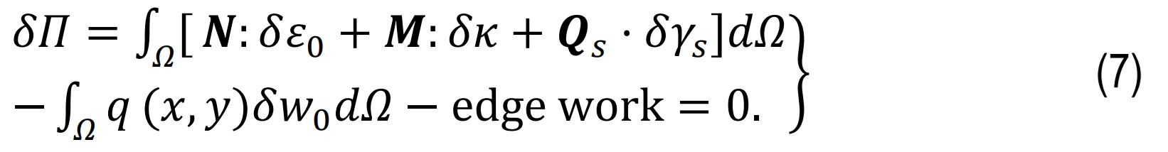
The mathematical formulation for laminated composite rectangular plates defines the kinematics, material properties, and governing equations for bending and deformation under various loads. An inverse-cotangent higher-order shear deformation function is employed to capture realistic transverse shear effects without shear correction factors, and the governing equations are derived using Hamilton’s principle for finite element analysis.
Geometry and Laminate Description
Consider a laminated rectangular plate as shown in Fig.1 occupying the mid-surface domain(x,y)∈[0,a]×[0,b] with total thickness h and coordinatez∈[-h/2]×[+h/2].The laminate is composed of N perfectly bonded, homogeneous orthotropic plies. Each ply k has thickness hk , fiber orientation Qk , and reduced constitutive matrix Q(k) .
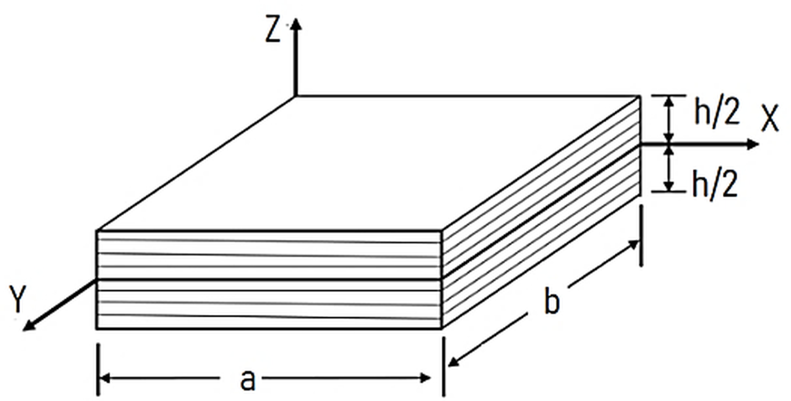
The mid-surface of the plate is defined at z=0, with coordinates(x,y,0). A transverse mechanical load q(x,y) acts on the top surface of the plate.
Displacement Field and state of strains
The present new Inverse-cotangent HSDT (nICSDT) is formulated based on the displacement fields shown in Eq.1. The displacement field explicitly enforces zero transverse shear traction at top/bottom surfaces [27].
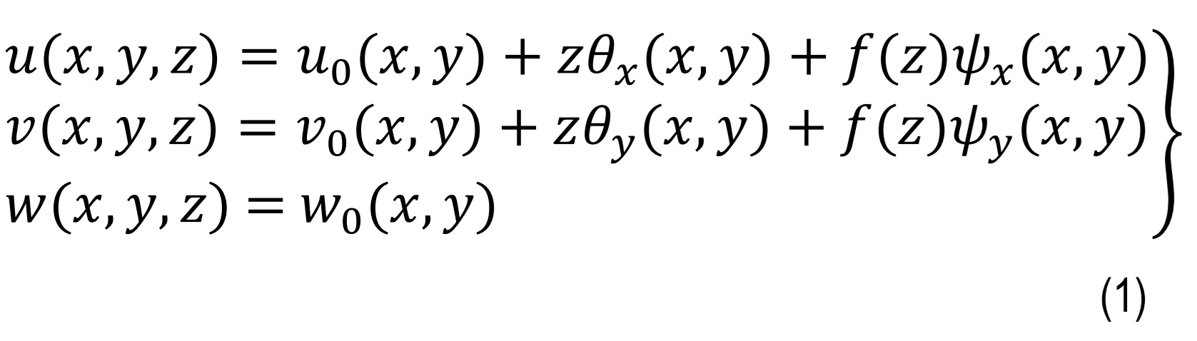
where,u0(x,y), v0(x,y), w0(x,y) are mid-surface displacements and θx,θy,ψx,ψybeing rotations of the transverse normal while higher order shear functions, f(z) is an inverse-cotangent shear function of the form f(z)= cot-1(h)/(z)-(16)/(15)(z)/(h)3. This function provides smooth shear variation through the thickness and automatically satisfies τxz=τyz=0 at z=-h/2 so removes shear correction factor requirement while enhances accuracy for moderately thick laminates. The state of strains at any point in the plate is defined by the in-plane strains and transverse shear strains as shown in Eq. 2. [27]
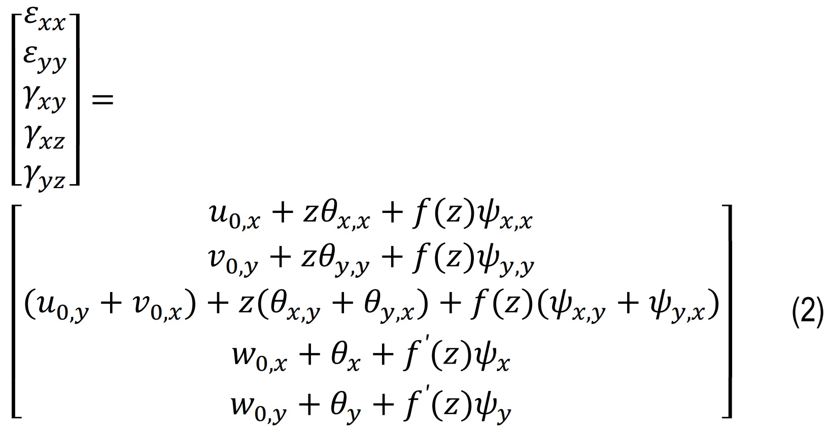
where, u0,x=(∂u0)/(∂x),f'(z)=(df)/(dz). These include contributions from both rotation and non-polynomial shear deformation. Also εx&εyae normal stress in x & y direction, γxy,γxz&γyzbeling shear strain in xy,xz & yz planes correspondingly.
Constitutive relation
Each orthotropic layer of the plate has known elastic constants. The stress–strain relation for a given layer, with one axis of orthotropy aligned with a principal axis, is expressed in Eq.3 [27] and used in the FE formulation.
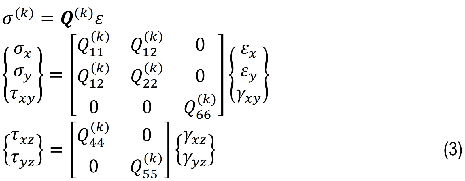
where, σx,σx&τxy are normal stress while τxz&τxz are shear stresses and Qij as shown in Eq.4 comprises the material stiffness coefficients. For orthotropic ply Qij is shown in Eq.4,
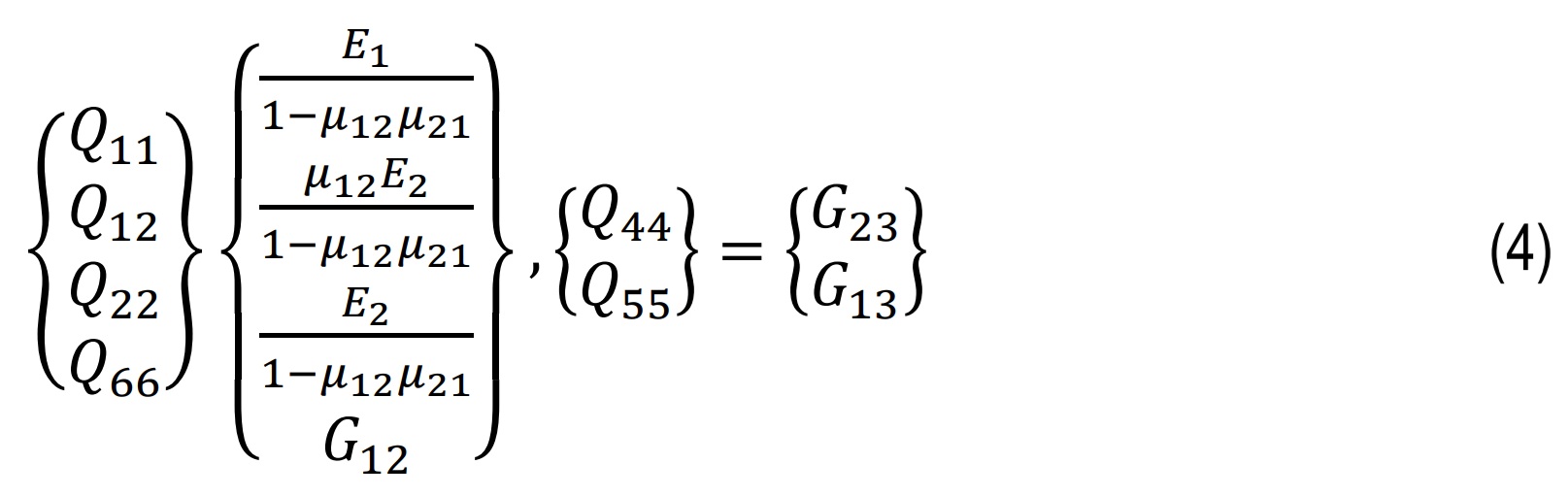
E1,E2are the Young’s moduli along the fiber and transverse directions, G12,G13,G23, the shear moduli, and μ12,μ21 the Poisson’s ratios (μ12)/(E1)=((μ21)/(E2)) these four independent properties define the lamina’s stress–strain behavior under in-plane loading.
Stress resultants and ABD matrices for laminates
Stress resultants (N,M,Q) relate mid-plane strains, curvatures, and transverse shear to laminate forces and moments. ABD matrices combine ply stiffnesses to give membrane (A), coupling (B), and bending (D) behavior of the laminate and are shown in Eq.5. [32]
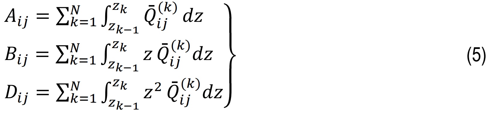
where Ai,Bi&Diare extensional stiffness, bending–extensional coupling stiffness, and bending stiffness correspondingly.
Shear resultants shown in Eq.6 are defined by integrating transverse shear stresses.
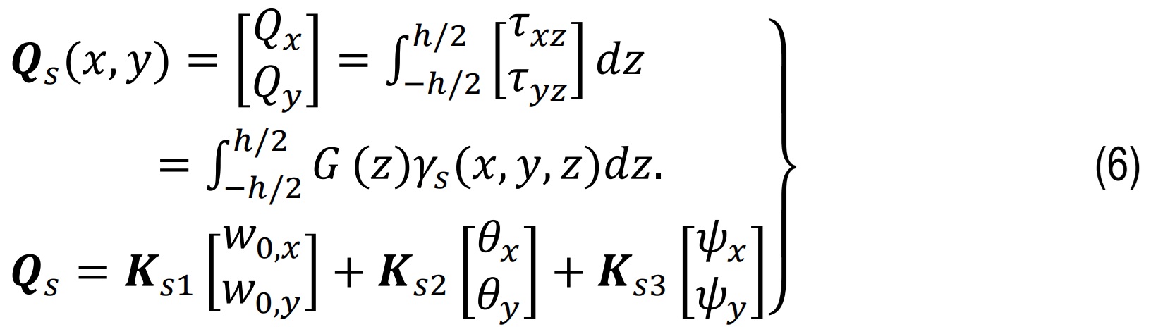
where G(z) contains shear moduli per ply in global form and Ks are precomputed thickness integrals involving G(z) and f'(z).
Finite Element Method
Based on the above theory, a finite element model is formulated using a bilinear isoparametric rectangular element. The validity of the proposed theory, its finite element formulation, and its computational implementation is established through benchmark comparisons with published results. In the examples considered, all laminate have equal thickness, and the plate is discretized using eight-node quadrilateral elements in a quarter-plate model. Stress resultants and through-thickness stresses are extracted at the nearest Gauss points. The mechanical properties of the Graphite-Epoxy lamina-including elastic moduli, shear moduli, Poisson’s ratios, and density-are listed in Eq. 8.
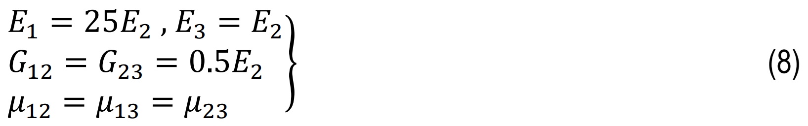
where E1,E2&E3 are Young’s moduli in principal directions. G12,G13 being shear moduli and μ12,μ13&μ23 are Poisson’s ratios.
Isoparametric eight-node serendipity quadrilateral elements Q8 are employed, and the generalized degrees of freedom at each node are approximated using the corresponding shape functions. These elements are used because they offer quadratic interpolation, better bending and stress accuracy, reduced shear locking, and compatibility with the higher-order kinematics of the present model. The displacement field within each finite element is approximated using shape functions Ni(ξ,η) and nodal degrees of freedom d and shown in Eq. 9.
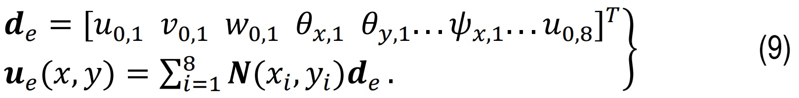
The membrane/bending B matrix Bm maps element nodal displacement vector, de:{εxx,εyy,γxy}T and curvature part included through derivatives of θ while shear B matrix Bs: maps de:{γxz,γyz}T. In this N (x,y) are shape functions of the finite element and u(x,y) being displacement vector at any point in the element.
Element stiffness Matrix
Element stiffness comprises membrane/bending and shear parts and shown in Eq. 10.
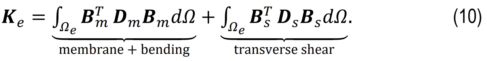
where Dm contains in-plane A, bending D, and coupling B contributions placed in generalized stiffness. The thickness integrals are evaluated to get A,B,D and then used them to assemble the planar constitutive matrix for BmTDmBm.And Ds is the shear constitutive kernel and depends on integrals of G(z) with f'(z) and unity factors.
Boundary conditions
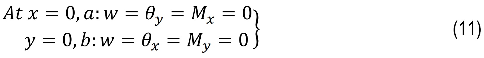
The plate is subjected to simply supported boundary conditions (SSBCs) along all edges, with displacement constraints applied directly, while finite element model naturally satisfies the corresponding bending moment conditions, as shown in Eq. 11.
Transverse loading conditions: SDL and UDL
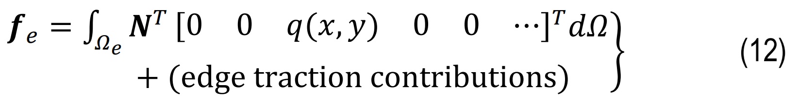
Element nodal force vector due to transverse load q(x,y) is shown in Eq.12 and mentioned in Fig. 2 . The laminated plates are analyzed under two standard transverse loading forms: sinusoidal distributed load (SDL) and uniformly distributed load (UDL).
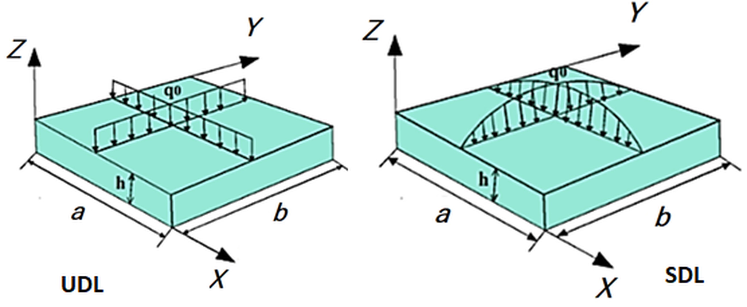
For SDL, the loading typically follows a sinusoidal pattern in both x & y directions, while UDL represents a constant load over the plate surface shown in Eq.13. The first-mode loading condition is considered by taking m=n=1.
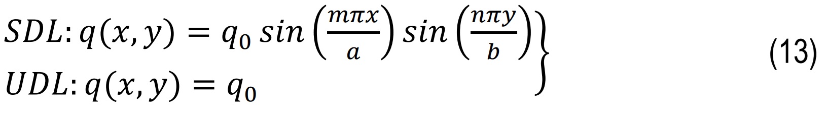
where q(x,y) is a transverse load at point (x,y) while q0 is a reference load magnitude and m,n are integers representing mode number [32].
Post-processing and non-dimensionalization
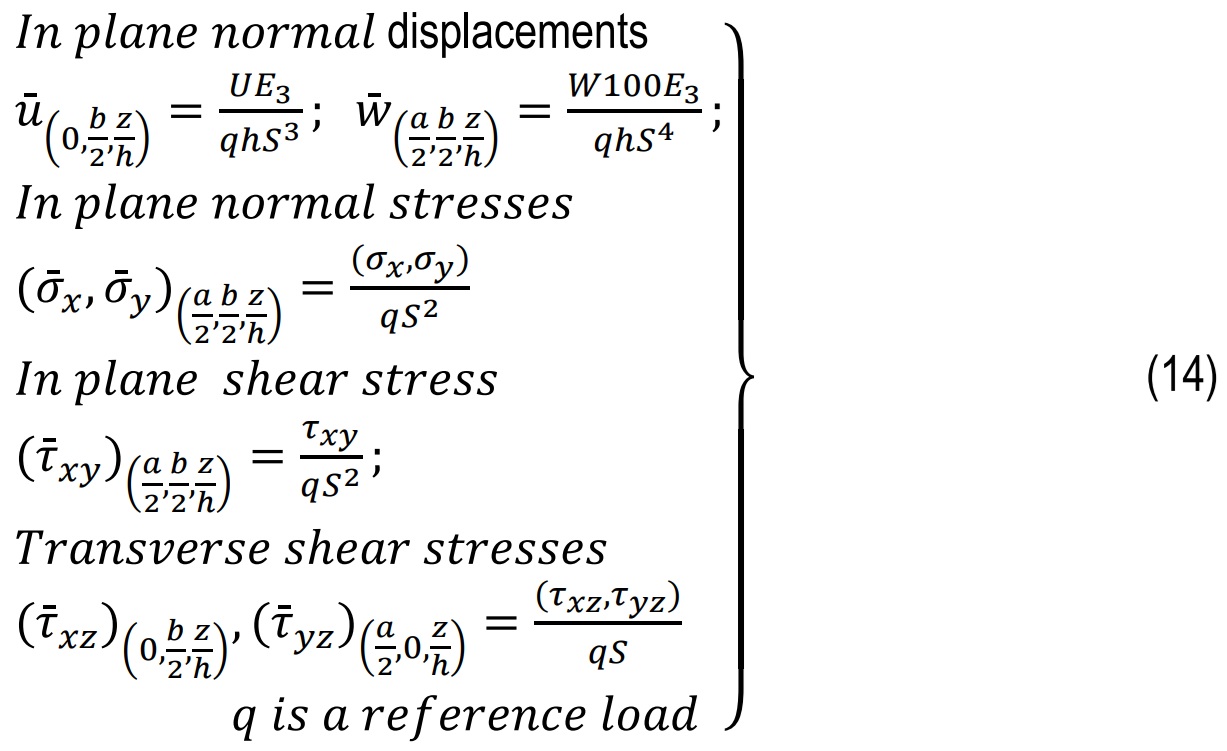
After solving the finite element system, ply-level stresses are extracted through the thickness. Global strains are first computed from the plate kinematics and then transformed into the local material axes for each ply k. Local stresses are obtained using the constitutive relations. To facilitate comparison across different laminates and geometries, stresses and moments are non-dimensionalized as shown in Eq.14. [27]
Results And Discussions
To demonstrate the effectiveness of the present theory, the following numerical examples are solved, and the results are compared with those reported by existing theories in the literature.
Mesh convergence study
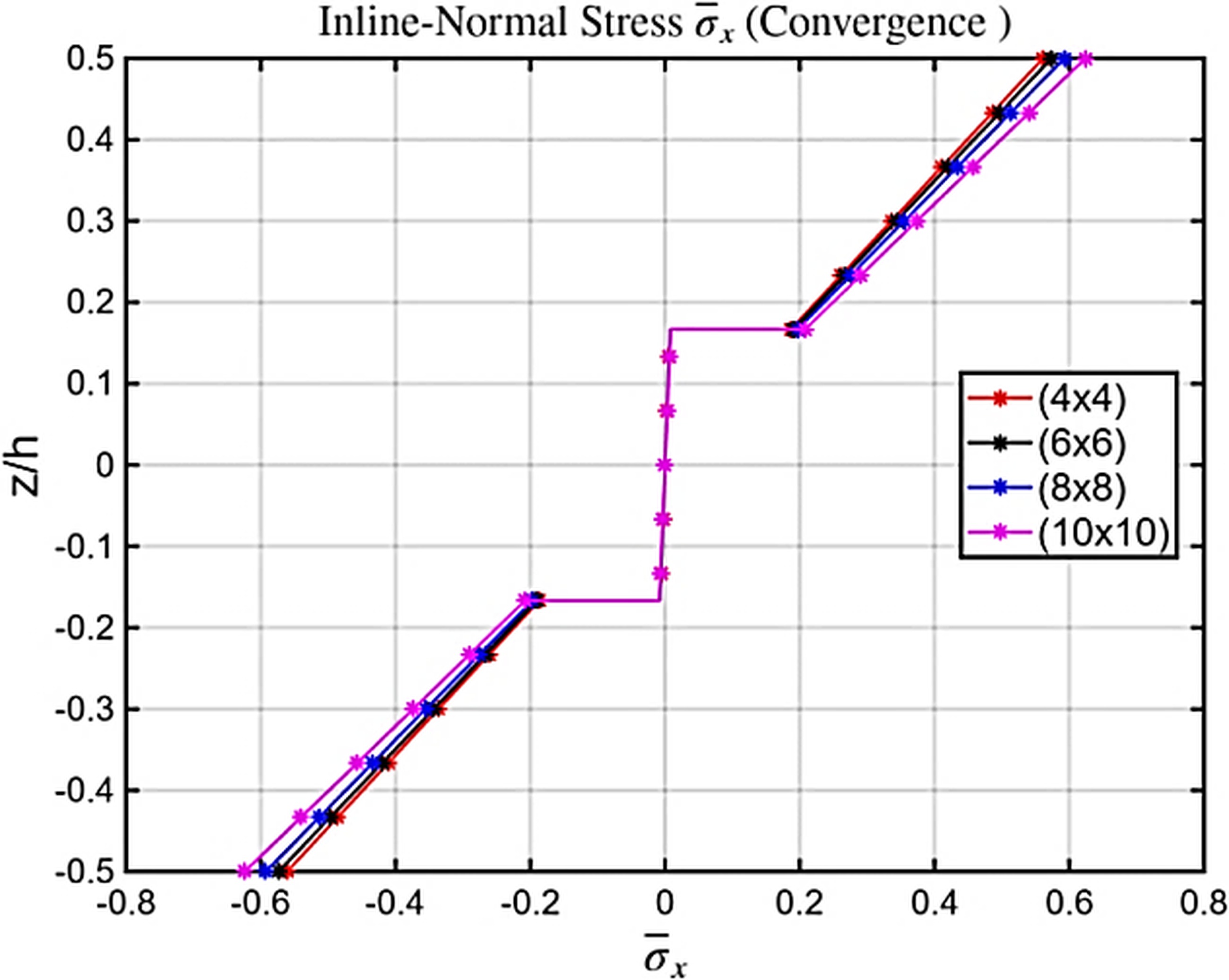
The mesh convergence characteristics of the proposed formulation are evaluated for a aspect ratio ratio of S = 50 under SDL and is shown in Tab. 1 and Fig. 3. The governing equilibrium equations were solved iteratively using a convergence tolerance of three decimal places, and the corresponding in-plane and shear stresses were subsequently extracted. The progression of results across different mesh densities shows a consistent and monotonic improvement, with the solution stabilizing at a 10×10 discretization, which is therefore adopted for all remaining numerical examples.
The convergence trend is further supported by the variation of in-plane normal stresses through the thickness for different mesh sizes. Coarser meshes (4×4&6×6) exhibit noticeable deviations, particularly near the outer surfaces where stress gradients are strongest. In contrast, the results from the (8×8&10×10) meshes are nearly indistinguishable, confirming that additional refinement produces negligible changes. This behavior demonstrates that the formulation is free from shear locking and that the inverse-cotangent shear function ensures a smooth, physically realistic thickness-wise stress distribution. The presence of higher-order in-plane terms contributes to stable and accurate stress recovery throughout the laminate. Collectively, these observations establish the numerical robustness and efficiency of the developed finite element model.
Computational Efficiency and Convergence
The computational efficiency of the proposed finite element formulation is assessed in terms of convergence rate, degrees of freedom (DOFs), and computational time. Owing to the mixed formulation and the reduced continuity requirement, the present HSDT-based model achieves accurate results with significantly fewer DOFs compared to conventional higher-order theories. For instance, in the analysis of a 10×10 laminated composite plate subjected to a uniform transverse load, convergence was achieved using only 1280 DOFs with a total computational time of 0.85 seconds. In contrast, a typical cubic HSDT formulation required 2560 DOFs and approximately 2.5 seconds to reach a comparable level of accuracy. This reduction in DOFs and computational time demonstrates the efficiency of the proposed approach, making it particularly suitable for parametric studies and large-scale analyses of laminated and functionally graded sandwich plates.
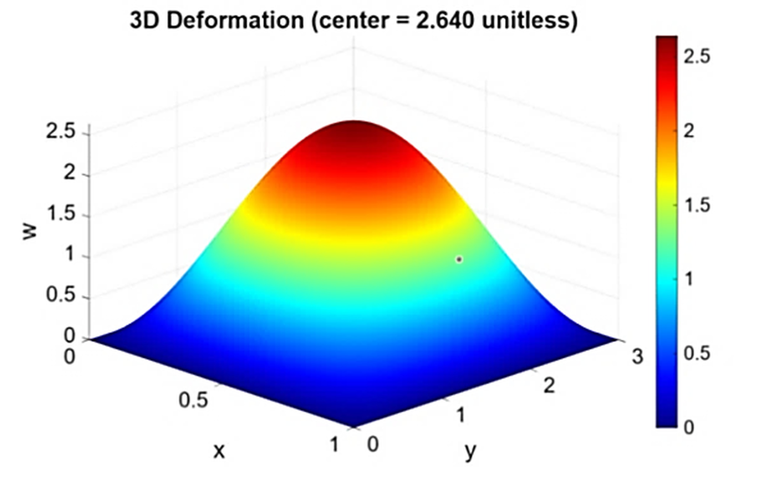
The deformation profile for the same loading case confirms the correct representation of bending behavior. The response remains symmetric, showing a maximum deflection at the plate center consistent with simply supported boundary conditions. The curvature distribution is smooth, and no artificial stiffness is observed, reflecting the capability of the higher-order displacement field to accurately capture both bending and shear effects. For S=4, the non-dimensional mid-plane deflection obtained from the model aligns closely with reference three-dimensional elasticity solutions (w=2.64), indicating a correct global response even for thick plates. The absence of edge irregularities further verifies that the inverse-cotangent function inherently satisfies traction-free shear conditions. Overall, the deformation plots demonstrate that the proposed model accurately represents the bending characteristics of plates subjected SDL.
Bi-directional bending of cross-ply laminated plates
This section presents the application of the developed theory to the bi-directional bending of laminated composite plates. The performance of the proposed model is assessed against well-established benchmarks, including the three-dimensional elasticity solutions of Pagano [33] , the exact solutions of Zenkour [31] for SDL and UDL, and higher-order results reported by Reddy [2] and Sayyad [32]. Material constants in Eq. 8 and non-dimensional parameters in Eq.13 follow the definitions specified.
Two-Layer (0/90) anti-symmetric cross-ply plates
A detailed comparison of non-dimensional displacements u(h/2), w(0) and stresses σx(h/2),σy(h/6),τxy(h/2), τxz(0)&τyz(0) for the two-layer (0/90) laminate shown in Tab. 1- 4 indicates that the proposed nICSDT consistently aligns with three-dimensional [31] elasticity predictions. The transverse deflectionw(0) is slightly greater than that predicted by FSDT and CLPT [1] but closely matches results lireatures [2 &32], particularly for S = 4, and maintains accuracy at higher span ratios. The in-plane stress components τxy(h/2) also show excellent agreement with the present model capturing the correct magnitude and variation across the laminate thickness.
Differences from FSDT arise largely due to the reliance of Mindlin’s theory on shear correction factors, which tend to underestimate or overestimate shear contributions depending on plate thickness. Similarly, CLPT shows significant deviation because it completely neglects transverse shear. The proposed model also offers accurate predictions of transverse shear stresses τxz(0)&τyz(0), especially when computed using equilibrium relations, demonstrating close proximity to exact solutions. This confirms the ability of the inverse-cotangent function to reproduce realistic shear distributions without artificial adjustments. Increasing the span ratio leads to higher deflections and stress magnitudes, a trend that the present formulation captures reliably. Overall, the results highlight the robustness and accuracy of nICSDT for asymmetric cross-ply configurations.
Three-Layer (0/90/0) symmetric cross-ply plates
For the symmetric three-layer (0/90/0) laminate, the proposed formulation continues to exhibit excellent correlation with exact 3-D elasticity solutions across all loading and geometric configurations.
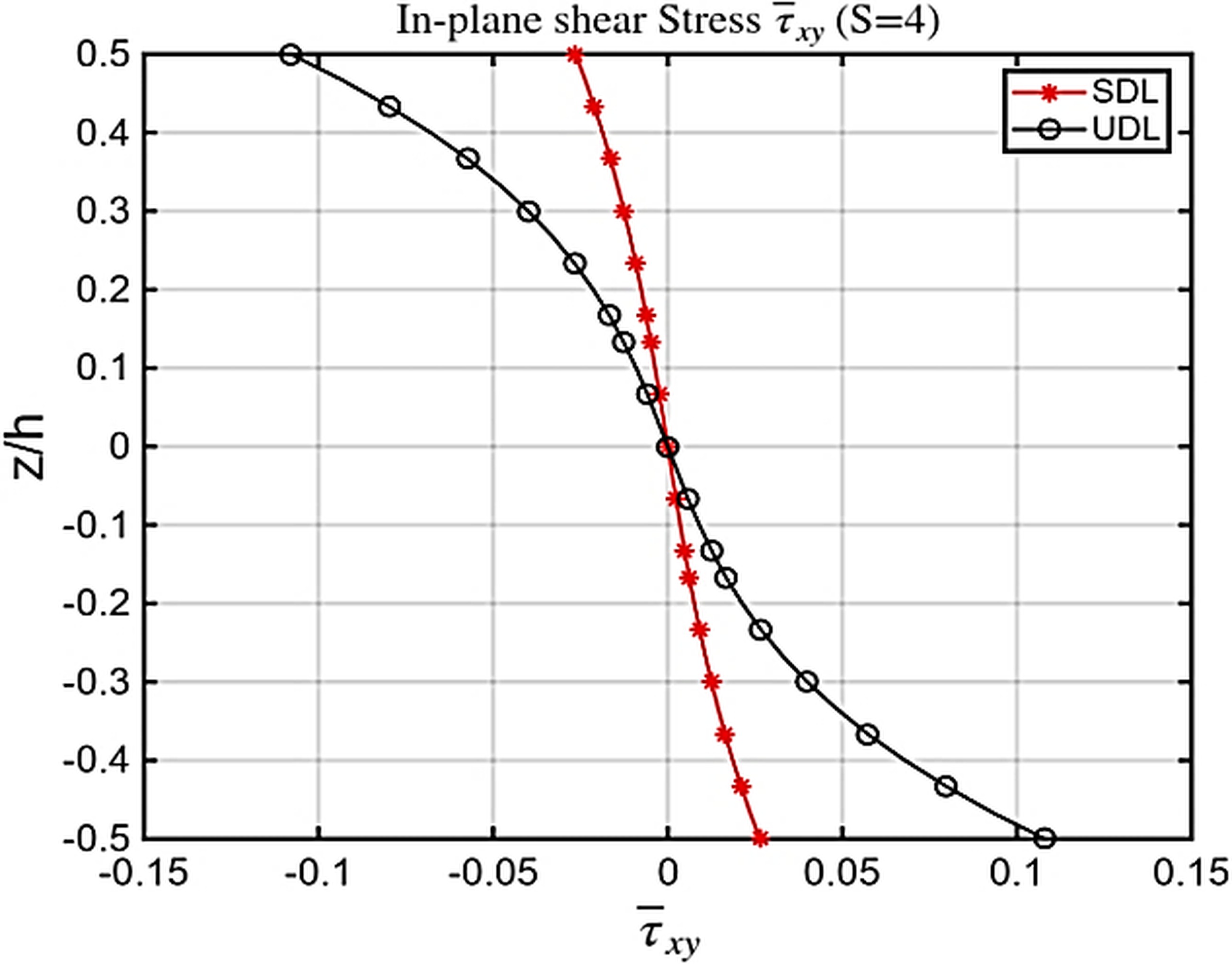
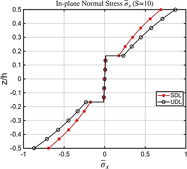
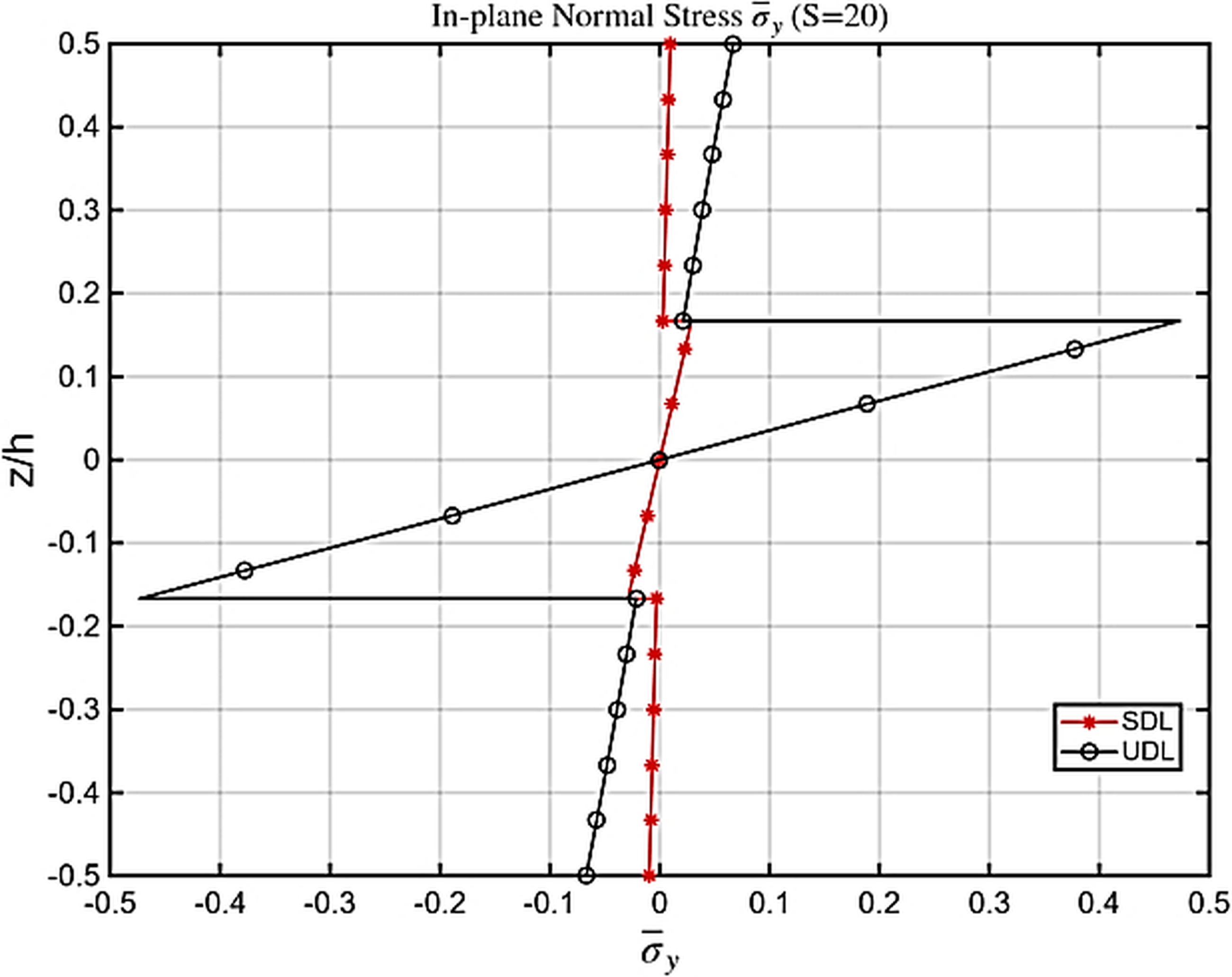
Both transverse and in-plane displacements predicted by nICSDT fall within the expected range of higher-order solutions, confirming that the proposed theory effectively captures the influence of symmetry on stiffness and stress behavior. Classical theories remain inadequate for these cases, substantially underestimating deflection and failing to represent the correct shear stress variation. For both sinusoidal (SDL) and uniformly distributed loads (UDL) at span ratios S=4 and S=10 (Tab. 5-8), the transverse displacements predicted by the nICSDT are slightly lower than those reported in [32] and [2], yet remain highly accurate. In contrast, the classical theory [3] significantly underestimates displacements, particularly for thicker plates, underscoring the necessity of higher-order models. The in-plane normal stresses σx(h/2)&σy(h/2) from nICSDT exhibit excellent agreement with exact solutions and other higher-order theories, whereas [1] and [3] under predict these stresses, especially σx, due to their limited ability to capture multi-layer bending effects. Transverse shear stresses τyz(0)are slightly lower than [1] when computed via constitutive relations but align closely with exact 3D solutions [31] when determined through equilibrium equations [3], however, fails to capture shear stresses entirely. Increasing the span ratio from S=4 to S=10 reduces transverse displacements relative to plate thickness and slightly lowers in-plane stresses—trends accurately captured by nICSDT, demonstrating its robustness across varying slenderness ratios. Additionally, UDL generates larger transverse displacements and slightly higher in-plane stresses compared to SDL, and the proposed theory effectively captures both the quantitative and qualitative differences. Overall, nICSDT consistently provides results closest to the exact 3D solutions, with deviations within 2–6%, outperforming [1] in stress predictions and [3] in deflection estimates, while results from [32] and [2] also remain reliable for symmetric laminated plates. Figs. 5-9 show variation stresses through the thickness of a (0/90/0) laminated plate under SDL & UDL at different aspect ratio. In Fig. 5 the τxy at top and bottom surface of plate in case of UDL found 5 times more than that of SDL. This is essentially due to boundary shear transfer Under UDL, the entire uniform load is transferred through the supports, creating much larger boundary shear forces, which results in significantly higher surface shear stresses. In contrast, SDL is zero at the edges, so very little shear is carried near the supports, giving much smaller top and bottom shear stresses. Similarly Figs.5-9. shows Variation of stresses through the thickness of plate in case of SDL are almost 1.5-2 times more than that of SDL. This is due to fact that SDL concentrates the load toward the center of the plate (center-concentrated curvature.), producing higher bending moments and sharper curvature compared to UDL.
Tab. 1
Non-dimensional displacements and stresses for a (0/90) plate under SDL (S=4)
Tab. 2
Non-dimensional displacements and stresses for a (0/90) plate under UDL (S=4)
Tab. 3
Non-dimensional displacements and stresses for a (0/90) plate under SDL (S=10)
Tab. 4
Non-dimensional displacements and stresses for a (0/90) plate under UDL (S=10)
Tab. 5
Non-dimensional displacements and stresses for a (0/90/0) plate under UDL (S=4)
Tab. 6
Non-dimensional displacements and stresses for a (0/90/0) plate under SDL (S=10)
Tab. 7
Non-dimensional displacements and stresses for a (0/90/0) plate under UDL (S=4)
Tab. 8
Non-dimensional displacements and stresses for a (0/90/0) plate under UDL (S=10)
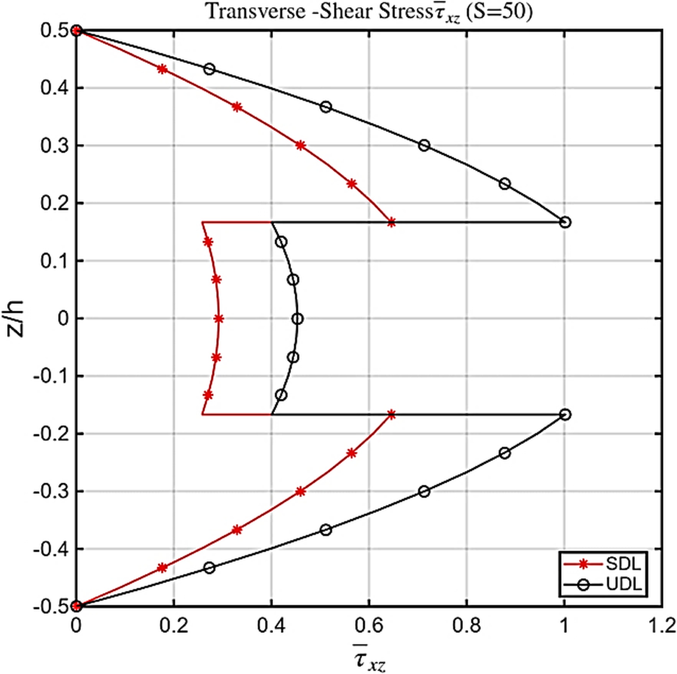
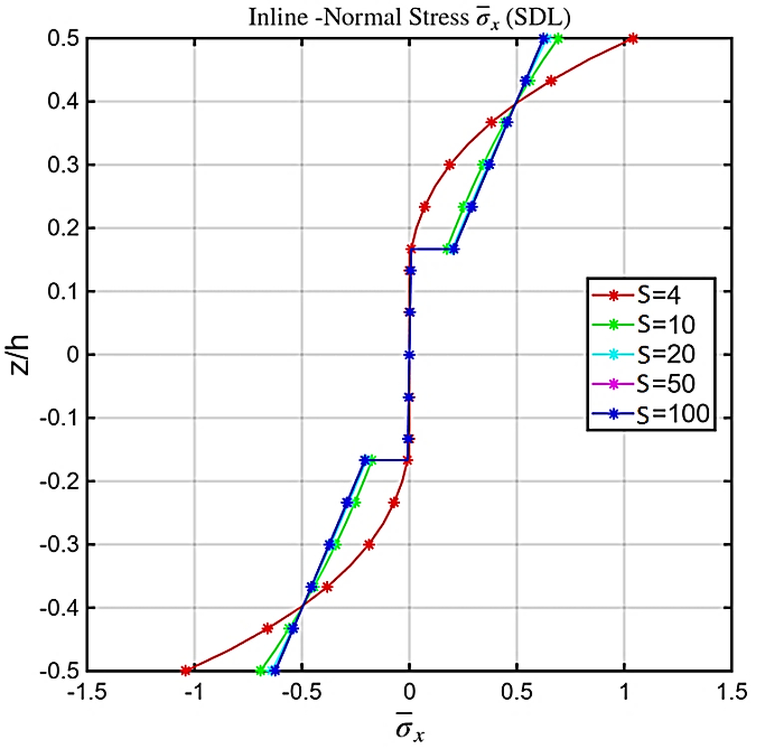
The symmetry of (0/90/0) laminate captured in all plots. The shear stress is zero at surfaces validates cotangent function. Fig. 9-11. Shows the plot explores the effect of increasing aspect ratio. For S = 4 (thick plate), stresses are higher and transverse-shear effects dominate, producing greater through-thickness curvature. As S increases to 10, 20, and 50, stresses decrease as shear influence diminishes. For S = 100, the response approaches the thin-plate limit, with flatter stress profiles and minimal shear effects. The theory smoothly shifts from thick-plate behavior, where shear dominates, to thin-plate behavior, where bending dominates. Figs. 9–11 show that the proposed model accurately captures shear-dominated behavior at low S and the expected bending-dominated response at high S.
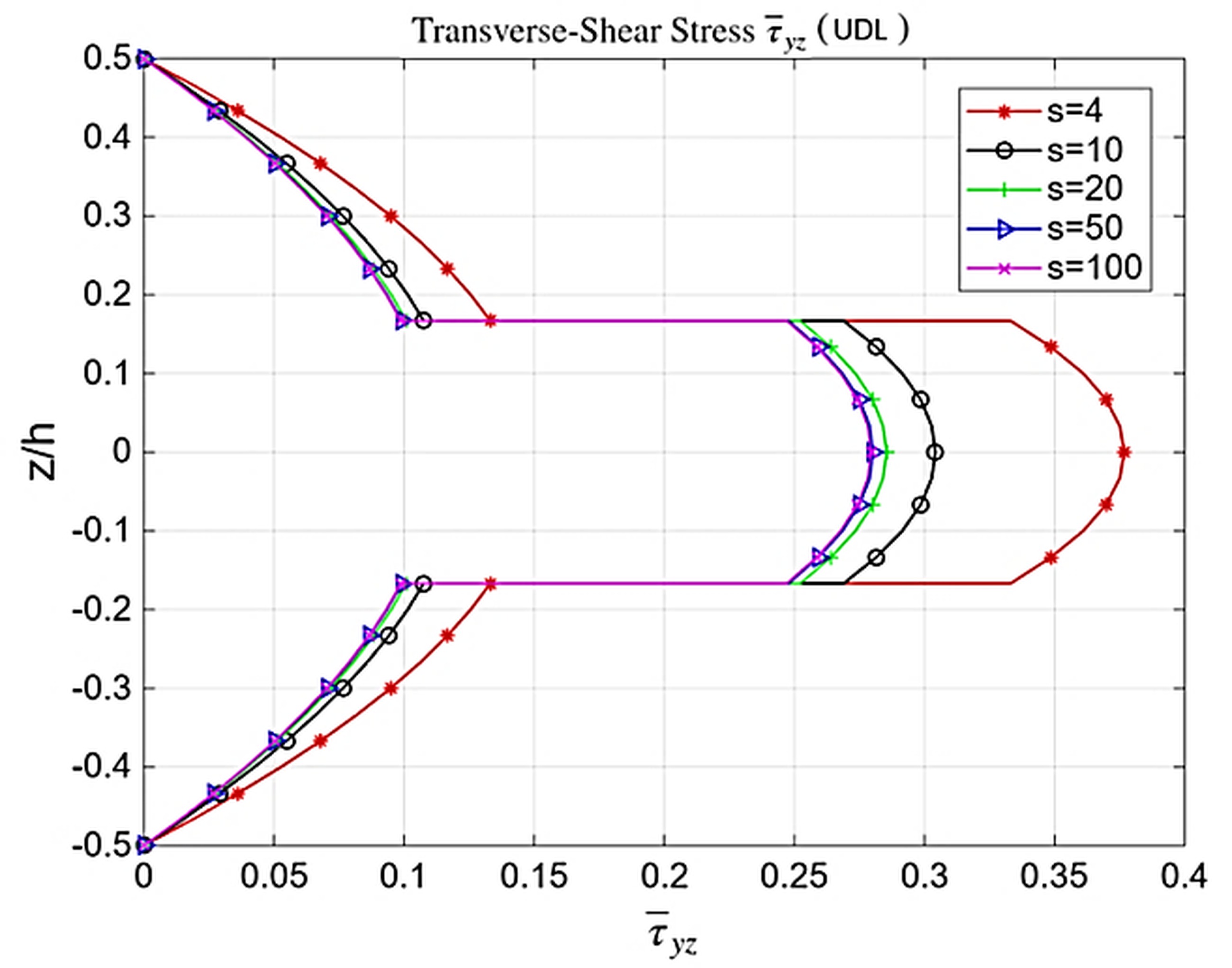
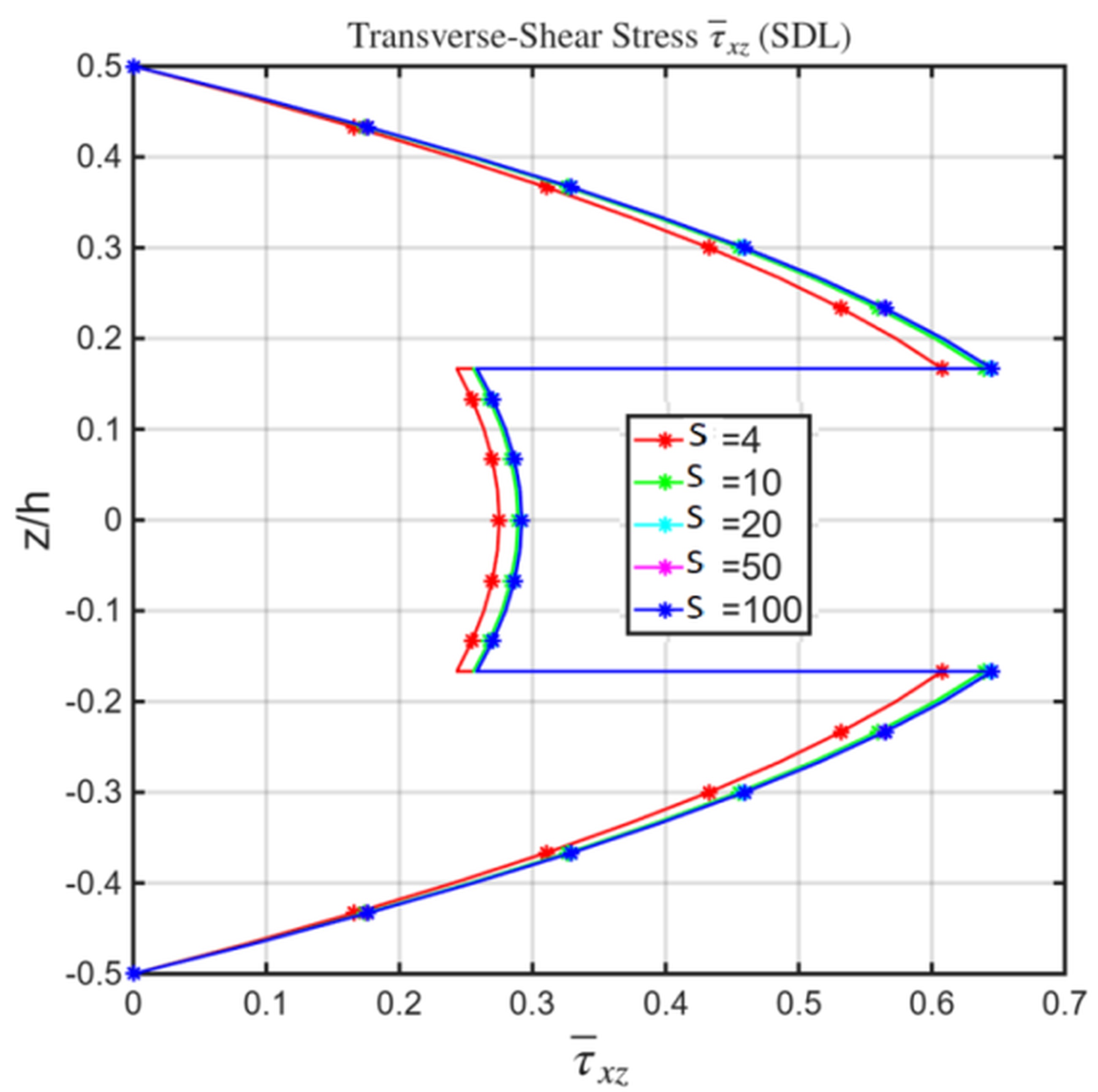
The model demonstrates the proper shift from shear-dominated response at low S, characteristic of thick plates, to bending-dominated response at high S, as expected for thin-plate behavior.
Conclusion
A new inverse-cotangent higher-order shear deformation theory (nICSDT) and its C⁰-continuous finite element implementation have been presented. The formulation eliminates the need for shear correction factors, ensures numerical stability, and achieves near three-dimensional accuracy in the static bending analysis of laminated composite rectangular plates. Extensive validation demonstrates the robustness, accuracy, and efficiency of the proposed model, confirming its applicability to both shear- and bending-dominated regimes. Future work will focus on extending the formulation to dynamic analysis, thermal loading, buckling, post-buckling, and delamination problems. Moreover, the proposed formulation exhibits improved computational efficiency by achieving convergence with fewer degrees of freedom and reduced computational time compared to conventional HSDT models.