INTRODUCTION
Conversion of wind kinetic energy into usable electrical energy, i.e. wind-induced vibration energy harvesting (WIVEH), is a promising branch of renewable technologies. The process is based on the principles of fluid-structure interaction dynamics, where stochastic wind energy is converted into periodic vibrations of mechanical structures and then into electrical energy via piezoelectric transducers. The WIVEH is a potential power source for a wide range of low-power devices, such as Internet of Things (IoT) terminals, wireless sensors, and microelectronics. Its implementation can eliminate the dependence on traditional chemical batteries, especially in applications requiring long-term, maintenance-free operation, including remote locations such as bridges, canals, high-rise buildings, and medical implants. The basis of the WIVEH systems is the coupled dynamics of gases (aerodynamics) and various physical phenomena (multiphysics). Aerodynamic instabilities such as vortex-induced vibrations (VIV), galloping and flutter play a key role in initiating and sustaining vibrations of mechanical structures (or structural vibrations). In particular, non-streamlined elements (bluff-bodies) are used, which, placed at the free end of the beam, generate aerodynamic instabilities. When the wind flows around the bluff body, it generates aerodynamic forces that excite the beam vibrations, acting as an aerodynamic exciter. The generated mechanical energy is then converted into electrical energy by piezoelectric materials, which respond to mechanical deformations by generating an electric charge [1, 2].
The widespread application of WIVEH encounters obstacles, the main one being low electromechanical conversion efficiency, especially in one-degree-of-freedom (1-DOF) configurations. These simple systems are characterized by inherent bandwidth limitations (effective only in a single resonant frequency), which makes them incompatible with broadband and stochastic wind characteristics in the natural environment. The answer to these limitations is the research in the field of WIVEH, which is concerned with the design and analysis of more complex systems, including systems with two-degrees-of-freedom (2-DOF) and systems integrating additional nonlinear elements such as magnetic coupling. These complex configurations provide improved performance of EH systems. 2-DOF VIVPEH (Vortex-Induced Vibration Piezoelectric Energy Harvester) systems are characterized by wider operating bands, which is manifested by the presence of two separate "lock-in" regions. However, the introduction of nonlinear magnetic coupling significantly reduces the start-up speed, which is crucial for efficient operation at low wind speeds [3, 4]. The WIVEH research focuses on strategic exploitation of system nonlinearities and increased design complexity. The goal is to exploit the nonlinear dynamic response of the system, rather than its damping, to achieve increased energy harvesting efficiency over a wider range of wind parameters. These nonlinearities are not limited to the geometric effects of large deflections, but also include nonlinear coupling of piezoelectric materials to the power harvesting circuit and nonlinearities resulting from the material properties of PZT. Understanding and exploiting these nonlinearities, for example in the form of bistability or chaotic oscillations, can provide significant benefits in broadband harvesting, which is crucial for efficient operation in wind variables [5, 6].
In this paper, we experimentally investigate piezoelectric cantilever energy harvesting excited by vortex-induced vibrations in a low-speed open wind tunnel, focusing on the role of bluff body geometry in determining vibration dynamics and electrical output. The study aimed to observe the occurrence of aerodynamic phenomena such as: galloping at low wind speeds and post‑lock‑in amplitude decay (desynchronization) at higher speeds; the strengthening of vortex activity with increasing air speed, up to a certain range; the effect of the presence of cuboid edges and their absence in cylinders; the presence of flat vertical walls; possibility of fluttering due to significant difference in dimensions of bluff-body height and beam width. Three bluff body configurations are compared: a single-cylinder, two-cylinders connected by a flat wall, and a cylinder–cuboid hybrid. Beam deflections are measured using a laser vibrometer, while electrical signals from the piezoelectric transducer are analyzed with data acquisition systems. Continuous wavelet transform (CWT) and statistical evaluation are applied to characterize frequency content, lock-in phenomena, and nonlinear response across a wide range of airflow velocities. The results demonstrate that while the two-cylinder geometry maximizes energy harvesting efficiency through strong VIV lock-in, it suffers from structural instability at higher wind speeds. In contrast, the cylinder–cuboid hybrid achieves stable operation with reduced variability, making it more suitable for practical applications in broadband, low-speed airflow environments.
FUNDAMENTALS OF AERODYNAMIC EXCITATION MECHANISMS AND PIEZOELECTRIC ENERGY HARVESTING
In WIVEH systems, three main aerodynamic excitation mechanisms play a key role [7, 8, 9, 10]:
Vortex-Induced Vibrations (VIV): This mechanism occurs when vortices periodically shed from the edge of a bluff body, generating a variable aerodynamic force that stimulates vibrations in the structure. The system oscillates with a large amplitude when the shedding frequency of the vortices is close to the structure's natural frequency, leading to a "lock-in" phenomenon, i.e. synchronization of the vibration frequency with the excitation frequency. Unlike galloping, the amplitude of VIV vibrations does not increase monotonically with wind speed, providing a natural protection mechanism for the system against damage at high wind speeds [11, 12].
The fluctuating lift force due to vortex shedding can be approximated as:

where:
ρf – fluid density,
CL – fluctuating lift coefficient (typically 0.1-0.3 for cylinders),
L – length of the cylinder.
Lock-in Phenomenon: When the vortex shedding frequency approaches the natural frequency of the structure, "lock-in" occurs, leading to resonance and amplified vibrations.
fv ≈ fn → resonance
Galloping: This is an aeroelastic phenomenon characterized by large amplitude oscillations at low frequencies. It is generated by a negative slope of the lift vs. angle of attack curve, which creates a negative aerodynamic damping effect, causing increased deflection and allowing the structure to absorb energy from the airflow. In the context of energy recovery, galloping is a desirable phenomenon because it leads to large deflections of the piezoelectric beams and, consequently, higher electrical power output.
The angle of attack, leading to self-excited oscillation is defined by Den Hartog Criterion. Galloping instability occurs when:

where:
CL – lift coefficient,
CD – drag coefficient,
α – angle of attack.
The wind speed at which galloping begins (Critical Galloping Velocity) is:

where:
m – mass per unit length,
ζ – damping ratio,
ωn – Natural angular frequency,
ρa – Air density,
D – width facing the wind,
H – height perpendicular to wind.
The amplitude of galloping response oscillations can be estimated as:

Galloping typically produces larger amplitude oscillations than vortex-induced vibrations, making it potentially more effective for energy harvesting.
Flutter: This is a form of aeroelastic instability characterized by coupled bending and torsional vibrations, also used in energy recovery.
Various aerodynamic excitation mechanisms, such as vortex and galloping, can be combined in a single system operation to increase power output at low wind speeds and extend the operational range. The geometry of the bluff body plays a crucial role in generating power in wind-driven systems (for aerodynamic efficiency). Different bluff body shapes induce different flow patterns and aerodynamic forces. Experimental comparisons of four bluff body shapes presented in [13] showed that the triangular cuboid (triangular column) exhibited better aerodynamic stability, achieving an output voltage of 11.6 V at a wind speed of 7.0 m/s. Studies of shapes such as rhomboid, square, and triangular showed that the rhomboid bluff body generated higher voltage values in VIV experiments, which was explained by optimal flow patterns and minimum wake pressure [14]. Rectangular bluff bodies have also been observed to be most effective at converting vibrations to electrical energy at specific frequencies, which allows such solutions to be dedicated to applications in urban environments, such as ventilation systems (HVAC). Based on the research presented in the literature, it can be concluded that aerodynamic shape optimization, including the use of symmetrical configurations with convex trailing edges and concave top and bottom surfaces, can significantly reduce required wind speeds and increase power generation.
Optimizing bluff bodies for WIVEH goes far beyond simply selecting a basic geometric cross-section. Complex surface modifications (e.g., attachments, ribs), internal structural designs (e.g., cutouts), and potentially multibody configurations must be considered. For example, adding "two small rods" to a cylinder can significantly impact voltage output, and the concept of a "hyperstructure" on the bluff body surface improves low-wind performance. These detailed design elements are crucial for fine-tuning aerodynamic properties, influencing vortex shedding frequencies, optimizing pressure distribution, and ultimately increasing energy harvesting efficiency, especially in challenging low-wind conditions. This represents a shift toward highly complex aerodynamic surfaces, potentially inspired by biomimetics, rather than relying on simplified prismatic forms. Even subtle modifications to a bluff body's surface can significantly alter its aerodynamic properties. Corrugated bluff bodies improve low-wind performance, increasing average tension by 182% and power by 36.2% at 2 m/s compared to smooth bluff bodies, and also provide stable vibration [15]. In the study conducted by the authors, the surface of the solids was corrugated with a length of 0.2 mm, typical for 3D printers printing with the FDM technique.
Piezoelectric transducers (PZT) play a crucial role in the conversion of mechanical energy into electrical energy. By attaching PZT elements to the beam walls, the kinetic energy generated by beam vibrations is transmitted directly to the piezoelectric material, ensuring high efficiency in converting mechanical energy into electrical energy. PZT materials, particularly types such as PZT-5A and PZT-5H, are preferred due to their good piezoelectric properties, surpassing other materials such as PVDF (Polyvinylidene Fluoride) and MFC (Macro-Fiber Composite) in generating electrical current. According to the results presented in [16, 17], PZT-5A demonstrated exceptional efficiency, achieving 98.79% frequency response and 98.87% load response. PZT is distinguished by its ease of production, a variety of thin plate sizes and shapes, a wide bandwidth, and a high natural frequency, enabling versatile applications in energy recovery. A disadvantage of PZT materials is their susceptibility to depolarization and cracking upon significant deformation. Therefore, in wind-driven systems, it is advisable to control aerodynamic phenomena that cause large beam deflections or to choose the appropriate PZT element assembly. Piezoelectric materials generate electric charge when mechanically strained, allowing conversion of mechanical vibration energy into electrical energy. The coupled electromechanical behavior of piezoelectric materials is described by:

where:
S – strain,
T – stress,
E – electric field,
D – electric displacement,
sE – elastic compliance at constant electric field,
d – piezoelectric strain coefficient,
εT – permittivity at constant stress.
For a piezoelectric element bonded to a beam, the voltage generated in open-circuit is:

where:
d31 – Piezoelectric strain coefficient
Yp – Young's modulus of piezoelectric material
tp – Thickness of piezoelectric layer
ε – Strain in the piezoelectric layer
ε33 – Dielectric constant
The average power output across a resistive load is:

For optimal power transfer, the load resistance should match the internal impedance of the piezoelectric element:

where:
ω – angular frequency of vibration,
Cp – capacitance of the piezoelectric element.
The time to charge a capacitor to 63% of the final voltage is:

where:
R – equivalent resistance,
C – capacitance.
THE BEAM MODEL
The system model is based on a flexible cantilever beam with a rectangular cross-section, is described by the following governing equation of motion:

where:
E – Young's modulus,
I – second moment of area
(
ρ – density of the beam material,
A – cross-sectional area,
c – damping coefficient,
F(x,t) – external force.
The natural frequencies of a cantilever beam are given by:

where βₙL values are:
The mode shapes for a cantilever beam are:

where:

EXPERIMENTAL SETUP
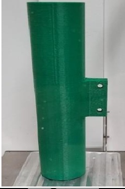
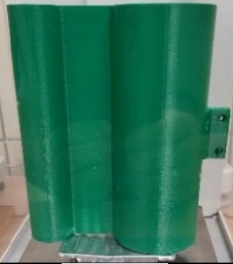
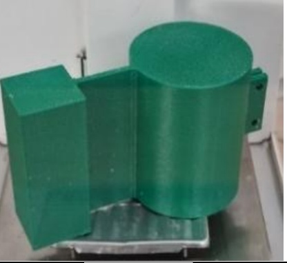
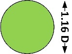
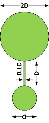
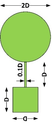
In response to the challenges presented in the theoretical section, several versions of a wind energy recovery system were developed and tested in a wind tunnel during vibration excitation over a wide range of wind speeds. Because the aerodynamic phenomena studied are characterized by high variability due to the presence of nonlinearities, and to illustrate the impact of nonlinearities, comparative studies were conducted on systems with modified designs within a narrow range. Specifically, the behavior of systems equipped with bluff bodies with three different bluff body shapes (bluff bodies) was studied. Configurations with a single-cylinder, two-cylinders connected by a flat wall, and a cylinder-cuboid connected by a vertical wall were compared. The experimental setup in the open-wind tunnel with cross-section dimensions of 0.3 x 0.3 [m] and controlled air speed from 0 to 15 [m/s], used for experimental tests, is presented in Fig. 1 and Fig. 2.
The tested cases of the bluff bodies and piezo cantilevers are given in Table 1 and Table 2.
The cantilever’s material mechanical properties are collected in Table 3.
The tested macro-fibre composite (MFC) as the energy harvester is described in Table 4.
The tested setups and configurations in the wind tunnel are presented in Fig. 3.
Data acquisition was performed using the laser vibrometer sensor LG10Ag5PUQ with a resolution of 12 m, a supercapacitor BIGCAP (0.1F, 5.5 VDC), voltage conditioner EH301A, resistor 1 kOhm and data acquisition card National Instruments NI USB-6341 (resolution 16bit, sampling 500 kS/s per channel). Figure 4 shows a diagram of the connection of the measuring track elements.
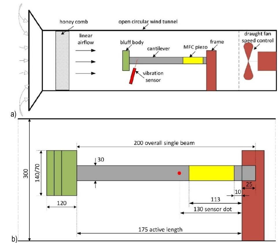
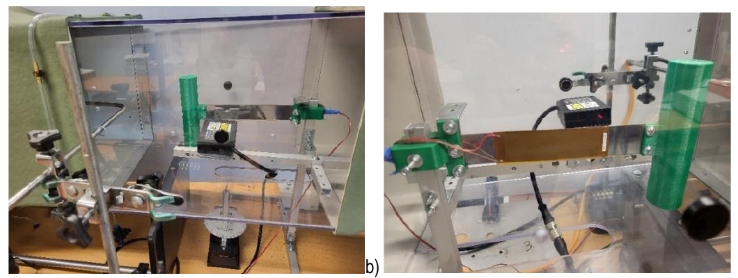
Fig. 2. Example experimental configuration of piezo cantilever with laser vibration sensor in the wind tunnel. Views from both sides a) and b)
Tab. 1.
Bluff bodies' dimensions and weights, where the main dimension D = 30 mm
Tab. 2.
Cantilever dimensions and weight
| Cantilever | Name | Mass [g] | Dimensions w×d×h [mm] | Material |
|---|---|---|---|---|
 | The beam with MFC 14D15-034I | 27.30 | 30×1×200 | stainless-steel 316L |

Fig. 3. The wind tunnel experiment setups: a) single short beam with cylinder, b) single short beam with two-cylinders, c) single short beam with cylinder-cuboid
Tab. 3.
Physical and mechanical properties of the cantilever beam, stainless-steel 316L austenitic
| Parameter | Value |
|---|---|
| Density/(kg/dm³)20℃ | 8.00 |
| Electrical Resistivity/(Ω·mm2/m)20℃ | 0.74 |
| Modulus of Elasticity(kN/mm2)20℃ | 193 |
| Yield Strength RP0.2/MPa | ≥180 |
| Tensile Strength Rm/MPa | ≥485 |
Tab. 4.
Parameters of the macro-fiber composite piezo [18]
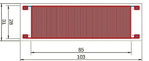
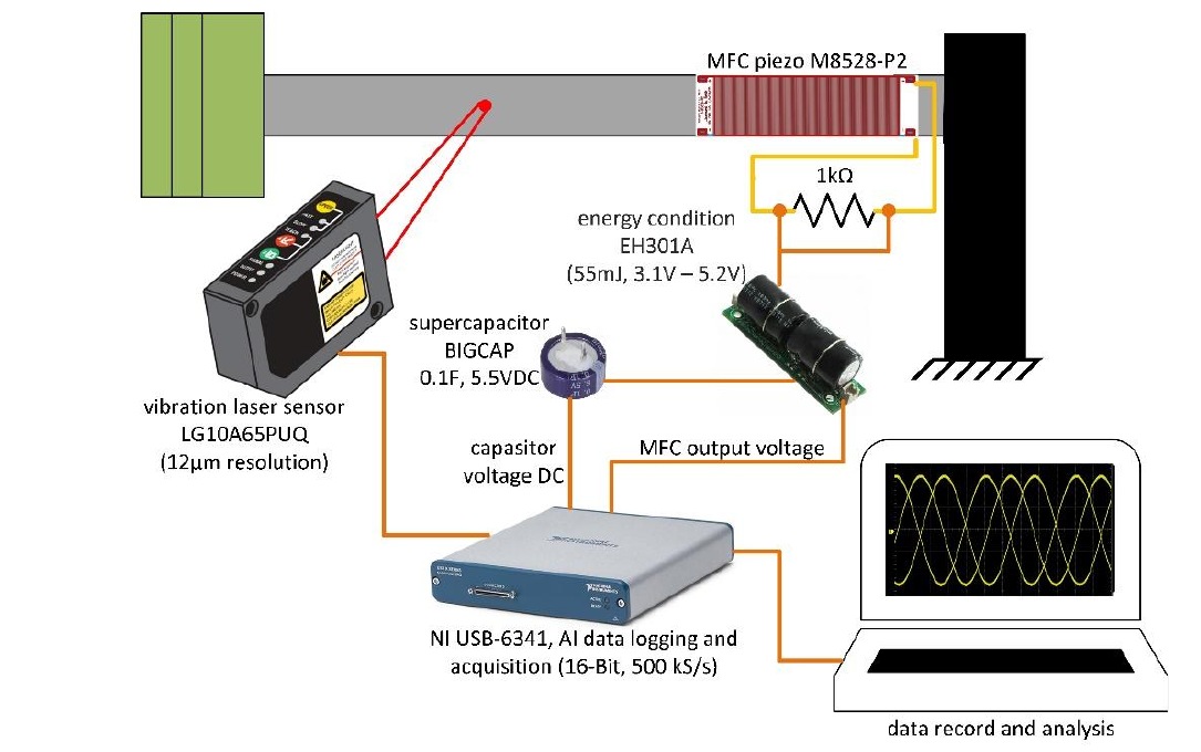
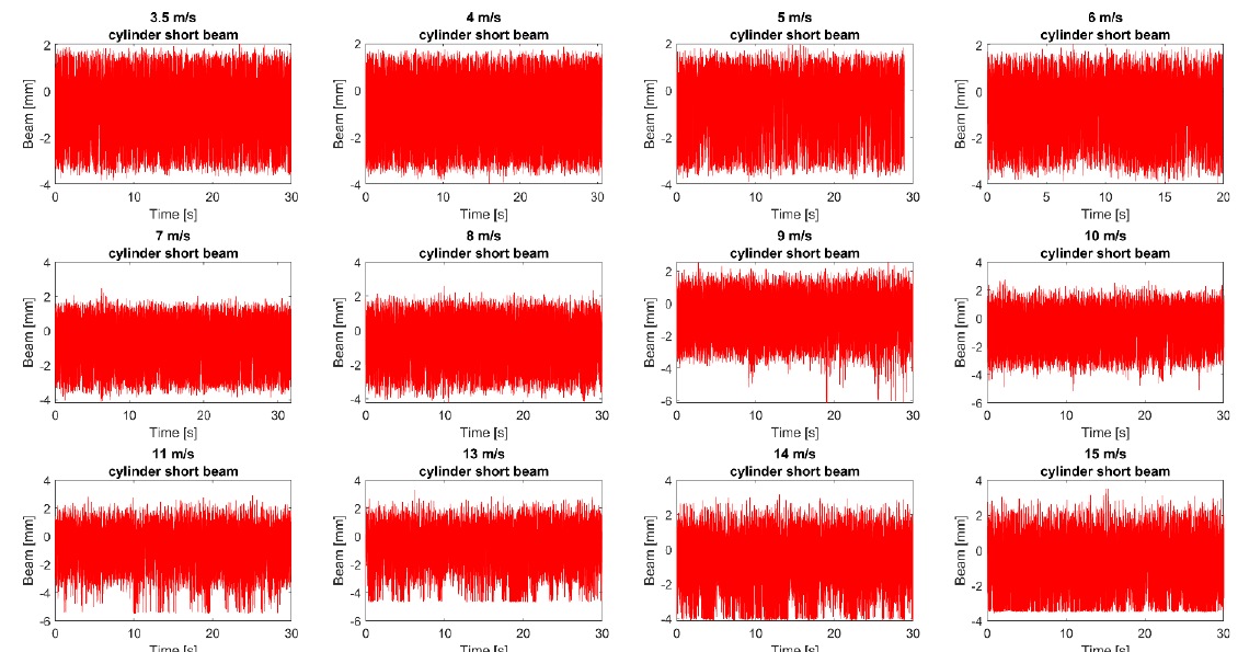
Fig. 5. The deflection of the beam with the single-cylinder during excitation by air at velocities from 3.5 to 15 [m/s]
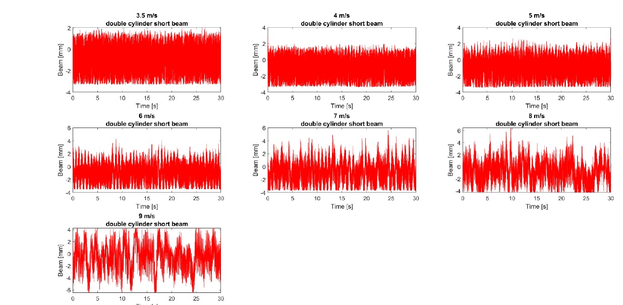
Fig. 6. The deflection of the beam with two-cylinders during excitation by air at velocities from 3.5 to 9 [m/s]
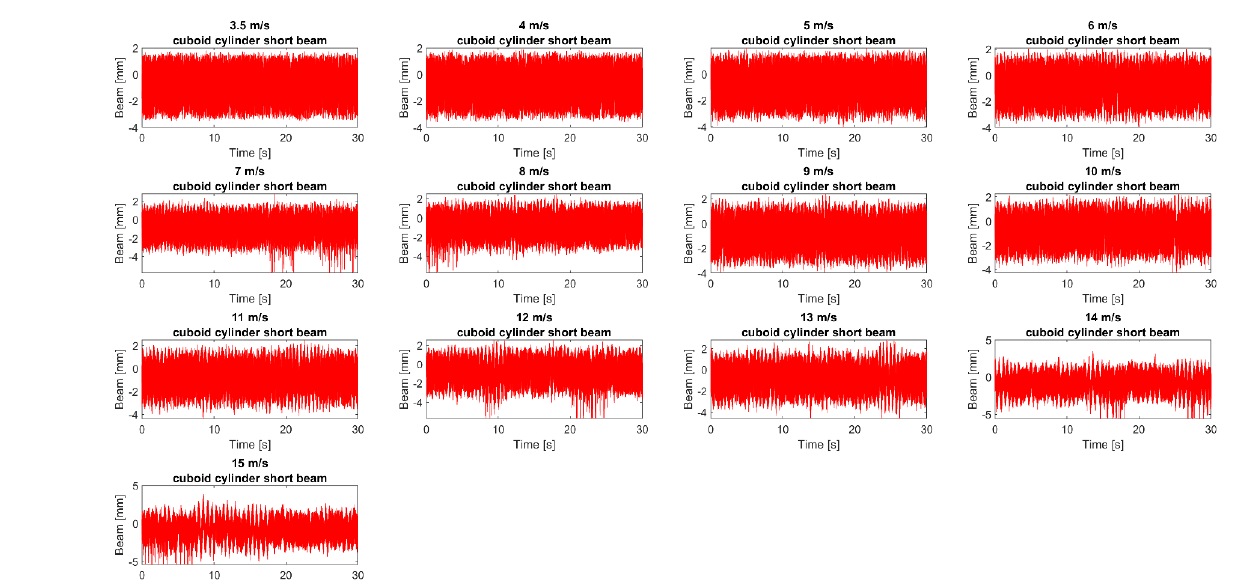
Fig. 7. The deflection of the beam with the cylinder-cuboid configuration during excitation by air at velocities from 3.5 to 15 [m/s]
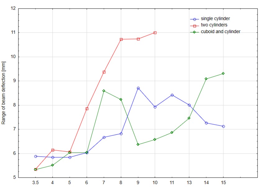
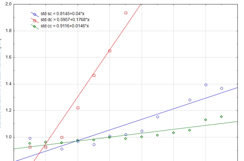
Fig. 9. Normalized standard deviation of the beam deflection for air excitation at speeds from 3.5 to 15 [m/s] of three systems, where sc -single-cylinder, dc – two-cylinder, cc – cylinder-cuboid
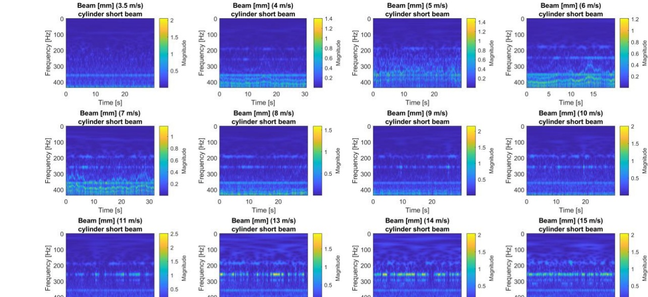
Fig. 10. Continuous wavelet transform of the beam deflection with single-cylinder during excitation by air at velocities from 3.5 to 15 [m/s]
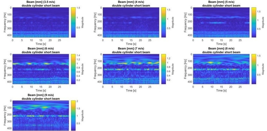
Fig. 11. Continuous wavelet transform of the beam deflection with two-cylinders during excitation by air at velocities from 3.5 to 9 [m/s]
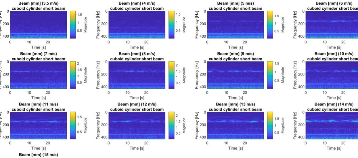
Fig. 12. Continuous wavelet transform of the beam deflection with cylinder-cuboid during excitation by air at velocities from 3.5 to 15 [m/s]
Tab. 5.
Energy harvested output of the three bluff body configurations
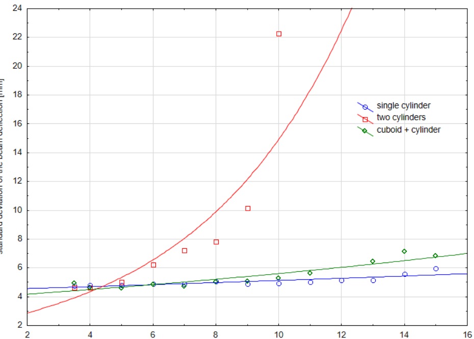
Fig. 13. The standard deviation of the beam deflection [mm] for three tested systems depending on the air velocity with exponential fits
The open‑circuit piezoelectric voltage is related to strain in the beam. However, the measured voltage after the EH module is conditioned and therefore cannot be treated as linearly proportional to deflection. The voltage from the PZT changes polarity and is characterized by high variability, particularly the occurrence of high-voltage peaks (over 10 V, even up to 30 V), which can damage the powered receivers. For this reason, a commercially available EH301A circuit element was used to receive the voltage signal from the PZT generator and charge the capacitor. This element filters and adapts the signal to power low-voltage receivers. The output of EH301A is inherently unipolar (only positive) cause the module stores energy on an internal capacitor referenced to ground and uses MOSFET threshold switches to deliver it. There is no inverter stage to generate negative voltage. It’s designed to power low-power CMOS circuits and sensors that only need +3 up to +5V. The input voltage increases from 0 V, and when it exceeds a high value (VH), the output is activated, maintaining a voltage no higher than VH. During this time, the EH301A circuit continues to accumulate energy from an external source. If the input voltage drops below VL, the output power is turned off. Operating in this manner, the EH301A circuit generates a supply voltage in the range from VL to VH, with periodic interruptions as the input voltage drops. Therefore, it can be assumed that powering low-voltage loads is only possible using a capacitor (using a supercapacitor is recommended). This signal was recorded during the experiment to assess the system's ability to charge capacitors and power low-voltage loads.
EXPERIMENTAL RESULTS
The experiments were conducted in the open-way wind tunnel by varying the air speed in the range of 3.5 to 15 m/s. The given wind tunnel setup is presented in Figure 1.
Figures 5, 6, and 7 show the 30-second raw beam deflection signal recordings from three systems with different bluff body shapes. In the case of the two-cylinders setup, increasing the velocity above 9 m/s resulted in excessive deflections, posing a risk of damaging the test stand components. The zero value is at the center position of the beam.
It is observed in Figures 5, 6, and 7 that the voltage response exhibits a certain degree of asymmetry between positive and negative peaks, which becomes more prominent at wind speeds exceeding 9 m/s. This phenomenon can be attributed to the static deflection of the cantilever beam caused by the increasing mean aerodynamic drag force at higher velocities. This means deflection shifts the equilibrium position of the piezoelectric transducer. Additionally, the mechanical assembly, where the bluff body is clamped to one side of the beam's tip, introduces a slight mass and stiffness eccentricity, further contributing to the asymmetric voltage distribution during high-amplitude oscillations. Also, this phenomenon is caused by characteristics of the EH301A electronic circuit. This circuit generates a unipolar output signal (positive only), which additionally highlights the asymmetry in the voltage recording (see details in Section 4).
During the experiments, an increase in the variability of the beam deflection was observed with increasing air velocity in the tunnel. In the case of the single-cylinder system, a local increase occurred during stimulation with air at 9 m/s, followed by a decrease in the spread (see Fig. 8). These are local increases in the maximum beam deflections in both directions. The Reynolds number for this system ranges from 8.1×10³ (for air velocity v = 3.5 m/s) to 3.5×10⁴ (v = 15 m/s, diameter d = 34.8 mm, kinematic viscosity of air at 20°C is 1.5×10⁻⁵ m2/s). This range supports periodic vortex shedding and vortex-induced excitation. Therefore, the observed non-monotonic changes in the deflection range can be attributed to VIV lock-in and wake–structure interaction rather than purely laminar near-wall flow. In the case of the two‑cylinder system, the deflection increases gradually and nearly linearly up 10 m/s, reaching a maximum of 11 mm. This is due to strong vortex‑induced vibration (VIV) lock‑in and the onset of low‑frequency galloping, leading to high energy output but also structural instability, which limited testing to ≤10 m/s. In contrast, the cylinder–cuboid configuration exhibits a much sharper and nonlinear increase in deflection with wind speed, exceeding 9 mm at the highest airspeed 15 m/s. The hybrid geometry suppresses unstable low‑frequency modes. The sharp edges of the cuboid generate a less coherent vortex street, reducing periodic lift fluctuations and thereby decreasing the dynamic forcing on the beam.
The normalized standard deviation analyses of beam deflections are presented in Fig. 9. The statistical variability for the given setups emphasises that there is a +40% growth between 3.5 and 15 m/s in the case of the single-cylinder. The setup with the two-cylinders achieves 89% growth (relative to the single-cylinder case). At the same time, the cylinder-cuboid configuration achieved ~25% lower slope than the single-cylinder structure.
The appearance of a low-frequency component characterized the deflections of the two-cylinder system with increasing air velocity, but due to excessive beam deflections, further experiments were discontinued (ranges 3.5–10 [m/s] in Fig. 8 and Fig. 9).
However, in the case of the system with a bluff body consisting of a cylinder-cuboid, the variability of the deflections expressed as standard deviation increased at a lower rate than in the case of the single-cylinder system.
Continuous wavelet transform (CWT) graphs of beam vibrations are presented in figures organized by air (wind) velocity and divided into groups based on the system configuration. The wavelet graphs show an increase in the activity of the flexible beam deflections.
The graphs obtained during wavelet analysis of the beam deflections show the frequency ranges in which the tested vibration systems were activated during the 30-second recordings. As air velocity increased, activity in the lower frequency range was amplified. The vibration analysis graphs for the single-cylinder system (Fig. 10) show short-term amplifications of vibration activity around 250 Hz (short periods of amplitude amplification separated by lower values). At air velocities of 6 and 7 m/s, additional periodically varying vibration components appear, with frequencies ranging from 250 to 320 Hz. The system consisting of two-cylinders is characterized by longer periods of amplitude increases than in the previous case, lasting several seconds (components at values of 140 and 210 [Hz]. There is also a clear enhancement of activity in the low-frequency range below 50 Hz, and their periods of activity are long-lasting (bands lasting over a dozen seconds). In the case of the system with the cylinder-cuboid, there was an enhancement of activity in the lower frequency range (around 150 Hz). The increase in activity in the form of a figure appears to be proportional, and the experiment can operate at higher air speeds, exceeding 15 m/s.
The wavelet transformations in the case of two-cylinders and the cylinder-cuboid setup are presented in Fig. 11 and Fig. 12, respectively. In particular, in the case of two cylinders setup (Fig. 11), we have observed the beam deflection amplitude increase with frequency, achieving the maximum deflections (resonances) at 130 Hz and 220Hz. This situation is recorded for input air velocity increased from 3,5 m/s to 9 m/s. These persistent low-frequency modes suggest strong nonlinear wake–structure coupling, with vortex synchronization leading to large deflections. For the higher air velocities, the beam deflections exceeded the boundary of the test setup, limiting safe operation, as confirmed by the rapid increase in beam displacement noted in earlier measurements. This indicates that, although the two-cylinder geometry enhances energy harvesting potential through strong VIV lock-in, it does so at the expense of structural stability.
The beam deflection spectrum response with cylinder–cuboid configuration (see Fig. 12) presents a contrasting behavior. The wavelet analysis shows a more distributed frequency response, with dominant activity around 150 Hz and proportional amplification across the velocity range up to 15 m/s. Unlike the two-cylinder system, no abrupt transition to unstable low-frequency modes was detected. Instead, the cylinder-cuboid hybrid exhibited smoother growth of vibration energy and maintained stable dynamic behavior across the full wind-speed range. This points to the hybrid’s ability to sustain broadband energy harvesting without risking uncontrolled oscillations.
Table 5 quantifies the electrical output performance of the three bluff body configurations across the tested range of air velocities. To move beyond raw voltage and provide a more rigorous comparison of energy harvesting efficacy, the measured signals have been processed into two key engineering metrics: RMS Voltage (VRMS) and average power Pavg=VRMS2 / R, where R=1 MΩ represents the usable electrical power delivered to a matched load.
The table underscores the fundamental trade-off between peak performance and operational stability. The two-cylinder configuration achieves a superior power output of 144 µW at 9 m/s, but its operation beyond this velocity was precluded by excessive, structurally unsafe deflections. In contrast, the cylinder-cuboid hybrid demonstrates robust and sustainable power generation, increasing steadily to 56.3 µW at 15 m/s without exhibiting instability, confirming its suitability for broadband, real-world applications.
To enable a fair comparison of bluff body configurations with different masses and volumes, Table 5 also includes power density per unit mass (Pavg_mass) and per unit volume (Pavg_vol). These normalized metrics account for differences in size and mass, allowing a more reliable assessment of the energy efficiency of each geometry. The comparison reveals that while the single-cylinder has the lowest mass, it achieves the highest power density of 3.06 µW/g. Interestingly, the cylinder-cuboid configuration, despite its higher mass and complex geometry, shows a decrease in performance at high wind speeds. This suggests that the cuboid section introduces aerodynamic damping or alters the vortex shedding frequency in a way that disrupts the synchronization (lock-in) between the fluid flow and the structural resonance. These results emphasize that increasing the mass or complexity of the bluff body does not linearly correlate with harvested energy, as the aerodynamic shape optimization remains the dominant factor for VIV efficiency. The two-cylinder system, despite its length, benefits from a more complex wake interaction that sustains oscillations.
The deflection variability for given setups is presented in Fig. 13. The standard deviation of beam deflections followed exponential trends similar to voltage outputs. In the case of a single-cylinder setup, the variability grew steadily from ~4.5 mm (3.5 m/s) to ~6 mm (15 m/s), confirming a nearly linear-to-exponential transition (R² = 0.94). The setup with two-cylinders has variability surged sharply, reaching over 22 mm at 10 m/s before the experiment was stopped. Regression showed strong exponential growth (R² = 0.96). In the last configuration of cylinder-cuboid, the variability remained the lowest, increasing from ~5 mm to ~7 mm across the whole range, with R² = 0.93. Analysis confirms that variability in beam deflection correlates strongly with energy harvesting potential: higher variability (two-cylinders case) results in larger voltage peaks but compromises stability, whereas lower variability (cylinder-cuboid setup) balances efficiency with robustness.
The results confirm that bluff body geometry plays a decisive role in the balance between harvested energy and structural safety. While the configuration with two-cylinders maximizes output, it is not viable for sustained operation at higher speeds due to excessive oscillations. Conversely, the cylinder-cuboid hybrid demonstrates the most stable performance, suggesting its suitability for broadband, variable-speed environments such as outdoor sensor nodes. Linking frequency bands from CWT to Strouhal number predictions confirms vortex shedding in the subcritical Reynolds regime in the single-cylinder case and wake coupling in the case with the two-cylinders. These aerodynamic mechanisms explain the differences in energy harvesting efficiency.
CONCLUSIONS
In this paper, a wind-induced vibration energy harvesting (WIVEH) system consisting of a flexible beam with three bluff-body configurations, including single-cylinder, double cylinders, and cylinder-cuboid, connected with the piezoelectric transducers (PZT) is presented. The paper provides a robust experimental investigation into the role of bluff body geometry on Vortex-Induced Vibration (VIV) and galloping for piezoelectric energy harvesting. The key findings—the high-yet-unstable performance of the two-cylinder configuration versus the robust, broadband efficiency of the cylinder-cuboid hybrid—point directly to several advanced research avenues. The main paper outcomes are as follows:
• The cylinder-cuboid hybrid bluff body demonstrated the most stable dynamic response, with 15% lower variability growth compared to the single-cylinder, and potential for operation above 15 m/s.
• The system with two-cylinders achieved the highest energy conversion efficiency (up to 144 µW) but suffered from uncontrolled oscillations, making it suitable only for low-speed applications (e.g., HVAC systems).
• The single-cylinder system exhibited predictable and moderate performance, with exponential voltage growth and acceptable power harvesting (up to ~110 µW) at the maximum airspeed of 15 m/s, but with efficiency limitations.
• Continuous wavelet analysis revealed distinct frequency bands linked to vortex-induced vibration and galloping, confirming the role of nonlinear aerodynamic interactions in energy harvesting efficiency.
• Practical applicability: The harvested energy is sufficient to intermittently power low-voltage IoT devices, wireless sensors, or small LEDs, depending on the bluff body configuration.
The future work will focus on research directed along three interconnected thrusts: high-fidelity diagnostics, advanced geometry optimization, and system-level integration. Firstly, to unravel the nonlinear fluid-structure interactions responsible for the observed stability of the cylinder-cuboid hybrid, time-resolved Particle Image Velocimetry (PIV) will be coupled with the simultaneous measurement of beam strain and voltage output. This will directly correlate the modified vortex shedding dynamics, wake patterns, and pressure distribution with the temporal electrical response, quantitatively explaining the suppression of destructive low-frequency modes. Secondly, the promising concept of geometric hybridization will be expanded through a parametric study of the cuboid's aspect ratio, its longitudinal positioning along the cylinder. This optimization will be guided by a co-simulation framework combining Computational Fluid Dynamics (CFD) and transient structural-electrical models to predict the lock-in regions and galloping onset for complex shapes. Finally, to transition from laboratory proof-of-concept to field-deployable technology, the optimized harvester will be integrated with an adaptive power management circuit featuring maximum power point tracking (MPPT). This system will be subjected to long-term testing under realistic, broadband turbulent flow conditions to validate its efficacy in powering representative IoT sensor nodes, thereby closing the loop between fundamental FSI discovery and practical energy autonomy.