INTRODUCTION
The production program of the company in Považská Bystrica includes the production of large bearing rotations with diameters of 3000 mm and spur gears with a gear module 22, but also the production of special gearboxes with worm gears, which are called Integrated Gears (IP). Until now, IPs have been produced exclusively with worm gear, which has a cylindrical worm and a cylindrical worm wheel.
Currently, the market requirement is to supply gearboxes with a cylindrical worm and a globoid gear worm gear. The production of a globoid gear worm wheel represents the development, verification, and introduction of rolling milling of gears in a tangential way.
They approach this activity with respect as it is about mastering the whole complex of tasks, such as selecting a semi-finished product, designing chip machining, designing heat treatment, measuring dimensions and shapes in the machining process and during the final inspection, final assembly of the gearbox, and finally testing the gearbox on test equipment under load.
METHODS
For large worm angles or precise gears, tangential rolling milling is used to produce gears on the worm wheel. The method is suitable for screw inclination angles greater than 8°. This prevents adverse tooth flank cuts that occur with the radial milling method.
In the tangential method of hobbing milling, the hobbing cutter is set exactly to the axial plane of the worm wheel R to the prescribed distance A2,n = A1.2, which also represents the axial distance between the auger axis and the auger wheel axis. The machined wheel rotates at speed n2, the tool rotates at speed nn and simultaneously moves in the direction of the tool axis by tangential feed stg. All movements are tied to each other. At the beginning of machining, the cutter touches the wheel rim, and the final position of the cutter occurs when chips stop forming, the tool is no longer in engagement, and the gearing is finished.
EXPERIMENT
Selection of the representative, worm wheel with module 5
The production process is processed for individual workplaces in the company in Považská Bystrica. A brief schematic procedure is given in the following section. The production is based on a semifinished forged ring with dimensions Ø332±3/220±3x79±1. The material used to produce the ring is steel, marked 42CrMo4 V.
The subject of research is a bearing ring type 1372-H15/1, the specific machining of which is dealt with in the company in Považská Bystrica. In this company, authors were present at the specific production of rings with the designation 1372-H15/1.
Technology of chip machining of worm wheel production
The production process is processed for individuals. The production is based on a semifinished forged ring with dimensions Ø 332 ± 3 / 220 ± 3 x 79 ± 1. The material used to produce the ring is steel, which is marked 42CrMo4 V.
The worm wheel manufacturing process consists of 17 operations:
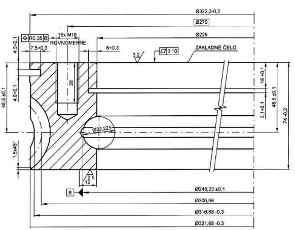
Operation 1 – OKUMA CNC machine: turn the base face clean to *78 - 1; surface area to *324 ± 0.2; hole for *PR.229 ± 0.2 to a depth of 39 ± 0.5; chamfer edges 1x45°. Check: radial run-out max. 0.15 mm; axial run-out max. 0.1 mm.
Operation 2 – OKUMA CNC machine: turn the other face to *78 - 0.5; installation on the surface *PR.321.8 ± 0.1 to depth *62.5 ± 0.2 with a run of 45°; relief R18.9 to *PR.316.8 ± 0.1 distant 49 ± 0.1 from the base face; rest of the hole on *Av. 229 ± 0.2; rough orbit; turn the R11,13 orbit with an offset of 0.293 to *PR.247.55 ± 0.1 with the addition after heat treatment, maintain the dimension *49 ± 0,1 from the base face; (measured through bullets PR.21.425); R4 in orbit to a depth of 11 + 0.2 from PR.229; chamfer the edges of R2 in the orbit; chamfer edges 1x45° on the forehead; orbit profile according to company standard 3002 - version 450. Check: radial runout max. 0.1 mm; axial runout 0.1 mm.
Operation 3 – FO10 roll milling machine: roll the gears for the main time of 140.3 min; measure through the balls PR.8 before quenching = *315.7 - 0.1; maintain a distance of *49 ± 0.1 from the base front.
Operation 4 – manually: gear finish; chamfer edges 1x45°.
Operation 5 – SAET-1 quenching equipment: teeth induction perimeter hardening.
Operation 6 – inspection of the Tiede 650 crack device: check according to the instructions TgP 02-TS-3/96.
Operation 7 – tempering furnace KZO 117: temper in an electric furnace (180 mins).
Operation 8 – HWG quenching furnace: inductively harden the orbit to a depth min. 2.8 mm on HRc =59±4.
Operation 9 – inspection of the Tiede 650 crack and hardness equipment: check according to the instructions TgP 02-TS-3/96.
Operation 10 – hydraulic press: Check: radial runout PR.321.68 *max. 0.075 mm; ovality PR.321.68 *max. 0.15mm; (measure at the other front) axial runout *max. 0.1 mm; straighten as needed.
Operation 11 – OKUMA CNC machine: turn the other face to *74.5 - 0.2; (sealing rate from PR. 229 in a width of 12 mm machining Ra=2.5); chamfer a 1x45° edge on a surface; chamfer edge 1x45° in the hole.
Operation 12 – OKUMA CNC machine: indicate from PR. 321.68; turn the base face to *74 - 0.2; surface area at *PR. 322.3 - 0.2; groove 3.1 + 0.1 to a depth of 6 + 0.3 *18 + 0.1 from the base face; a groove of 4.6 + 0.1 at a distance of 4.5 + 0.1 from the base face; chamfer edges 0.5x45° in grooves; chamfer edges 1x45° on the forehead.
Operation 13 – AXA6-CNC DBZ drill: drill 16 PR.14 holes on the pitch circle *PR.270 to a depth of *36 mm; chamfer edges 1.3x45°; cut thread *M16 in clamping holes to a depth of *28 mm.
Operation 14 – OKUMA CNC machine: indicate from gearing, gear runout max. 0.1 mm; turn the R11, 53 orbit with an offset of 0.293 to *PR. 248.23 ± 0.1 (bullet measurement PR. 22.225); keep the center of the orbit *48.5 ± 0.1 from the base front; orbit profile according to company standard 3002; version 45°; axial and radial raceway runout max. 0.03 mm.
Operation 15 – inspection of the Tiede 650 crack and hardness device: incarnate gearing 100%; orbit randomly.
Operation 16 – manually: check according to the instruction letter O.K.
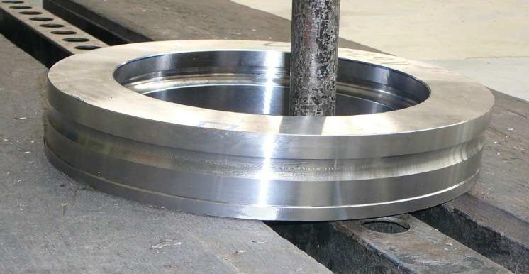
Operation 17 – manually: incarnate gearing 100 %; orbit randomly; blow out with compressed air; preserve in intermediate storage as needed; Ring after heat treatment is in Fig. 1.
In the technological procedure, authors present specific company standards that are used in the production of the company in Považská Bystrica TgP02-TS-3/96 – deal with the hardness of the ring and surface control for cracks PN 3002 and deal with the detailed geometry of the orbit. Tiede 650 is the injection of induction fluid on the surface of the ring.
Manually– discusses the inspection of the instruction sheet with the dimensions of the induction scale teeth [1]. After the hardening is completed, the ring is inspected with the naked eye or a microscope, where it is checked for cracks according to the TgP 02-TS-3/96 guideline and then transported to the KZO 117 electric furnace, where tempering takes place, which lasts 180 mins. Another operation is induction hardening of the raceway in a furnace marked HWG. After the last operation in the hardening plant, we check the ring according to the instructions, check the surface for cracks or the hardness of the ring. This is followed by pressing on a hydraulic press and further turning according to the technology sheet. The next operation after turning is to drill holes along the pitch circle on the AXA6-CNC DBZ drill, chamfer the edges and create an M16 thread in the clamping holes. Only finishing operations, such as final turning on OKUMA CNC. At the end, the orbit is checked, an inductive liquid is injected onto the surface of the ring so that dents can be detected, manual inspection is done, and the product is with compressed air as needed and either exported or preserved in the intermediate warehouse. The machine follows OKUMA CNC. The orbit was checked at the end, and an inductive liquid was injected onto the surface of the ring so that dents could be detected; manual inspection, and the product was with compressed air as needed and either exported or preserved in the intermediate warehouse.
Production of globoid gears
Globoid gears, under company conditions, can be produced on hobbing milling cutters marked FO-10, FO-16, and LIEBHER. The company uses the FO-10 milling cutter for milling, on which globoid gear milling tests were carried out. A turning semi-finished product is used for milling, the shape of which is shown in Fig. 2.
Description of workpiece clamping
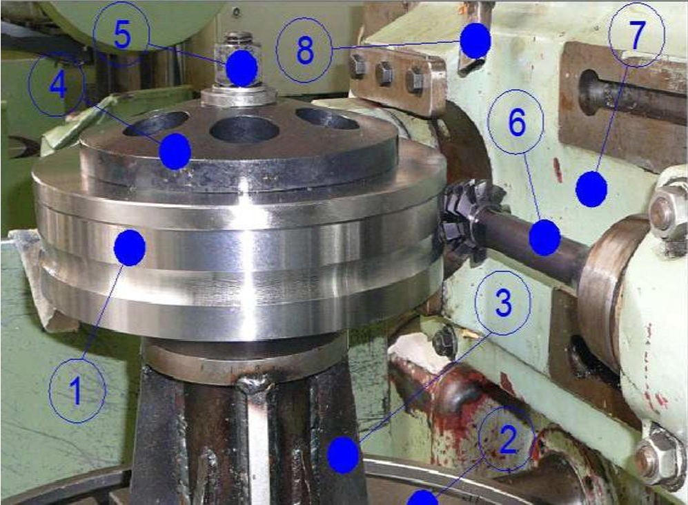
The clamping method is shown in Fig. 3. The semi-finished product – the ring (1) is clamped in a special jig (3), which is placed on a rotary table (2), which is equipped with clamping grooves through which the grooves are clamped. A clamping fixture is set on the turntable, which is attached to the table with 4 screws. The stand comprises several parts; the welded structure is reinforced for stiffness. A semi-finished product – a ring – is placed frontally on the fixture, where the clamping flange (4) is placed. The clamping flange is circular and clamps the semi-finished product with the clamping jig. The clamping force is applied through the clamping nut (5). When clamping, the ring is adjusted – centered on the center of the table, and the radial runout of its surface is checked. The permissible radial discharge is 0.003 mm. Clamp the tool – the hobbing cutter (6) – into the spindle of the tangential slide (7). The tool is set to the home position. The tangential axis of the tool must be set so that the first tooth of the tool is exactly before the bite. At the same time, the position of the tool is set to the axial plane of the worm wheel R. The machine starts the tool, and the semi-finished product rotates with an interlocking motion, with the tool performing a tangential feed. At a certain position, the tool begins to form a gear shape, as shown in Fig. 4. At this stage, the operator checks the correct setting for the number of teeth. If the correct setting is achieved, the machining occurs until the final production. Coolant is supplied between the tool and the workpiece through a coolant (8) to improve cutting conditions.
Tool Clamping Description
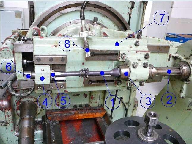
The tool (1) is clamped on the tangential support (7), the clamping is carried out using the carrier (3), which is part of the headstock (2). The other end of the tool is clamped in the support bearing. The tool is tightly tightened by the nut (6) into the sliding bronze case (5). The bronze bushing rotates in the support bearing. The tangential shaft gives the tool an axial tangential motion and, at the same time, receives torque from the headstock as the workpiece rotates with the workpiece of the rolling body. To create optimal cutting conditions, the tangential slide is equipped with a cooling nozzle (8) for cooling and lubrication during the cutting process. The tool clamping method is shown in Fig. 4.
Fig. 4 shows the general view of the hobbing cutter, a machine of type FO-10, which produces gears for serial production. Its parameters are shown in Table 1.
Schematic design of a tool a hobbing machine
Machining of globoid gearing in the conditions is carried out by milling using the tangential rolling method.
Milling using the tangential rolling method
The tool is a tapered hobbing cutter, shown in Fig. 5. The cutter is made of high-performance high-speed steel. The cutter consists of a cutting part (1), which consists of teeth that are ground. The left part of the driver is formed by a Morse cone (3) and a grip face (4). The right side of the tool consists of a support cylindrical part (2) terminated with a thread.
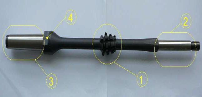
Fig. 5. Tool - tapered hobbing cutter (1 – cutting part; 2 – supporting cylindrical shank; 3 – morse cone; 4 – drift pads)
Tab. 1.
Main dimensions and technical data for the hobbing machine, machine type FO-10
The manufacturer proposes that the tool face can be resharpened 17 times after its wear, and when resharpening, the value of the largest diameter of the last calibration tooth is checked on the cutter.
The manufacturer provides a protocol for the tool, which indicates exactly the nominal values to which the tool is to be sharpened. The tool is resharpened under the conditions of the company in Povazska Bystrica on a KAPP sharpening grinder.
The shape of the burring cutter is a screw. The conical shape of the tool has the advantage that the tool creates gearing gradually, during milling, the first teeth enter the engagement first – the roughing teeth, which gradually form tooth by tooth in the shape of the tooth profile through the conical shape of the tool. In the initial phase of machining, the first teeth work as roughing, gradually as the cutter moves in a tangential direction while rotating the tool and the wheels remove additional material, creating the final shape of the tooth. This conical shape tool has the advantage that the tool removes the material gradually during machining, making the machining smooth without large impacts. The last calibration teeth will produce the profile of the globoid gear teeth with good precision and high-quality surface treatment.
The production of globoid gears in a tangential way is a very precise method, but the condition is the production of a precise tool. Making a tool with a hobbing milling machine is a demanding and lengthy process, but the basis is a precise design calculation [2] of the milling cutter and preparing a production drawing according to the customer's requirements. During the design, the amount of material to be removed must be determined – calculate the amount of material to be removed so that the individual teeth of the tool take approximately equal amount of material.
The tool geometry (face angle, back angle and side cutting edge angles) is designed in such a way that there are no unnecessary large friction losses during machining and that tooth wear is as low as possible. Cutting tool marks that remain on the sides of the teeth increase tooth wear when the wheels are rolled away, impairing transmission efficiency and increasing noise. To produce high-precision gearing, finishing methods of gear production are used to improve the quality of the tooth surface, maintain the exact involute shape of the tooth profile and remove sharp edges. In general, finishing methods to produce gears include, in particular: chatter, grinding and lapping.
Description of the sharpening of the tool
The description is shown in Fig. 6. The tool – the hobbing cutter (1) is clamped between the clamping tips (2), which are mounted and fixed on the grinding table. On the left side of the tool, the hobbing cutter is firmly connected to the headstock (5) by the guide pads (4). Clamping on the left side of the tool. The machine will be set with prescribed values such as the angle of the tool face, the angle of inclination of the tool grooves (3), and the exact division into eight grooves designed by the tool. When we have a properly fitted and attached tool – a rolling mill, there is a slow but precise grinding of the tool, using a grinding wheel (6).
For sharpening tools in the company in Považská Bystrica, a grinding wheel from TYROLIT is used, the values of which are shown in Table 2. When sharpening, the values listed in Table 3 are checked on the tool k, namely the angle of the tooth face, the machining of the face surface, and the inspection of the sharpened area for burns. Grinding is carried out on a FO-10 type machine.
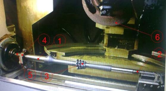
Fig. 6. Grinding process of the tool – hobbing cutter on the machine (1 – tool – hobbing cutter; 2 – clamping tips; 3 – tool groove; 4 – drift pads; 5 – headstock; 6 – grinding wheel)
Tab. 2.
Parameters of the grinding wheel from TYROLIT
| Dimension [mm] | Quality | Rotation speed [ot.min-1] |
|---|---|---|
| 300 x 29 x 51 | 98RA99/BA54H10VC40 | 2540 |
Tab. 3.
Tool values given by the manufacturer for tool grinding
RESULTS AND DISCUSSION
The results of globoid gear pitch circle measurement and globoid gear impression measurement results are presented in this chapter.
Schematic design of a tool a hobbing machine
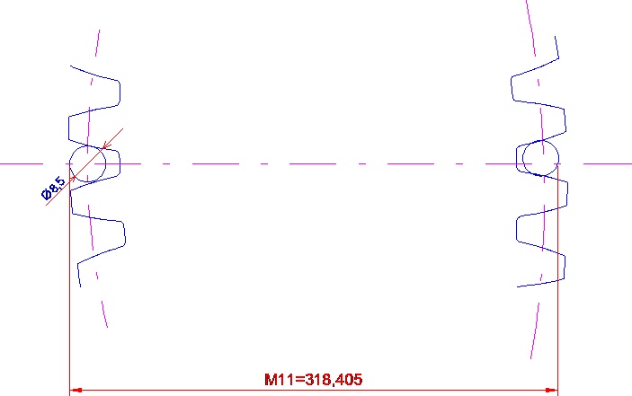
The measurement diagram through the balls is shown in Fig. 7, and the design parameters proposed by the designer are given in the Gear Design Rulebook, Table 4, and it is a measure of 318.405 using balls of size 8.5.
Tab. 4.
Gear design code
When making the ring on the FO-10 machine, the measurement through the balls is checked, which is specified in the design code for gearing 9E-1B22-0226-1372-H15 (Table 5 – in the Annex), and the measure 318.405 is prescribed, and it is measured through the balls of 8.5. During production, this measure is checked on the finished gear (the final shape of the gear). The measurement through the balls in the gear statement must be added, and the measure must be set on the gauge according to the design regulation prescribed by the designer.
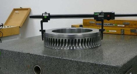
The measuring tape measured through the balls is shown in Fig. 8 and is a specially modified gauge. A caliper (1) with a digital display (5) is used on the gauge, attachments (2) are screwed onto the gauge, and there are rests (3) on the gauge. At the end of the attachments, the measuring balls are screwed on (4). The armrests are set to the exact value of c, which represents the distance of the center of the globoid from the base forehead.
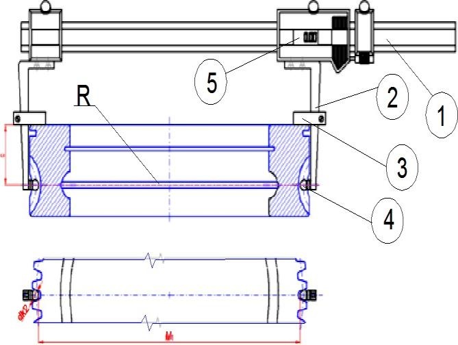
Fig. 8. Measurement of the pitch circle using balls (1 – caliper; 2 – attachment; 3 – head restraint; 4 – measuring ball 8.5; 5 – digital display; M – dimension through the balls “dk1”; dk1 – diameter of the measuring ball; c – distance of the axial plane; R – radial plane)
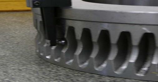
Fig. 9 shows the view when measuring the pitch circle of a threaded gear. Fig. 10 shows the detailed contact of the measuring ball with the sides of the teeth on the pitch circle.
Measurement of globoid teeth per impression
The imprint measurement is performed on a machine that works on the principle of rolling the screw with the wheel. In the case of an unsatisfactory shape, the machine setting is corrected in the production of globoid gearing (the tool is moved up, down, etc.). So, we can introduce production. In practice, we first produce the first prototypes, on which we check the setting and correct the setting for the next piece. Fig. 11 shows the methodology for evaluating the contact of the worm wheel tooth surface with the worm wheel, called the imprint check.
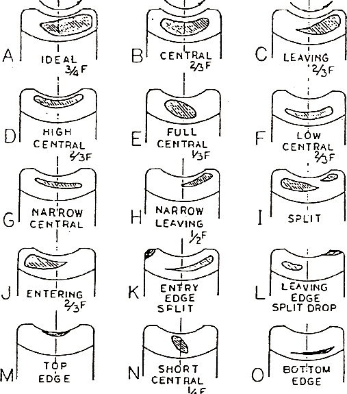
Ideal contact is represented by Fig. 11 A. The samples in Fig. 12 B, C, D, E, and F are cases of acceptable impressions. The samples in Fig. 11 G, H, I are partially acceptable. Imprints on Fig. 11 J, K, L, M, N, and O are unacceptable. Acceptability or inadmissibility is evaluated according to the use of the gear (accept – different requirements for machine tools that are very precise and different requirements for less precise gears).
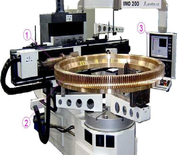
Fig. 12 shows a special machine for detecting defects using an imprint using paint that is painted on the surface of the wheel – gear (2) and with the help of a worm (1), which rotates evenly and enters the individual teeth, and creates a paint imprint on them. The evaluation is done on a computer (1).
For investment reasons, the company in Považská Bystrica is preparing to manufacture a replacement gauge, which will be able to check the imprint when gears roll. The gauge is designed to be fixed to the transverse support of the lathe and a screw is fixed between the tips on the lathe tailstock and in the lathe spindle. A worm wheel is inserted and fixed in the gauge. The auger wheel and auger are adjusted to the bite position. A slow rotation of the spindle will start, which will carry the auger, and it will simultaneously engage with the auger wheel. The sides of the worm wheel teeth are painted with a control paint (ink spray). When moving together, an impression will be created on the teeth of the worm wheel.
Principle of measuring the position of the globoid gear in relation to the clamping face of the assembled bearing
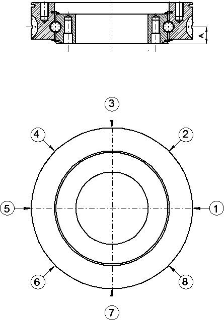
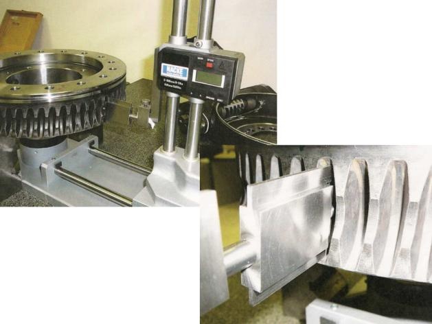
The aileron is set to the exact value of the prescribed distance of the globoid from the mounting face (A) and evaluated on the digital display of the measuring instrument. The aileron is inserted into the individual tooth gaps, while its sharp edges must touch the cylindrical surface both above and below the tooth gap, as shown in Fig. 13. The value on the display shows the deviation from the nominal prescribed value. During the measurements of the bearing type 9E-1B22-0226-1372-H15 (Fig. 14), the values were measured in Table 6 (in the Annex).
From the measured values, it was found that they are 0.2 mm deviations from the required size. However, since the case size is 34.75 and the deviation is 0.2 mm, the measurement is correct because the value of 0.2 is still within tolerance according to the design regulation.
CONCLUSIONS
The conclusions are divided into two perspectives, namely the economic benefits and the evaluation of the obtained results for practice.
Economic benefit
Until now, worm gearboxes in the company in Považská Bystrica have only been produced with an inclined gear on a worm wheel. As there has been so far from the production of a smaller number of gearboxes with globoid gears, their production has been ensured in cooperation with other manufacturers. At present, customer requirements for globoid gear transmissions are constantly growing, so the company has decided to introduce the technology of production of globoid gears by rolling milling in a tangential way in its premises. Such a decision will bring financial savings and improve the operability of the production process. In the next part of the work, these savings are calculated.
When analyzing the cost of manufacturing globoid gearing on the outer ring, part number 1372-H15/1 was proceeded from the total labor intensity of its milling in a tangential manner and from the time rate to the workplace where the operation is performed.
The cost of gear milling (N) is calculated according to the relation:

where
N is milling costs [Eur]
tc is the norm of time [min]
Nmin are costs per 1 min of work, the so-called workplace rate [Eur/min]
In calculating the cost N, the time standard tc is the sum of the main and secondary time. The prime time is the time during which the tool is working to remove material. Secondary time is the time needed to clamp, align, center, measure a part, but it also includes a proportional part of the time required to line up the machine (clamping the fixture, clamping the tool, setting the parameters of the machine tool, etc.). The Nmin value expresses the sum of variable and fixed costs for a specific gear milling workplace by rolling in a tangential manner and is expressed as a financial amount per 1 min. Variable costs represent the costs of wages, energy consumed by the machine tool, and the purchase and sharpening of the tool. Fixed costs consist of the costs of depreciation of production equipment, work protective equipment for operators, other energy such as heating, removal of production waste, and testing laboratory services. The cost of making the worm gear for the bearing 9E-1B22-0226-1372-H15, which was produced in cooperation, is 84 Euros.
By producing this globoid gear on its own premises, the company in Považská Bystrica will save a financial amount of 42.9 Euros, which represents the difference between the costs of cooperation of 84 Euros and its own costs of 41.1 Euros.
Evaluation of the experimental part for practice
The aim of this research work was to design globoid gearing on the outer ring of the bearing 9E-1B22-0226-1372-H15 according to the technological procedure. The produced globoid wheels were measured by two methods. During the first measurement, the pitch circle on the globoid gear was measured, which was made according to the technological procedure. On a globoid toothing, use a digital caliper that rests on the attachments on which balls of a diameter of 8.5 mm are attached. During this measurement, the measured values were compared with the construction regulation that was proposed by the design department according to the customer's requirements and production capabilities.
With the first measurement, globoid gearing was already found to have the required large pitch circle. For the accuracy of the measurement, the measurement was repeated on the other two manufactured globoid gears, which were also manufactured according to the same technological procedure as the first measured globoid gear. Even with these two measurements, it was found that the globoid gearing has the prescribed measurement through the balls given in the design regulation.
The prescribed value is M11 318.41 mm. The ball measurement method was proposed as part of the development of globoid gear machining. For these purposes, a special meter was purchased. The measurement results have been verified by the design regulation; the measurement is reliable and sufficient.
The second measurement was carried out on a measuring device designed in the technical and construction department. In this measurement, the correct distance between the center of the globoid gear of the worm gear and the clamping face of the turn was determined. The measurement results are verified according to the construction regulations.
The measurements were successful, and this was confirmed, according to the previously prescribed building regulations. Attached are photos of the production and measurement of globoid gearing.
This research work was supported by the Cultural and Educational Grant Agency of the Slovak Republic (KEGA), project No. KEGA 001TnUAD-4/2025.
Appendix 1
Tab. 5.
Dimensions ready (after hardening)
Appendix 2
Tab. 6.
Measurement results of globoid gearing against the clamping face of the assembled bearing