INTRODUCTION
Mixing is an operation frequently used in several industrial sectors such as pharmaceutical production, agri-food, cosmetics, chemicals and petrochemicals, metallurgical industry, production and processing of dairy products, and production and treatment of water. Almost all processes and equipment require some type of mixing or agitation, and the flow pattern depends on the type of agitator and the speed of agitation [1]. Most previous studies have focused on conventional vertical baffles for controlling swirling flow in stirred tanks. In contrast, limited attention has been given to non-conventional geometries such as square and triangular baffles. These shapes introduce different flow separation mechanisms and vortex structures compared to traditional designs. The present study addresses this gap by providing a comparative analysis of vertical, square, and triangular baffles, emphasizing the specific influence of square and triangular.
The operations carried out in tank reactors with mechanical stirring may vary depending on the vessel chosen, the impeller design, and the number and type of baffles. If a stirred vessel filled with low viscosity fluids does not have baffles, the rotating impeller will cause the liquid to move tangentially [2]. The impact of baffles on the power number of a maxblend turbine was studied by Iranshahi et al in 2007 [3]. The authors examined the power consumption of a baffled tank and compared it to one without baffles. During the comparison, they observed that the power consumption of the agitated tank was higher than that of the other tank.
The majority of agitation and mixing operations are performed using an impeller that rotates around a shaft placed in a tank, typically cylindrical in shape. In stirred tanks, the induced hydrodynamics are mostly dependent on impeller design and the interaction of flow with tank internals [4-7]. Several studies have been conducted on hydrodynamics and mixing in vessels with varying geometrical configurations agitated by different types and design of impeller [8-15].
During recent years, studies have focused on the energy consumption of impeller-vessel systems with different geometries and researchers' attempts to reduce this consumption. Among other mixing characteristics, the power number (Np) is an important parameter of the stirred tank, which is generally used to validate computational fluid dynamics (CFD) simulations [16-17].
When the agitator rotates, a strong vortex is formed as a result of the centrifugal force, which can damage the components of the agitator. To prevent this problem, barriers are installed, also known as anti-blades, which are vertical elements fixed to the level of the tank wall. They are used to prevent vortex formation and are necessary to achieve an effective mixture in the state of turbulent flow.
The main objective of baffle inserts in stirred tanks is to prevent swirling flows, reduce viscous dissipation caused by the impeller, create and promote stable power requirements, and thus enhance mixing [18].
Some studies have been conducted on the effect of baffle design, including those by Lu et al. (1997), Yeum et al. (2019), and Shen et al. (2020) [19-21]. Through experimental studies, the results show that the power consumption of agitated vessels equipped with beveled blade turbines and short flat baffles is within the range of the measurements taken, and that the power number (Ne) depends on the length (L) of the baffle and the angle (β) of the blade inclination of the turbine [22].
The investigation examines the effect of vessel configuration and agitation rates on flow structure and power consumption. Three types of vessels were used: unbaffled, baffled, and a vessel with slots placed along the external perimeter of its vertical wall. The effect of slot length was also investigated. Comparison of our predicted results with available experimental data shows satisfactory agreement [23].
TANK CONFIGURATION AND IMPELLER GEOMETRY
The agitation system used consists of a flat-bottomed cylindrical tank with a diameter of D = 600 mm, equipped with four vertical baffles with a width of E/D = 0.1. The height of the tank is H, with H/D = 1. The clearance height of the impeller is placed in the axial position corresponding to c/D = 0.33 (Fig. 1). The agitation is ensured by the Rushton turbines, which have six blades with a height of b = D/5 and a width of a = D/4, and a disc diameter of ds/d = 0.75 (Fig. 2). For our study, we are using new baffle shapes (square and triangular) while keeping the same volume as the previous baffles (see Fig. 1). These baffles are positioned at a distance of h1 = 100 mm. The fluid used in our work is water at room temperature of 20°C, with a density of ρ = 997 kg.m-3 and a dynamic viscosity of 0.89x10⁻³ Pa.s.
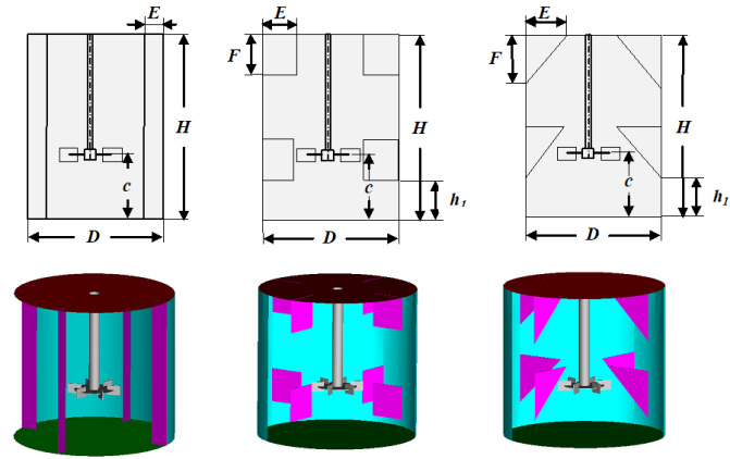
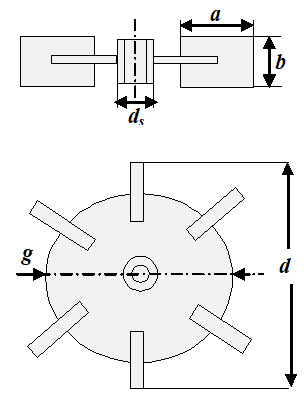
The dimensions of the agitators and baffles are presented in the Tab. 1.
GOVERNING EQUATIONS
The flow in a stirred vessel can be solved using equations that describe the conservation of matter and the amount of movement in Navier-Stokes equations. Moreover, the equations are written in their averaged form RANS (Reynolds Averaged Navier-Stokes) which is used in the case of turbulent flow. These equations establish a connection between the velocity and pressure at each point of the flow.
Whatever fluid domain we follow in its movement, the fluid remains continuous. There can be no external input or removal of material. The continuity equation expresses the variation of the mass of fluid with respect to time in a given elementary volume. This equation can be expressed as:

For a steady flow:

The continuity equation has become:

The equation of momentum is defined as:



The Reynolds number characterizes the ratio between inertial and viscous forces. For stirred-tank systems, its expression is given as follows:

Where ρ is the density of the liquid, N is the speed of rotation of impeller (ω = 2πN, ω is the angular velocity), d the diameter of the agitator and μ the dynamic viscosity of the liquid.
The dimensionless radial(R*) and axial (Z*) coordinates are given as follows:

Velocities are set according to the blade tip velocity:

Power is a fundamental measure of the design and operation of mechanically agitated vessels. It refers to the energy transferred by an agitator to a liquid. By performing a dimensional analysis of the Navier-Stokes equation, one can derive a dimensionless parameter known as the power number, NP:

where P represents the power consumption of the agitator system.
However, the most accurate way to obtain power is to determine the torque (C) applied to the shaft by adjusting the fluid in motion. Then, the strength can be calculated using the following relationship:

C represents the torque of the agitator system.
In this study, the standard κ–ε model was employed to simulate the turbulent flow. This model is a two-equation formulation that describes turbulence using two transport equations: one for the turbulent kinetic energy (κ) and another for its dissipation rate (ε).


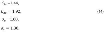
In general, for free turbulent flows at high Reynolds numbers, the values of the various constants are as follows.
The constants C1ε, C2ε, σk and σε in both equations (14) and (15) are obtained from experimental data from a variety of flow patterns.
Pκ is the production of turbulent kinetic energy due to viscous forces and gravitational forces Pκb (buoyancy forces).

The term gravitational forces Pκb, is modeled by the formula:

Prt is the turbulent Prandtl number for energy.
NUMERICAL SIMULATIONS
In this study, the commercial software CFX 18.0 was used to simulate 3D flow fields in stirred vessels equipped with three types of baffle shapes: vertical baffles (VBR), square baffles (SBR), and triangular baffles (TBR).
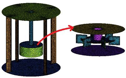
The geometry was created and meshed the computational domain with a tetrahedral mesh (Fig. 3).
The geometry was created and meshed the computational domain with a tetrahedral mesh (Fig. 3). Increased mesh density was used near the impeller and tank walls to capture the flow details at the boundary layer. The domain is divided into two distinct zones: a rotating zone that describes the rotational motion of the fluid around the impeller, which is discretized with 188,773 nodes, and a stationary zone consisting of tank walls and baffles, which is discretized with 530,208 nodes.
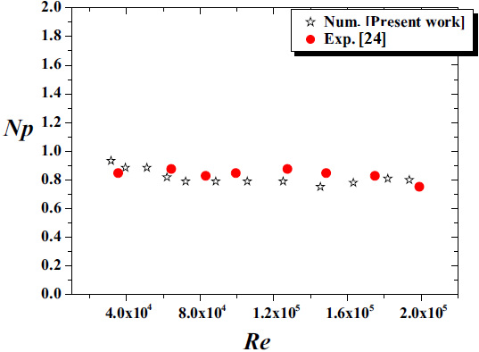
To verify grid independence, simulations were performed using different mesh densities. For the mesh with 636,249 nodes, the calculated power number was 0.859 for Re=105, whereas the experimental value reported by Karcz and Major [24] is 0.83, resulting in a deviation of approximately 3.3%. For finer meshes with 718,981, 908,954, and 1,099,672 nodes, the differences in power consumption compared to the experimental data were reduced to 1.56%, 1.32%, and 1.3%, respectively. These results indicate a noticeable stabilization of the solution for the second and third mesh configuration.
The boundary conditions are introduced in ANSYS CFX-Pre code using the multiple referential frames (MRF) method. In this approach, the fluid flow fields are connected at the interior surfaces (interface) separating the two domains using the frozen rotor method. The simulation was performed on a Pentium (R) Core i7 with 8.0 GB of RAM, and convergence was typically achieved after 3-4 hours of computation.
RESULTS AND DISCUSSION
Validation
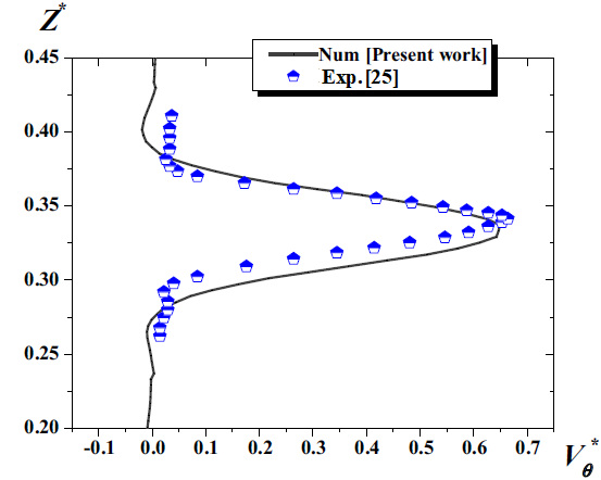
In this section, our predicted results are compared and validated against the experimental data reported by Karcz and Major [24] and Wu and Patterson [25]. Figures 4 and 5 show the power number and the tangential velocity profile along the tank height at R* = 0.185 for a flat-bottomed tank equipped with full-length baffles (F). As illustrated, the numerical predictions closely match the experimental measurements provided by the referenced authors.
Effect of the baffle configuration
In this study, in this study, a detailed hydrodynamic investigation of a vessel stirred by a Rushton turbine equipped with different types of baffles is carried out using the CFD method. As a first step, we examined the effects of three baffle configurations inside the vessel: vertical baffles (VBR), square baffles (SBR), and triangular baffles (TBR). Baffles are essential elements in agitation mechanisms; according to the literature, four uniformly distributed baffles represent an optimal configuration, as they significantly alter the predominantly tangential flow into a three-dimensional flow pattern, leading to improved mixing efficiency, lower power number compared to other configurations, and an increase in power consumption due to enhanced flow resistance.
The flow fields for the cylindrical vessel fitted with VBR, TBR, and SBR baffles are shown in Fig. 6. The results indicate that, for all configurations, the maximum velocity intensity is located near the blade tips. The turbine divides the flow into two main streams: one directed toward the bottom of the tank and the other toward the free surface, leading to the formation of two vortices above and below the impeller. A comparison of the three configurations shows that the vessel equipped equipped with SBR baffles exhibits a noticeable reduction in the upper vortex size compared to the VBR and TBR cases.
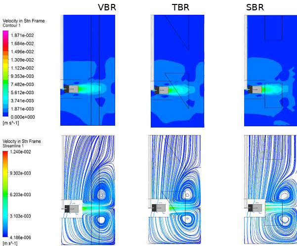
Fig. 6. Distribution of velocity fields at the plane level for different agitators (VBR, TBR and SBR) for Re = 4×10⁴
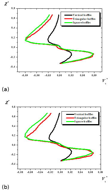
Fig. 7. Axial velocities for different configurations (VBR, TBR and SBR) for Re = 4×10⁴, for (a) R* = 0.305 and (b) R* = 0.333
Fig. 7 shows the axial velocities for the different baffle types at two locations, R* = 0.305 and 0.333, for a Reynolds number of 4×10⁴. It can be observed that the axial velocity curves are identical and similar. The axial velocities have low values near the free surface of the liquid and near the turbine for the tank equipped with VBR, and higher values near the turbine, reaching 0.02. In addition, a strong fluid jet develops near the turbine in the cases with TBR and SBR, with maximum values of 0.09 (Figure 8a) and about 0.07 (Figure 8b) at both locations (R* = 0.305 and 0.333). The SBR configuration also shows higher velocities near the free surface of the liquid, reaching approximately 0.03.
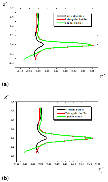
Fig. 8 shows the radial velocities of agitated tanks fitted with three types of baffles (VBR, TBR and SBR) at two locations (R* = 0.305 and 0.333) and with a Reynolds number (Re) of 4x10⁴. The radial velocities for tanks with TBR and SBR are identical, with maximum values of 0.36 and 0.03 at R* = 0.305 and 0.333, respectively. However, there is a significant difference in the lower part of the SBR tank, with values of 0.09 and 0.1 compared to the other tanks.
Effect of Reynolds number
The effect of the Reynolds number is being studied. Three different geometric configurations were tested with Reynolds numbers of 6x10⁴, 8x10⁴ and 105. These configurations include cylindrical tanks with three types of baffle tank: VBR, TBR and SBR, respectively.
Fig. 9 shows the streamlines for the different baffle configurations (VBR, TBR and SBR) at various Reynolds numbers. Upon comparing the results, it is evident that the height of the upper vortex increases with the rise in Reynolds number in all cases. This is because the turbine generates a more turbulent flow, which creates a more unstable flow.
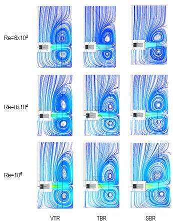
Fig. 9. Velocity fields of streamlines at the plane for different agitators (VBR, TBR and SBR) at various Reynolds numbers
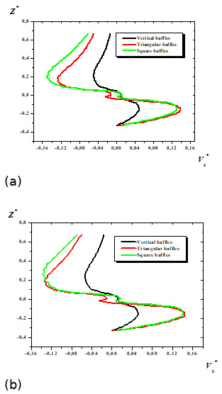
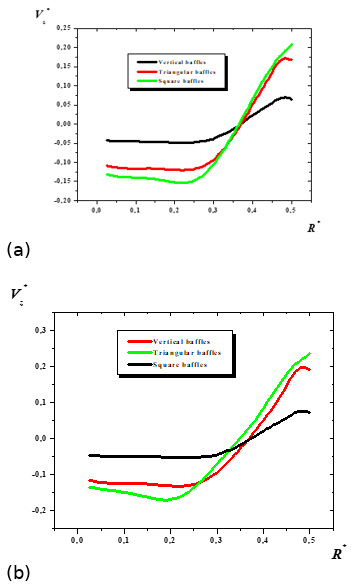
Fig. 10. Axial velocities for different configurations (VBR, TBR and SBR) for R* = 0.25, (a) Re = 8×10⁴, (b) Re =105
Fig. 11 plots the axial velocities for various baffles at Z* = 0.25 and for Reynolds numbers of 8×10⁴ and 105. The axial velocity remains almost constant under the turbine at locations R*= 0 to 0.25, and then increases until reaching a maximum value of approximately 0.2 and 0.25 under the turbine for cylindrical tanks with SBR (Fig. 11(a) and 11(b)).
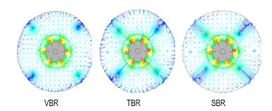
Fig. 12 shows the speed vectors for baffled tanks with three types of agitators (VBR, TBR, and SBR) and Reynolds number Re = 8×10⁴ in the r-θ plane. The baffles act as obstacles that slow down the fluid. On comparison, we can observe that the intensity of vectors increased around the turbine and formed a few recirculation zones between the baffles and tank walls.
Power consumption is a globally significant parameter that describes the performance of a mechanically agitated system.
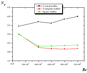
Fig. 13 illustrates the results for different Reynolds numbers. The figure illustrates that cylindrical tanks with TBR and SBR, followed by VBR, have values of approximately 4.3, 4.4, and 6, respectively, at a Reynolds number of Re = 105.
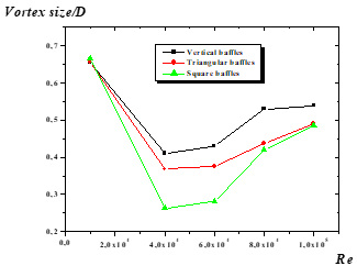
Fig. 14 shows the size of the vortex in agitator tanks fitted with three types of baffle tank (VBR, TBR and SBR) at Reynolds numbers between 104 and 105. It can be seen that agitator tanks with SBR baffles have a smaller vortex than those with VBR or TBR baffles. Vortex size values start at 0.66 at Re= 104, decrease to 0.25 at Re = 4×10⁴, and then increase again to 0.48 at Re= 105.
Effect of baffle width
The effect of the baffle width is examined as shown in Figure 15, using four different geometrical configurations with different ratios: E/D = 9/40, 1/4, 4/15 and 3/10. Fig. 15 presents the velocity contours and streamlines for various widths of square baffles configuration (SBR) at a Reynolds number of Re = 4×10⁴. It can be seen that the volume swept by the turbine decreases and the vortex size increases as the length and width of the SBR configuration in the upper part of the turbine increase. In case (a) (E/D = 9/40), the upper vortex size is significantly reduced compared to the others.
Fig. 16 indicates the velocity contours and streamlines plotted on a horizontal r-θ plane at the mid-height of the impeller blades. Comparing the cases reveals that the jet produced by the turbine fills most of the tank's volume (F/D = 9/40), before decreasing as the length and width of the square baffle increase. Additionally, recirculation zones form behind the square baffles. Recirculation initially occurs at a low volume (F/D = 9/40) and increases successively as the length and width of the (SBR) increase.
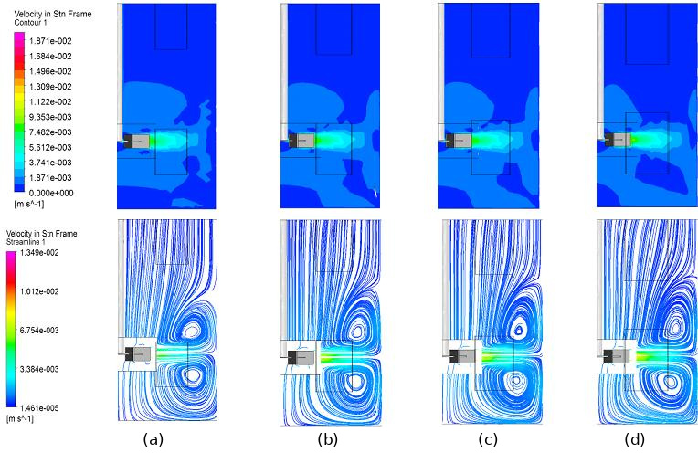
Fig. 15. Flow fields for different widths of square baffles configuration (SBR), Re = 4×10⁴, (a) E/D = 9/40, (b) E/D = 1/4, (c) E/D = 4/15, (d) E/D = 3/10
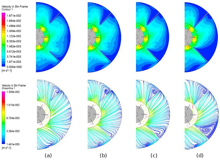
Fig. 16. Flow fields for different widths of square baffles configuration (SBR) at the horizontal r-θ plane, Re = 4×10⁴, (a) E/D = 9/40, (b) E/D = 1/4, (c) E/D = 4/15, (d) E/D = 3/10
Fig. 17 illustrates the distribution of axial velocity for different lengths and widths of the square baffles at radial locations R*= 0.216 and 0.333, and angular position θ = 0°, at a Reynolds number of Re = 4×10⁴. The maximum velocity values are observed near the turbine for the square baffles at vertical positions Z*= 0.18 and -0.15 at R*= 0.216, and at Z*= 0.026 and -0.026 at R*= 0.333.
Fig. 18 presents the tangential velocities for different square baffle lengths (SBR) along the vessel radius at R* = 0.216 and 0.333, with a Reynolds number of Re = 4×10⁴. The profiles of tangential velocity are almost identical for the ratios E/D = 9/40 and 1/4, as well as for E/D = 4/15 and 3/10. The maximum tangential velocity component is observed at the blade tip of the Rushton turbine (V*θ = 0.7 and 0.35), at R* = 0.216 and 0.333, respectively, for the ratio E/D = 4/15 and 3/10, and weakens near the free surface of the liquid. A significant value is observed in the lower part of the turbine (V*θ = −0.17 and −0.11) at the vertical position Z* = −0.32 for the E/D ratio of 4/15.
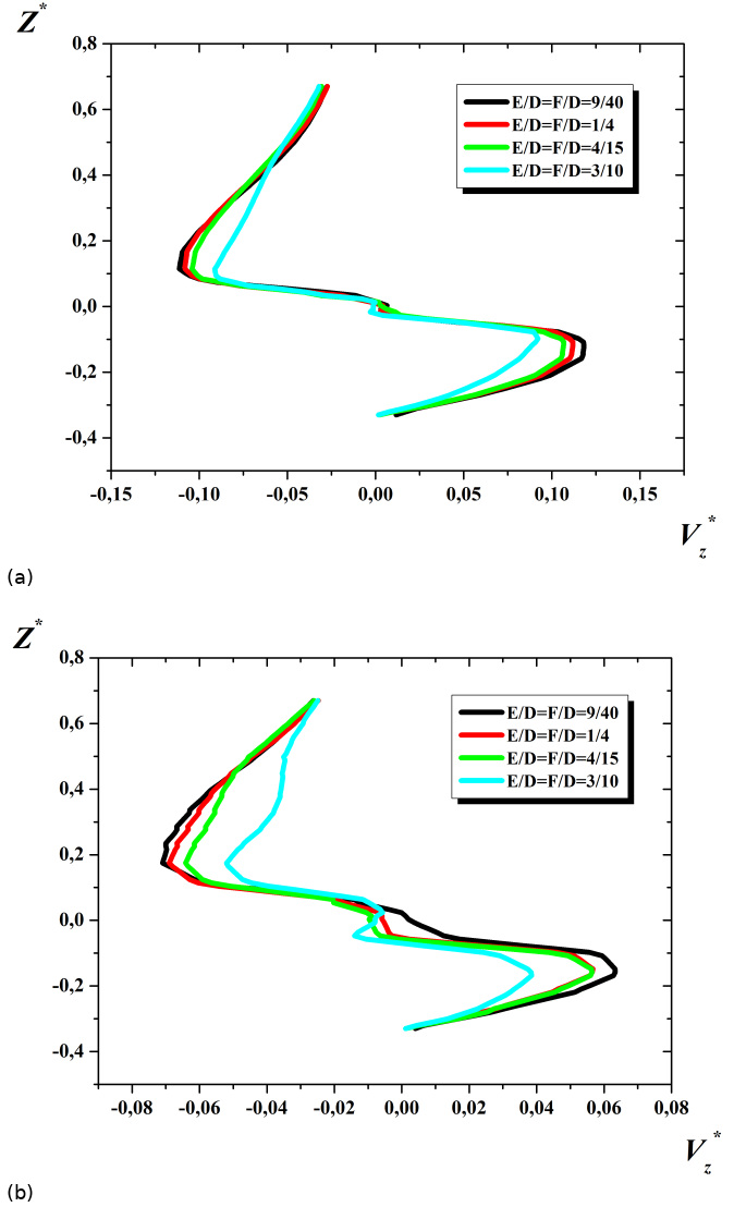
Fig. 17. Axial velocity profiles for different widths ratio of square baffles configuration (SBR) for Re = 4×10⁴, (a) R*= 0.216 and (b) 0.333
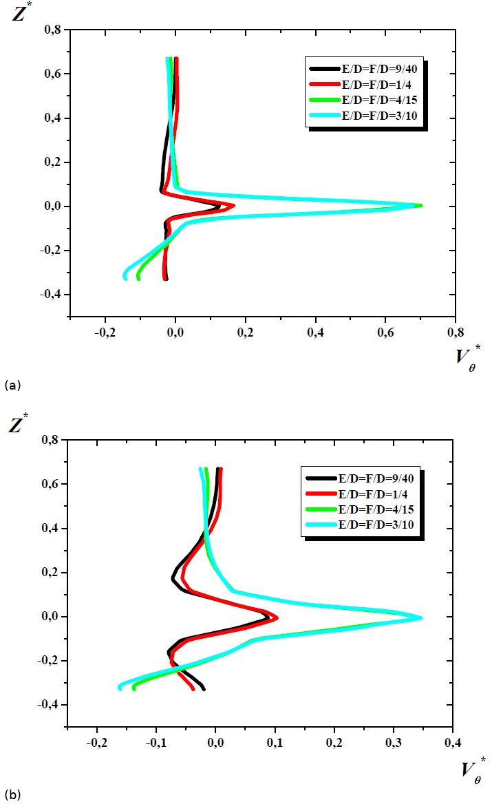
Fig. 18. Tangential velocity profiles for different widths ratio of square baffles configuration (SBR) for Re = 4×10⁴, (a) R*= 0.216 and (b) 0.333
Fig. 19 presents the vortex sizes generated above the impeller for various values of the SBR ratio (E/D) with Reynolds number Re = 4×10⁴. An increase in vortex size is observed with an increased baffle ratio. We found that the ratio E/D = 9/40 results in reduced vortex size compared to the other cases studied.
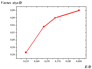
Fig. 19. Vortex size for different widths ratio of square baffles configuration (SBR) for Re = 4×10⁴
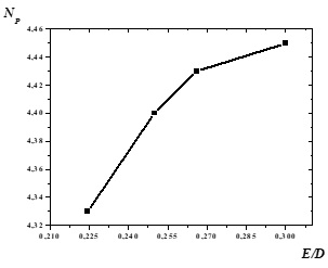
Fig. 20. Power number for different widths ratio of square baffles configuration (SBR), for Re = 4×10⁴
Fig. 20 illustrates the results of the power number (NP) for different values of the square baffle's ratio (E/D). An increase in power consumption is observed with an increasing square baffle's ratio. The case of E/D = 9/40 gives the minimum value of the power number at 4.33. Then, the power number gradually increases until 4.45 for E/D = 3/10.
CONCLUSIONS
The present work aims to analyze the influence of baffle geometry on turbulent flow in a vessel stirred by a Rushton turbine. Three types of baffles were examined: vertical baffles (VBR), square baffles (SBR), and triangular baffles (TBR). The study focuses on how these configurations affect power consumption and vortex formation. Based on the numerical simulations performed, the following conclusions can be drawn:
Agitated tanks equipped with SBR exhibit a noticeable reduction in vortex size compared to the configurations with VBR and TBR. At a Reynolds number of 105, the vortex size values for TBR, SBR, and VBR are approximately 4.3, 4.4, and 6, respectively. The results highlight the superior performance of square baffles, which reduce power consumption by about 2.85% compared with the triangular baffles (TBR) and by nearly 30% relative to the vertical baffles (VBR).
The dimensionless axial and radial velocity components reach their maximum at the upper and lower edges of the Rushton turbine blade tip for tanks equipped with SBR and TBR. These configurations also generate significant velocity magnitudes near the free liquid surface.
The effect of square baffle width (E/D) was evaluated using four geometrical configurations: E/D = 9/40, 1/4, 4/15, and 3/10. The configuration with E/D = 9/40 provided the most effective reduction of the upper vortex size compared to the other cases. This configuration also minimized the recirculation zones forming behind the square baffles, leading to decreased power consumption and smaller vortex structures.
Finally, the tangential velocity component reaches its maximum near the Rushton turbine blade tip along the vessel radius, specifically at R* = 0.216 and R* = 0.333 for the ratios E/D = 4/15 and 3/10. This component becomes very weak near the free liquid surface.
Nomenclature
Greek Letters