
Introduction
For thousands of years, humans have used land and water to navigate terrain, but air travel has revolutionized many aspects of our lives. Recent advances in materials and electronics have led to the development of portable aerial robots, which can be either user-operated or autonomous. Research is underway to enhance the autonomous capabilities of these unmanned aerial vehicles (UAVs), classified as fixed-wing, rotating & flapping wing, hybrid wing, and gas envelope [1]. Among these, quadcopters, a type of rotating & flapping-wing aircraft, are widely used and have numerous applications in disaster management, defense, cinematography, agriculture, and beyond. UAVs can also be categorized by size, ranging from nano to large, depending on their dimensions [2]. As we transition from the nano to larger drones, both computing power and costs begin to rise.
However, nano aerial vehicles (NAVs) have garnered significant interest in educational research and initial testing of aerial algorithms due to their potential for autonomous maneuvering in indoor and outdoor environments. Since global positioning systems (GPS) are not available indoors, localization of NAV in the environment becomes a crucial challenge. To navigate the surroundings, NAV must localize itself in the environment by obtaining its 3D pose with respect to the environment and heading angle. Localization using internal sensors, such as an inertial measurement unit, can be robust for a short duration but is prone to drifting in 3D space when used for longer periods [3]. Additionally, NAVs are small and have limited payload capacity, making it challenging to accommodate various sensors. As a result, researchers have explored alternative localization methods for indoor drone applications.
To tackle the localization problem in an indoor environment, various techniques have been proposed to develop indoor positioning systems by adding artificial landmarks or beacons at known locations such as ViCon [4], radio frequency-based (RF) localization system [5], and distributed sensor systems [6]. Even though these localization techniques achieve excellent accuracy and performance, they are costly and only affordable for some research fields.
Fig. 1 compares the cost of different localization techniques with different types of drones. Researchers have also developed techniques for indoor localization using vision-based approaches. These approaches employ fiducial markers such as AprilTags [7], ArUco markers [8] or circular markers [9] and an onboard camera. They are capable of position estimation of the marker in the camera video stream. However, these approaches demand an onboard computational sensor processing unit for such localization algorithms. This is elevated by sending the sensor data to the ground station to run a computation-heavy localization algorithm [10]. However, the ground station approach suffers from the latency and communication gap between NAV and the ground station.
A viable solution is to localize the NAV using a vision-based system. Recently, WhyCon, an efficient, fast, and low-cost open-source localization system, has been presented [9]. It uses off-the-shelf components and circular markers for localization. This system requires no special equipment to set up the controlled environment. A lightweight and low-cost robotics swarm implementation using the WhyCon system is presented in [11]. It has been shown that the WhyCon localization system outperforms ArUco and OpenCV by a hundred times in terms of processing time [12]. However, the foundational WhyCon system does not provide a unique ID of the target pose, making it difficult for fast control loop applications such as swarm NAVs [13].
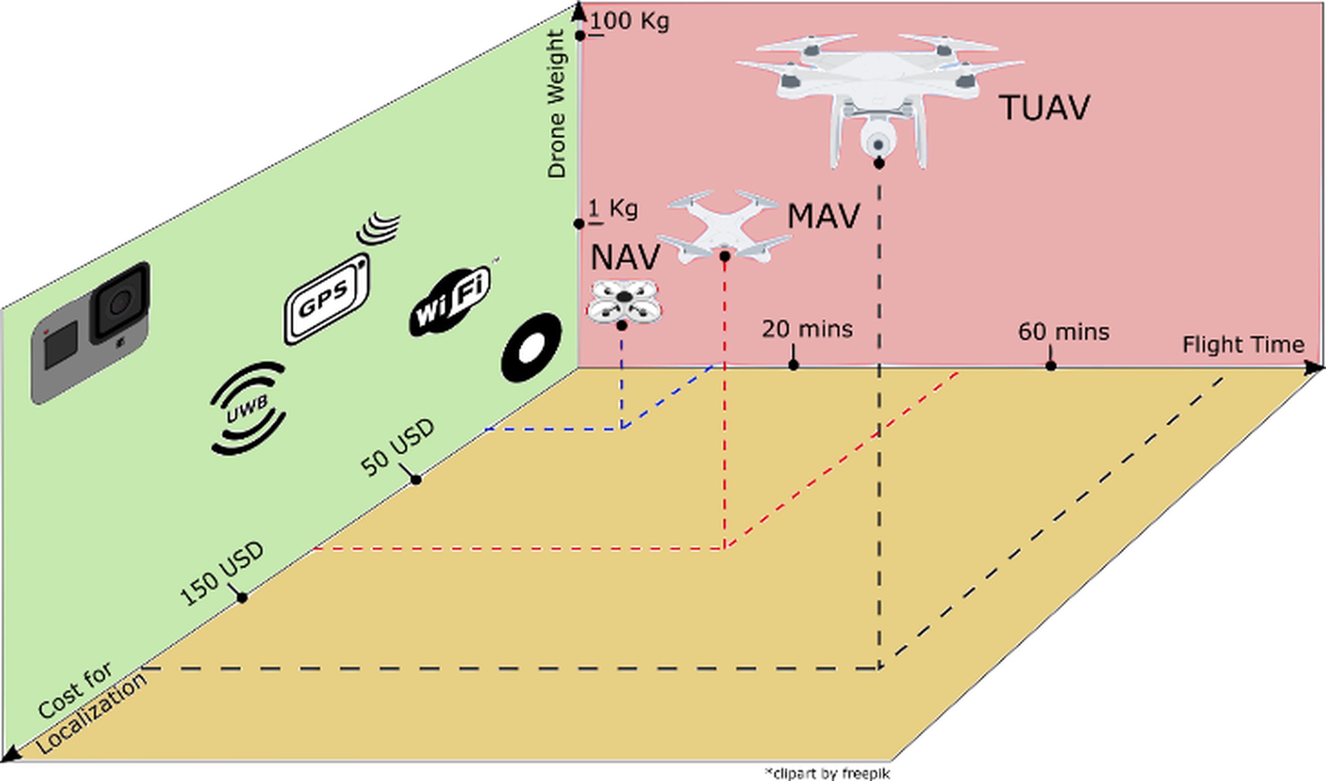
Fig. 1. Comparison between flight time, drone weight, and cost for localization of nano aerial vehicle (NAV), miniature aerial vehicle (MAV), and tactical unmanned aerial vehicle (TUAV). Using NAV along with WhyCon marker for localization substantially reduces the setup cost
The major contributions of this paper are as follows:
Design of a localization-controlled environment for NAV using a WhyCon system (open-source) that is low-cost, easy to set up, and accurate, as illustrated in Fig. 4.
Design of complete architecture of localization system, control commands, and communication protocol around NAVs.
Validation of the proposed localization system by implementing applications such as landing on the objects in motion, autonomous path-planning, and multi-NAV control.
Public release of the package developed to maneuver the NAV in the controlled environment at
https://github.com/simmubhangu/eyantra_drone
While all the individual components of our system may not be novel, to our knowledge, our novelty lies in the integration of a complete system that has been tested on various applications suitable for a low-cost academic environment. The rest of the paper is organized as follows: Section 2 reviews the existing and related work on vision-based localization systems for NAVs, Section 3 provides the details of the localization setup and experiments, Section 4 presents the control architecture for NAV, and Section 5 lists the various applications designed on the proposed technique.
Background And Related Work
In this section, we delve into the related work and background of the components employed in the proposed architecture, including the NAV, state-of-the-art vision-based techniques, and the control algorithm designed for NAV.
Related Work
There have been several implementations of indoor localization systems in the literature. Some of the early work focused on placing artificial landmarks [14, 15] in an unknown environment for object tracking. Even though Vicon-460 [14] system provides an overall accuracy of 65±5µm, these approaches remain costly and
are not viable for every research field. This issue has motivated researchers to look into low-cost localization systems. As an alternative, various marker-based localization techniques have been developed [7, 8, 9, 16]. These markers consist of different patterns; some encode data into them. These patterns are detected using vision algorithms, which provide the pose, angle, and information encoded in it if it exists. A comparative analysis of marker-based localizations has been outlined in [12], revealing that the WhyCon marker stands out for its speed and reduced computational demands [9, 17]. This advantage is attributed to its straightforward encoding and tracking technique.
All the localization techniques mentioned above can localize a UAV in the environment. Different variations of these techniques have been proposed in the literature. For example, researchers were pasting the fiducial markers on the wall at a known location and localizing the UAV using onboard vision processing or relative localization [18, 19]. The implementation of indoor localization using an onboard camera and computing is presented in [20]. The implementation in [17] requires an onboard camera, onboard computing, and a fixed fiducial marker on the wall. However, these techniques require a high payload-carrying capacity for sensory elements, which is difficult for NAVs.
Many low-cost techniques for vision-based localization have been presented in the literature, such as maintaining a geometric pattern visible to another aerial vehicle [18]. This approach is straightforward and relies solely on off-the-shelf components. However, it necessitates on-board computing, restricting processing capabilities. Alternatively, other vision-based techniques utilizing stereo vision have been proposed to alleviate on-board computation [21]. The architecture suggested in [21] computes real-time 3D coordinates, providing this feedback to the UAV. Yet, this method involves a comprehensive stereo-vision preprocessing pipeline, limiting the update rate to 10Hz. Following this, a detailed breakdown of the key components is presented individually.
Nano Aerial Vehicle
Unmanned aerial vehicles are categorized based on payload capacity and flight time. As illustrated in Fig. 1, various aerial vehicles are compared in terms of flight time and localization cost. Given the focus of this study on designing an affordable localization system for low-cost drones, the investigation is confined to NAVs.
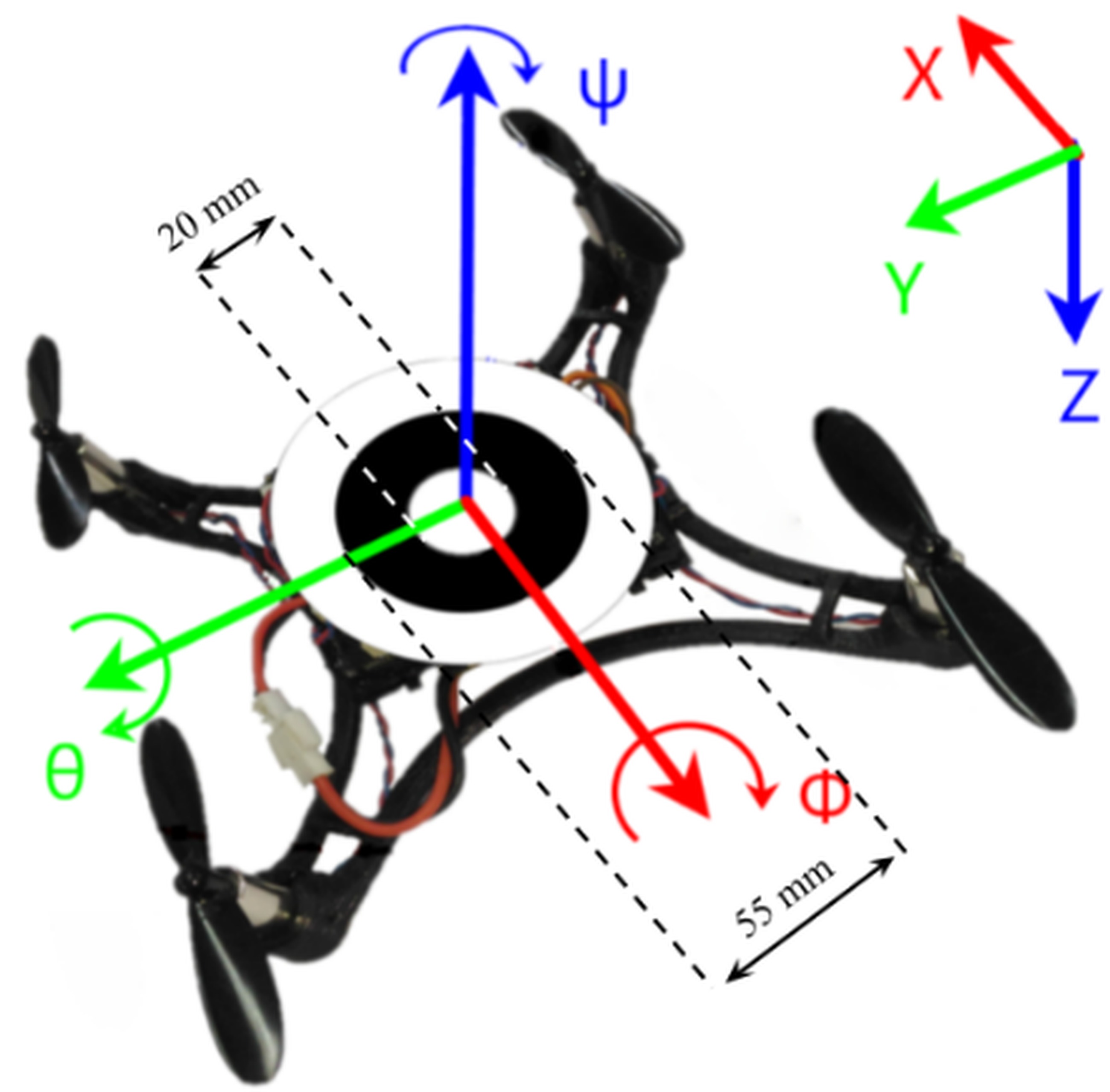
The NAV utilized in this experiment is “Pluto X," an open-source drone created by Drona Aviation [22], a startup affiliated with the institution. The Pluto X boasts compact dimensions of 9x9 cm, a lightweight profile at 48 grams, and a flight endurance of 7 minutes. It serves as an exceptionally versatile platform for developers. Powered by a 3.7V 600mAh LiPo battery, it can achieve a maximum speed of 3 m/s. Its motor controls facilitate dynamic translation along the x, y, and z axes, as well as rotation about the roll (ϕ), pitch (θ), and yaw (ψ) axes in three-dimensional space, as illustrated in Fig. 2.
The drone has an onboard set of sensors, including a three-axis accelerometer, gyroscope, magnetometer, barometer, and a bottom-mounted laser sensor for height determination. These sensors are internally filtered to provide essential data on roll, pitch, yaw, and altitude. Additionally, the drone features onboard Wi-Fi for bidirectional data exchange and firmware programming directly on the device.
Indoor Localization
The pose data from WhyCon can be used as feedback for external control algorithms. The authors in [9] show that the proposed algorithm in WhyCon marker detection can find patterns approximately one thousand times faster than traditional methods. The fast update rate of the WhyCon algorithm, 80 to 100 Hz, made it suitable for obtaining precise and high-frequency localization information for our control loop to maintain the reference drone pose. Furthermore, the high update rate allowed us to track multiple markers without delaying the control loop of the drone. The WhyCon marker is made of an inner white patch surrounded by a black portion, as shown in Fig. 2. The inner diameter can be reduced or increased. However, changing it affects the z coordinate.
However, the original design of the WhyCon localization algorithm assumes a fixed number of targets within the frame, posing a challenge when endeavoring to change these targets dynamically. This calls for an adaptation of the current algorithm to adeptly handle dynamic targets within the frame.
Control Algorithm
Controllers are designed to produce commands that direct a plant, in this instance, NAV, to reach a specified setpoint within a finite time frame. One such controller, Proportional Integral Deria-
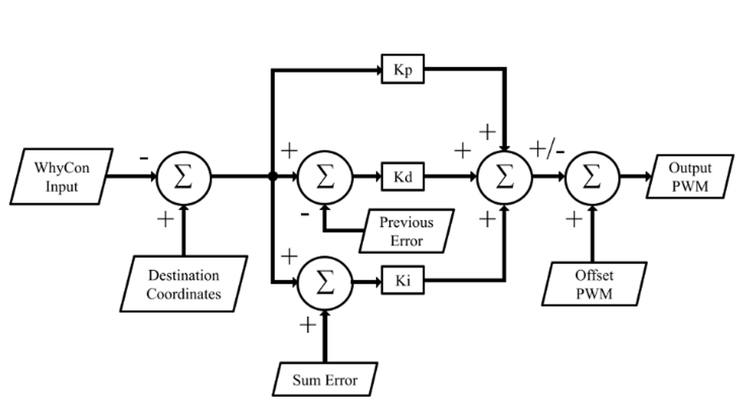
tive (PID) controller is widely adopted in drones [23]. It is a negative feedback control mechanism used to design a system that automatically applies an accurate and responsive correction to a control function and stabilizes at the desired output or reference. As the NAV has four controllable degrees of freedom, we must apply the PID controller to all of them, i.e. ϕ, θ, ψ, and throttle, as shown in Fig. 3. However, the NAV is placed in its starting position so that its yaw is at the desired setpoint with respect to the overhead camera. The internal PID of the NAV makes sure that the yaw remains the same throughout the flight. To this end, we must apply a parallel PID control system to control ϕ, θ, and throttle.
Proposed Localization Setup And Experiments
This section details all the crucial aspects of the proposed localization setup and experiment performed. In subsection 3.1, details about the environment, such as the camera, platform, and drone used, are discussed. In subsection 3.2, the internal controller of the NAV is discussed. In subsection 3.3 localization method using a WhyCon marker is explained, and in subsection 3.4, the process used for calibrating the camera is described.
Custom-Controlled Environment
The setup of indoor controlled environment is shown in Fig. 4. Overhead camera, ELP 2 Mega Pixel Ov2710, is mounted at 3-5 meters. It offers a wide field of view adequate for the NAV to maneuver. The camera has a maximum resolution of 1920x1080 and a maximum FPS of 120. Additionally, the camera provides a large field of view (FOV) of 170 degrees to view most of our controllable environment. As the region enclosed in the controlled environment depends on the height of the camera, the resolution of the frame, and the view angle of the camera, the resolution is set to 640x480 at 120 FPS. A high FPS ensures faster localization information for the control algorithm.
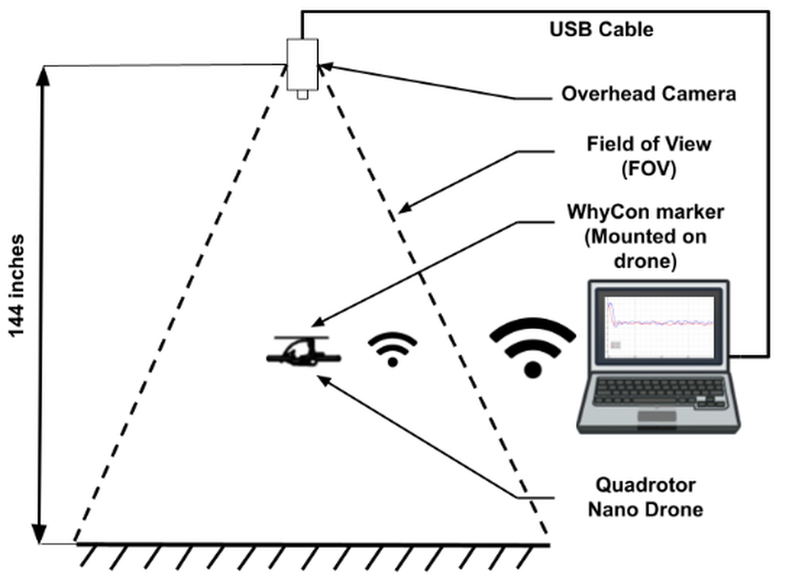
Fig. 4. Arrangement of a custom-controlled localization environment for NAV utilizing an adapted WhyCon system
Robot Operating System (ROS), running on the laptop shown in Fig. 4, is a framework consisting of various libraries and packages that can reduce the complexity of tasks. ROS provides high flexibility, allowing developers to test their work in simulators before working on robot hardware. It provides topics and services to share the data among different live nodes.
The drone’s firmware is built upon the open-source firmware Cleanflight [24], which provides support for Multiwii Serial Protocol (MSP) [25]. Onboard firmware is modified so that it is capable of communicating through MSP via Wi-Fi. Drone-ROS Driver (DRD) is developed for handling the communication of drones with ROS [26]. MSP is a simple and light protocol that communicates coded messages. The messages’ format, direction, and ID are unique and predefined.
Internal And External Control
The NAV has an internally filtered IMU sensor, which is used to regulate the ϕ, θ, and ψ of the drone. It is used to hold the NAV steady at its own axis. We measured its ability to hold the position at a fixed setpoint in terms of WhyCon coordinates with and without our external control algorithm. The error measured is the difference between the setpoint and the drone’s current position in WhyCon coordinates.
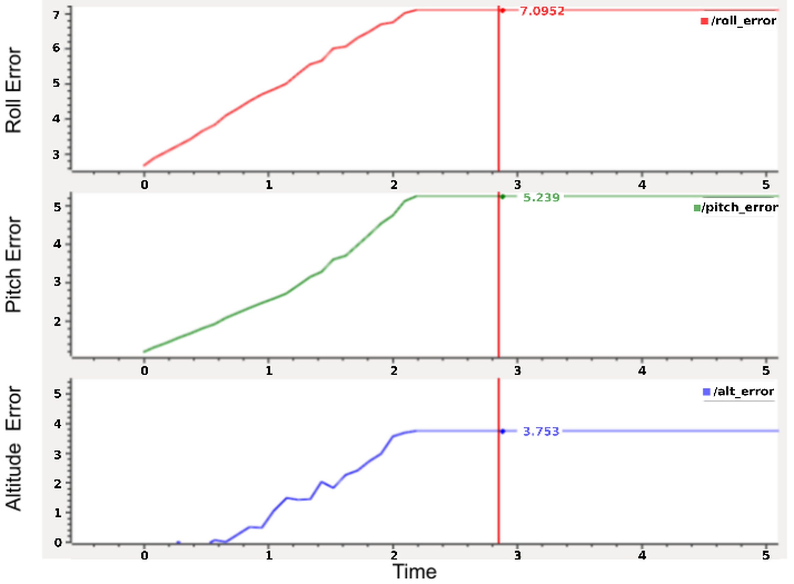
Fig. 5. ϕ, θ, and Altitude error with internal control. As depicted in the graph, there is an evident increase in error of roll, pitch, and altitude with time. This indicates the necessity for an external controlle r
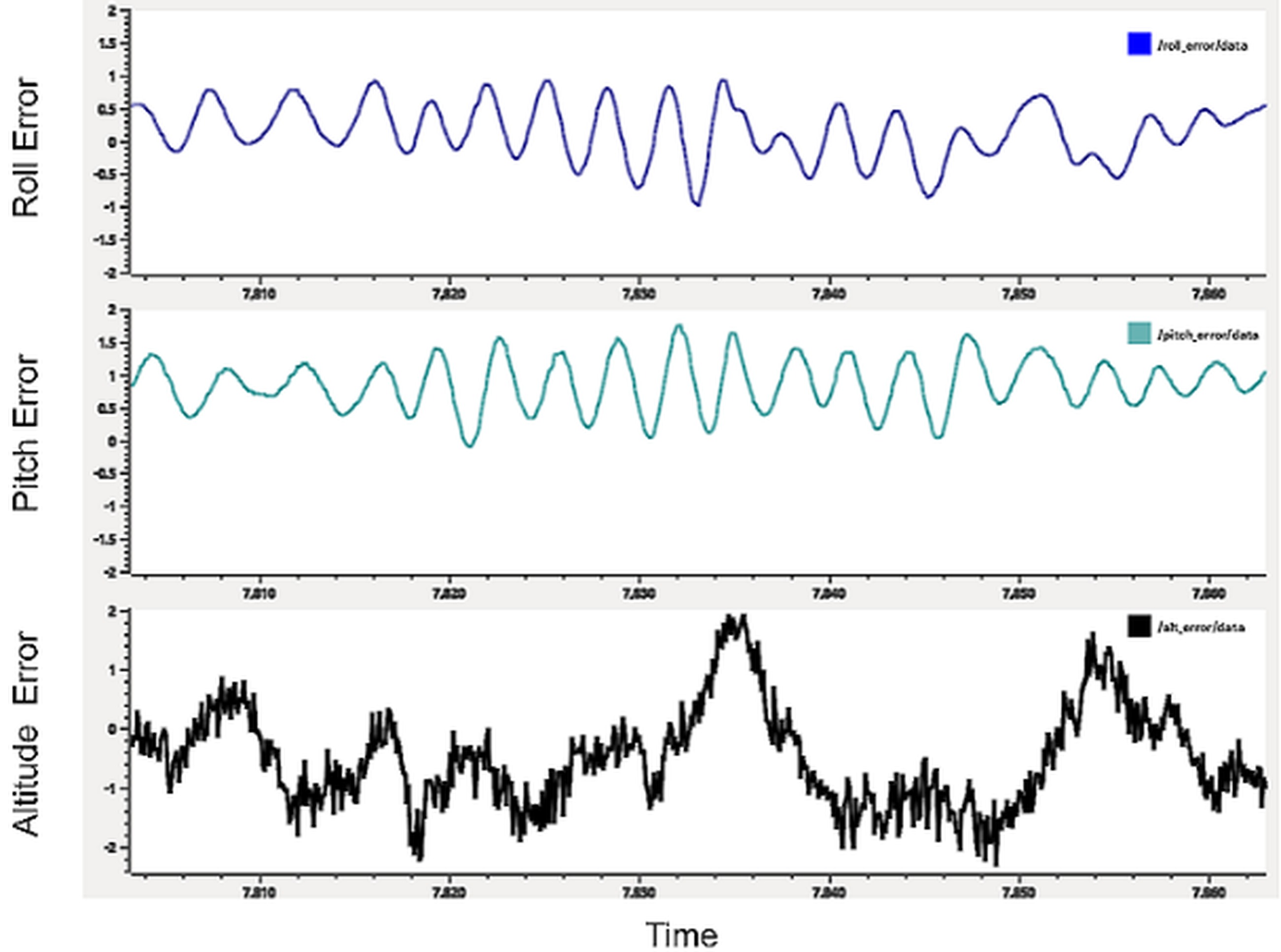
As shown in Fig. 5, the NAV starts at the setpoint but drifts off in all three axes until it is completely out of the frame. The graph flat-lines once it is out of the frame. Maximum error recorded in ϕ is 7.095, θ is 5.23, and altitude is 3.75 WhyCon coordinates. An external control prevents the drone from drifting out of the frame. From Fig. 6, we found that the error in position hold is quite small. Maximum recorded error in ϕ is between -0.9 and 0.8, in θ is between -0.1 and 1.8, and in altitude is between -2.2 and 2. The comparison results show that the NAV itself cannot hold the position without external control. Its onboard sensors are inaccurate and hence fail to localize itself.
Localization Using A Whycon Marker
To obtain the 6 degrees of freedom (DOF) pose of the drone in the real world, we used an external camera to track the drone. The WhyCon visual marker was mounted on the drone to provide this. Although the orientation data is unreliable, the position data from WhyCon is extremely accurate. As shown in Fig. 2, to express the drone coordinate frame (D) in the camera coordinate frame (C), a 180° 3D rotation transform was applied across the y−axis.
In general, let CTD be the homogeneous transformation from the drone coordinate frame (D) to the camera coordinate frame (C). It can be expressed as:
where, CRD is the is the rotation matrix and CtD is the translation matrix. Applying a 180° (θ) 3D rotation across the y−axis, we represent our CTD matrix as:
Camera Calibration
The general image view of USB cameras has a fish-eye view output[27]. However, this is undesirable as it affects the WhyCon coordinates. We need a flat image output from our camera, and hence it is necessary to calculate its parameters. Fish-eye radial distortion has two types - Negative radial distortion or Pincushion distortion and Positive radial distortion or Barrel distortion. In either case, the camera’s intrinsic and extrinsic parameters are used to map the 3D coordinates of an object in the world frame to the 2D coordinates of the image plane generated. The extrinsic parameters of the camera represent the camera’s location in 3D space. It consists of rotation and translation components. These transform an object’s 3D world coordinates to the camera’s 3D coordinates. The intrinsic parameters of the camera consist of focal length and optical center. Via a projective transform, the 3D camera coordinates are transformed into 2D image coordinates. We can calibrate the camera by determining the extrinsic and intrinsic parameters using printouts of a pattern of defined size, for instance, a checkerboard. ROS provides support for calibrating a wide variety of cameras, provided that the camera’s drivers satisfy the ROS camera interface. Using the camera calibrator package, both monocular and stereo cameras can be calibrated. The package is built over OpenCV camera calibration [28] using the transformation as given in Equation 1 where s is the scale factor, (x, y) are the image points (X, Y, Z) are the real world coordinates, (R, t) are the extrinsic parameters of the camera and K is the intrinsic parameter of the camera.
Control Architecture
Position holding of NAV
The WhyCon marker input consists of x, y, and z coordinates which gives the current position of the NAV with respect to the world in WhyCon’s coordinate frame. These coordinates will be used as feedback to maintain the position of the drone at a particular point. Destination coordinates or the coordinates at which the drone must hold its position are denoted by X, Y, and Z. Error (x-X,y-Y,z-Z) between the current position and the destination is fed to the PID controller as shown in Fig. 3. PID controller takes errors as inputs and generates the expected PWM of the motors so that it can move toward the destination coordinates. These errors are used to control the ϕ, θ, and throttle of the drone, respectively. An internal PID of NAV is running independently to stabilize it at its own references as mentioned in subsection 3.2. A proportional controller (Kp) reduces the rise time and gets the drone to oscillate around a point. If that point is not the setpoint, it indicates that the system has a steady-state error. The integral controller (Ki) eliminates the steady-state error. A derivative controller (Kd) increases the stability of the system by reducing the overshoot.
All three PID controllers take new data after a fixed time interval called sample or loop time. Sample time depends upon the worst-case delay to calculate the output of PID in each iteration, as given in Equation 2.
Waypoint navigation of NAV
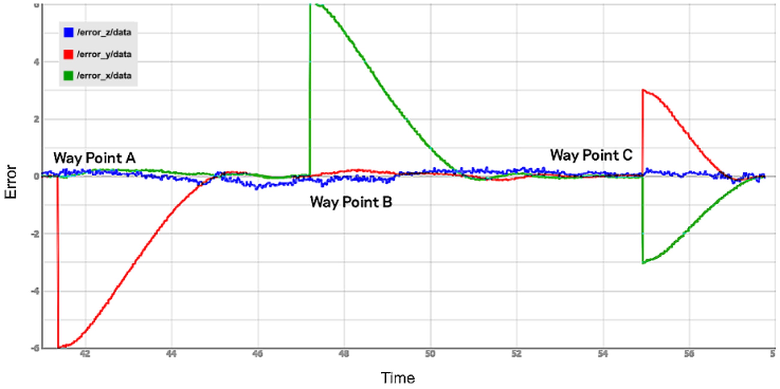
Waypoint is a destination coordinate at which the drone must hold its position. Fig. 7 shows the plot of error in y (error_y/data), x (error_x/data), and z (error_z/data) axes in WhyCon’s coordinate frame vs time at different waypoints.
In Fig. 7, a denotes the point at which a new waypoint (keeping the Z and X same and a different Y) is set. We can see that the rise time is less for the NAV to stabilize at the new setpoint. There is a minimum overshoot and steady-state error, indicating optimum tuning of PID parameters in pitch. B denotes the point at which a new waypoint with a different X is set, and C denotes the point at which both X and Y are changed. Factors like rise time, overshoot, settling time, and steady-state error in the plot indicate appropriate tuning of PID parameters in roll and pitch. Similarly, PID parameters for throttle are also tuned.
Auto-tuning of PID
The method of computing the PID parameters using trial and error is both tedious and time-consuming. Since it involves human intervention, the controller may not be optimally tuned. Auto-tuning of controllers can help to solve the above problems. We will discuss Ziegler-Nichols Method and Iterative Feedback Auto-tuning in subsections 4.3.1 and 4.3.2, respectively.
Ziegler-Nichols method
Many techniques have come up over the years to auto-tune the PID controller after the works of Ziegler and Nichols[29]. It involves relay feedback[30] and pattern recognition[31] techniques. We follow a similar approach as that of [32] in which we induce sustained oscillations and measure PID parameters using Ziegler-Nichols reaction curve method.
We force the controller output to maximum and wait for the NAV to cross over the setpoint. On crossing the setpoint, the controller output is forced to a minimum. This is repeated four to five times to obtain approximately consistent oscillation about the setpoint. This process is repeated for pitch and then roll as well. We consider that the controller gain necessary to maintain this oscillation is Ku and the time period between this oscillation is Tu. Ku is computed as given in Equation 3:
where d is the amplitude of PID output and a is the amplitude of oscillation about the setpoint. The controller can be represented as given in Equation 4:
where, Ti is the integral time constant and Td is the derivative time constant. According to the Ziegler-Nichols method, Tab. 1 establishes the relation between the above-mentioned parameters.
Depending upon the need, an appropriate controller type is selected, and its corresponding equations can be used to compute the required parameters. From the values of Ti, Td, and Kp, we deduce the values of Ki, and Kd as per Equation 5.
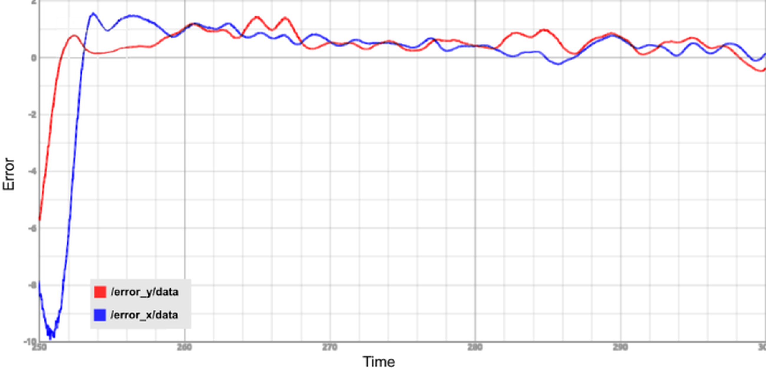
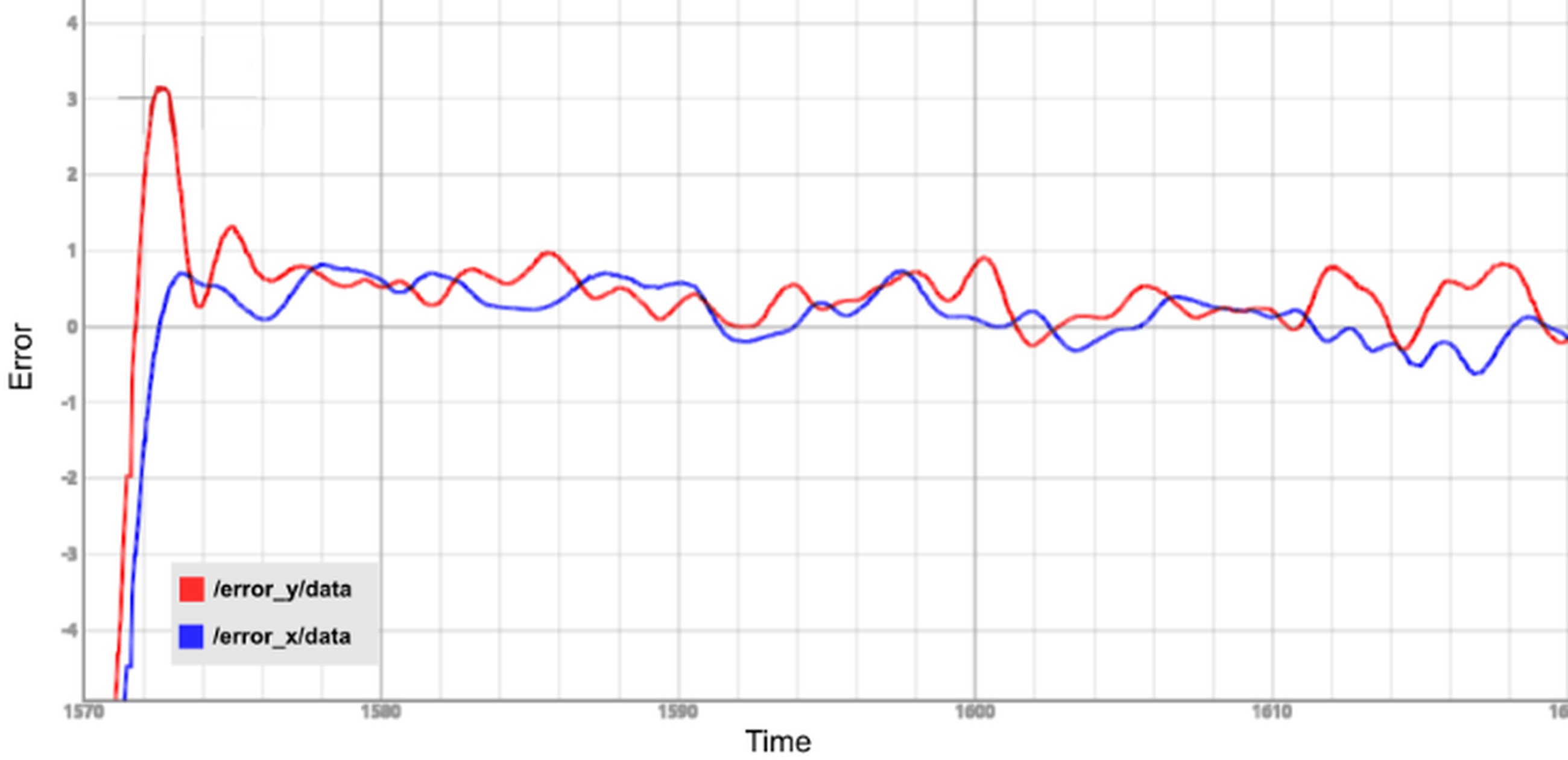
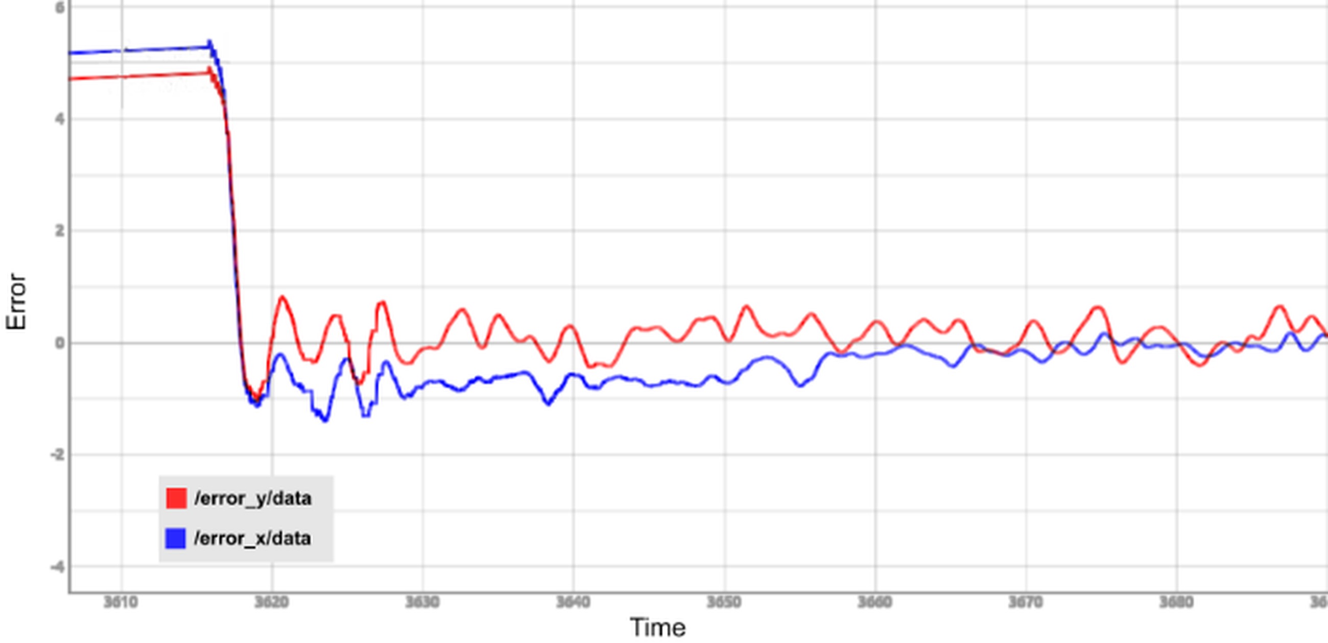
Once Kp, Ki, and Kd are determined they can be used in the previously designed PID controller. Experimental results of different types of controllers tuned in the x and y axes are shown in Fig. 8.
Iterative feedback auto-tuning
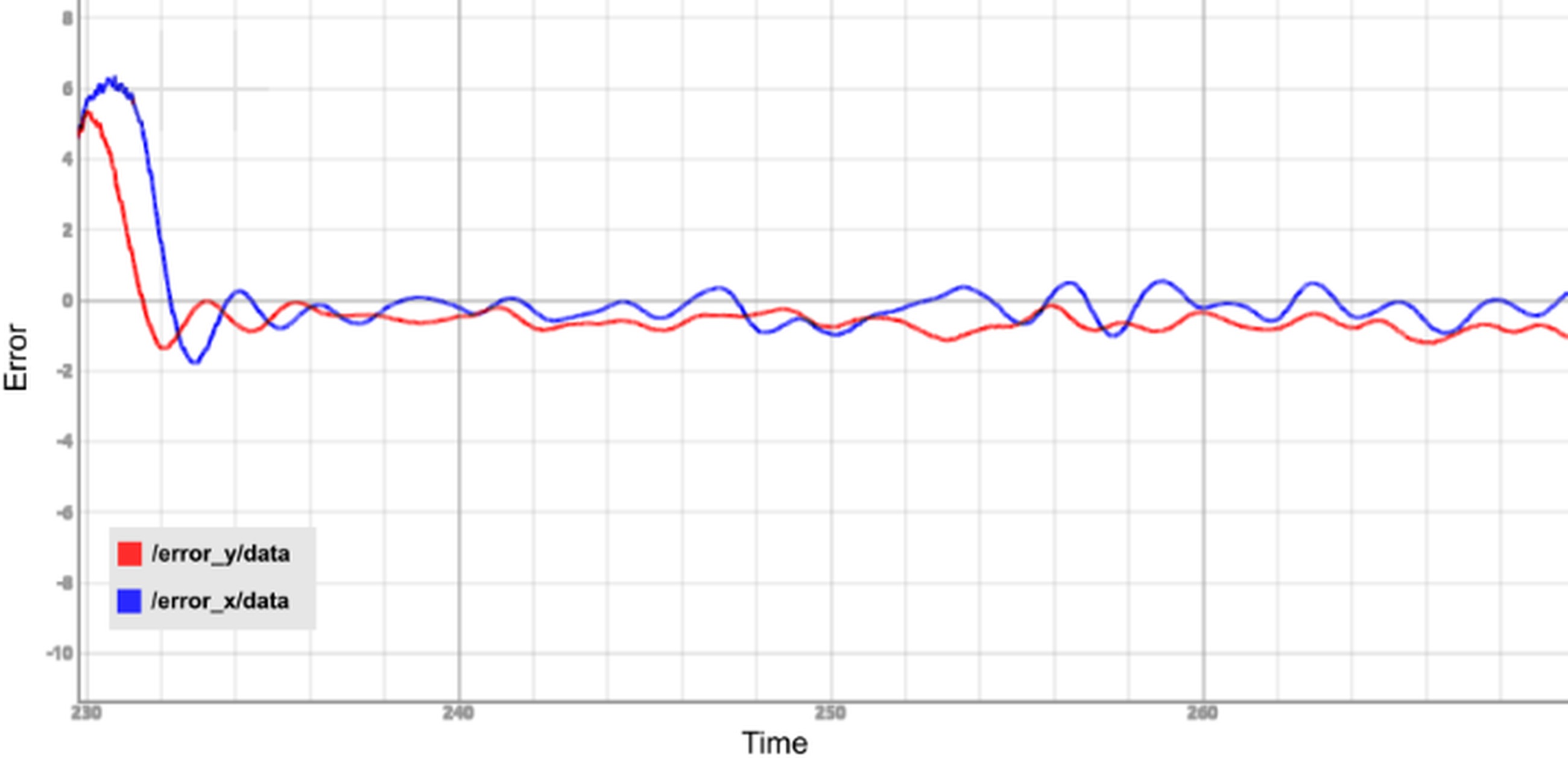
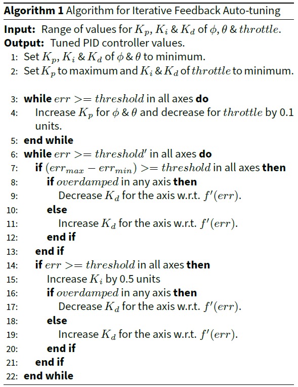
This method calculates optimum values of PID parameters of ϕ, θ & throttle for the controller by tuning during the flight. The user enters a range for the possible values of the parameters and the code continuously changes them based on Algorithm 1. Fig. 9 shows the results obtained for tuning the x and y axes based on Algorithm 1.
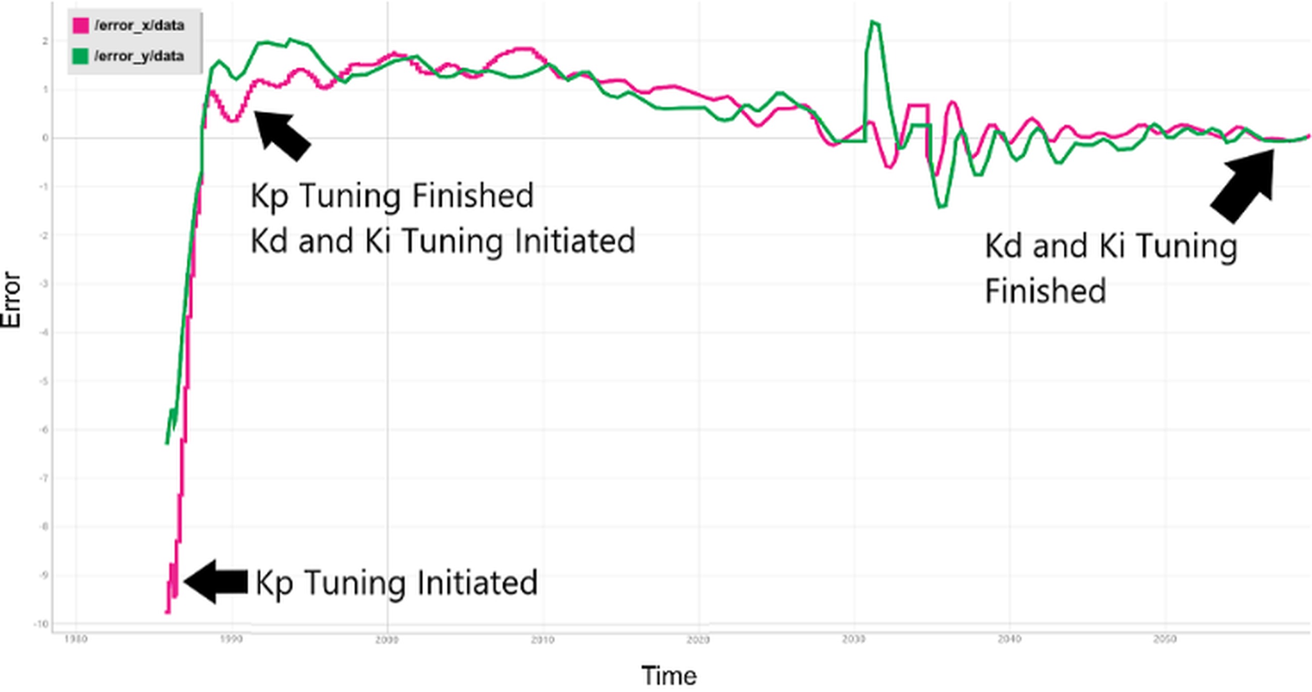
Fig. 9. Plot of error vs time in x(pink) and y(green) axes observed during auto-tuning of the controller as per Algorithm 1. The range of values entered by the user for K_p, K_i & K_d of ϕ, θ, and throttle are used as the starting point for determining the optimum values for these parameters
Applications On Proposed Setup
In this section, three applications are discussed where the proposed system works seamlessly. In subsection 5.1, a novel indoor autonomous landing of NAV on a mobile platform is implemented, in subsection 5.2, indoor path planning of NAV while avoiding obstacles is implemented, and in subsection 5.3, control of multiple drones to create simple formations is implemented.
Autonomous landing on moving platform
Over the last few decades, numerous research groups have dedicated substantial efforts to investigating a variety of techniques for achieving autonomous drone landings. One approach, as outlined in [33], involves the application of color-based image processing algorithms. These algorithms empower drones to perform landings in diverse settings, encompassing both indoor and outdoor environments.
In contrast, other strategies, detailed in [34] and [35], rely on onboard vision systems to identify specific symbols or markers, such as the ’H’ enclosed in a circle, which serve as landing pads in indoor environments. Additionally, the fusion of optical flow sensors and marker detection techniques, as explored in [36] and [37], enhances the precision of landing, especially on moving objects.
Nonetheless, the majority of these methods depend on onboard vision-based detection of landing targets, which imposes limitations on the camera’s field of view (FoV). The fixed FoV, as presented in the proposed methodology, offers an effective solution for autonomous landing on moving objects. It’s worth noting that this technique is most applicable within controlled environments. However, it still holds value as a testing and evaluation platform for algorithms designed to facilitate drone landings on moving targets. In the subsequent section, we will delve into the setup and algorithm for executing autonomous landings on moving targets, as per the proposed methodology.
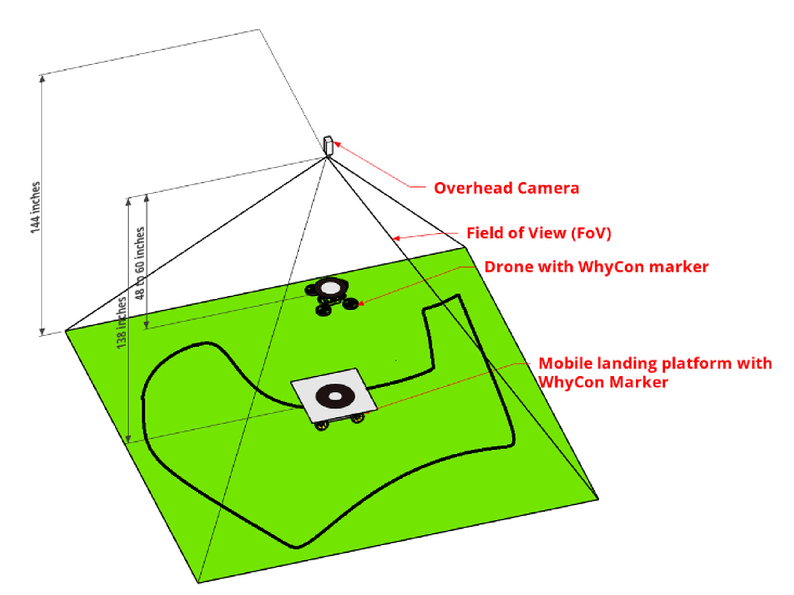
Setup
The entire setup is depicted in Fig. 10. An overhead camera with a fixed Field of View (FoV) is positioned as indicated in the figure. WhyCon markers are affixed to both the NAV and the mobile target. In real-time, the overhead camera employs a modified version of the WhyCon tracking algorithm (for details of the modification, see section 5.1.2) to track these markers. While the mobile target can navigate any path within the controlled environment, its motion is confined to two-dimensional space. As explained in section 3.2, the NAV relies on the overhead camera’s perspective and off-board processing, as its onboard sensors are unable to self-localize. However, the overhead camera effectively tracks the mobile target and issues landing commands to the NAV to ensure a successful landing on the mobile target.
The mobile target in this setup consists of a NEX Robotics differential drive robot [38], an embedded platform equipped with an Atmel AVR ATmega16 microcontroller. To facilitate tracking within the camera’s Field of View (FoV), a WhyCon marker is mounted on the robot. To constrain the robot’s movement within the controlled environment, a flexible sheet with a printed black line is used. This allows the mobile target to move freely in any direction while using the black line as a reference. The localization system, described in Section 3, is employed in this study to determine the 3D pose and heading angle of the NAV.
Controller and algorithm
To achieve an autonomous landing of the NAV on a moving target, it is crucial for the NAV to be aware of the 2D location of the moving target. In our case, this information is provided by the WhyCon marker mounted on the mobile landing platform, which serves as the target’s location (referred to as the set point in this paper). However, due to the random path followed by the target, the changing set point introduces a non-linear error during the error calculation interval, known as the loop time. This nonlinear error, which is directly influenced by the speed of the platform, is determined at each loop time. The varying speed affects the response of the PID; hence, for simplicity within this experiment, the mobile platform was kept at a constant speed.
The proposed algorithm requires tracking two targets at a time. It can be quickly done in the existing WhyCon package. However, this particular tracking algorithm should switch the target tracking objects in FoV at run time for efficient tracking. We modified the existing WhyCon library to handle the run-time target change. According to the modification, the algorithm iterated for the maximum number (‘n’) of the target defined during initialization. If the desired number of markers are not detected in the frame, it issues a service and starts tracking again with an n-1 target in FoV.
Hence, for our application, the predefined number of markers is 2. When the drone hovers/flies over the moving platform, the WhyCon marker detection algorithm in the library fails to detect both markers, which causes the detection algorithm to stop working momentarily. This instability in the detection algorithm affects the PID control algorithm. A marker coordinate feedback was implemented in the control algorithm to solve this detection algorithm problem, since in our application, the z coordinate of the drone is always less than that of the mobile platform, as illustrated in Fig. 10. Every time the detection algorithm stops returning the coordinates of the markers, our service restarts the tracking and changes the predefined value from 2 to 1.
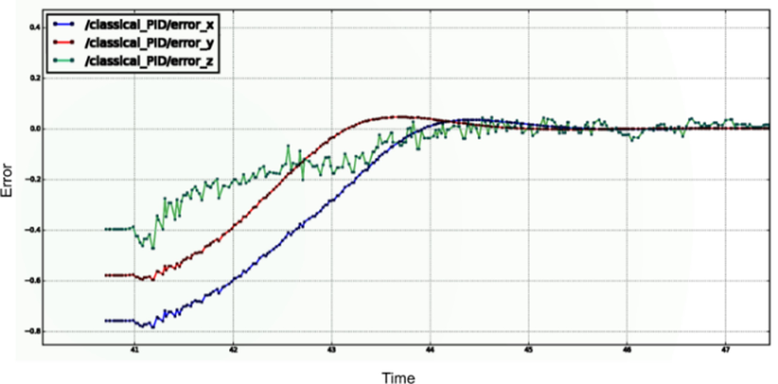
To test the algorithms and environment, we used the Gazebo simulator and the modified Ardrone 2.0 model from tum_simulator. The model featured the WhyCon marker affixed to it. The PID response during the simulation was recorded, and the graph is displayed in Fig. 11.
Path planning and autonomous traversal
Several authors have sought to develop a system for path planning and autonomous traversal of indoor drones. Researchers in [39] have proposed a deep-learning and Line-Of-Sight (LOS) guidance algorithm for autonomous indoor navigation of drones. Others [40] have deployed receiver-side time-difference of arrival (TDOA) based ultra-wideband (UWB) indoor localization for drones. The authors of [41, 42] have used a camera and an Inertial Measurement Unit (IMU) to navigate the drone.
The Swarm of Micro-Flying Robots (SFLY) project [43] uses monocular simultaneous localization and mapping (SLAM) fused with inertial measurements to navigate the drone in a GPS-denied environment. The work described in [44] concludes that the position estimation of the Vicon camera is better than the onboard sensors’ estimation. In search of a low-cost localization system, our application involves the autonomous traversal of a NAV through hoops using WhyCon.
Using three-dimensional path planning, an optimal and collision-free path is found considering various kinematic constraints. Three-dimensional path planning algorithms include Probabilistic Road Maps, bio-inspired planning algorithms, optimal search algorithms like A* & Dijkstra’s algorithm, and random-exploring algorithms like RRT and RRT*. Sampling-based algorithms like RRT offer high time efficiency and are more suitable for real-time implementation [45]. In our work, we use RRT* path planning algorithm because of the higher probability of converging to an optimal solution compared to RRT when obstacles are present [46]. RRT* simply builds a search tree of reachable states by attempting to apply random actions at known-reachable states. The action is considered successful if it does not cause any contact with any obstacle, and the resulting state is added to the tree of reachable states [47]. Implementation of these sampling algorithms is available in Open Motion Planning Library (OMPL). All these planners operate on very abstractly defined state spaces. OMPL plugin is available in many simulation software. In our work, we have used the V-REP simulator (now CoppeliaSim). V-REP has multiple physics engines, mesh manipulation, and most importantly, it provides the user the ability to interact with the world during the simulation run. Compared to Gazebo, V-REP is more intuitive, user-friendly, and consumes less CPU power [48]. Hence, in our work, we are using V-REP as the simulation environment to test the method and later validate the method with a real NAV.
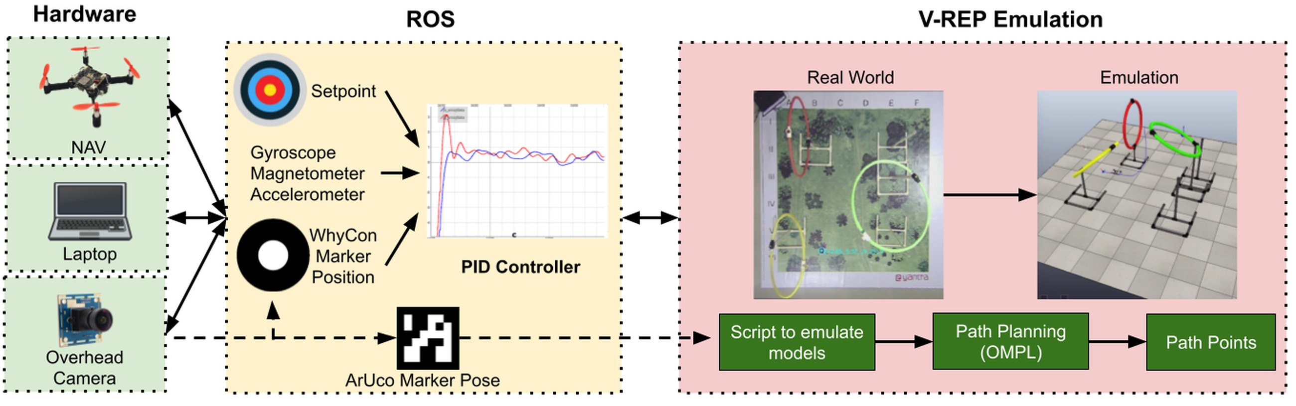
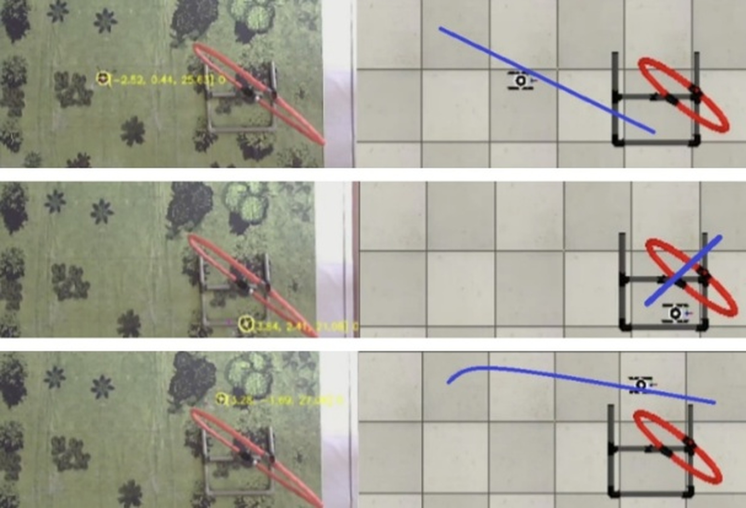
Implementation of the project in V-REP
Testing the algorithm in V-REP involves the modeling of NAV and hoops in V-REP, similar to the ones in the real world, making a V-REP scene for the experimental setup, and the implementation of the algorithm. Calculation of path is done in V-REP using OMPL library. Path points are being published as the required waypoints which are subscribed by the PID controller node in ROS to direct the NAV as shown in Fig. 12.
Modeling of NAV in V-REP
A model is designed in V-REP, which subscribes to the same topic of the same message type as the real NAV. The model is controlled by ROS commands. The model publishes its orientation with respect to the V-REP world. It subscribes to the rostopic drone_command. For eg, to disarm the drone, following command is to be published:
rostopic pub /drone_command pluto drone/PlutoMsg "{rcRoll: 1500, rcPitch: 1500, rcYaw: 1500, rcThrottle: 1000, rcAUX1: 0, rcAUX2: 0, rcAUX3: 0, rcAUX4: 1200}"
Setting up an experimental scene in V-REP
A scene is set up in V-REP comprising an overhead vision sensor and hoops as shown in the Emulation block of Fig. 12. On running the simulation, the vision sensor publishes images of a resolution of 640 x 480 at 30 frames per second. Localization of NAV is done using WhyCon markers. WhyCon node subscribes to the image and publishes relevant output topics.
Computation of path using OMPL
The Open Motion Planning Library, OMPL, consists of many sampling-based motion planning algorithms such as PRM, KPIECE, EST, SBL, RRT, and operates on defined state spaces. Path and motion planning can be done in V-REP using a plugin wrapping the OMPL library. Path planning involves creating a path planning task, creating the required state space, specifying collision pairs, setting start and goal states, and selecting a path planning algorithm, followed by computing the required path. RRT* is the path planning algorithm used here. Multiple paths are computed between the start & goal state, and the shortest path is selected for the NAV to navigate. A minimum of fifty path points are made between the NAV & goal state, and these path points are being published to the NAV as new waypoints to follow. As the nano drone’s flight time is 7 minutes, a maximum time of 20 seconds has been set for each path-searching procedure. Traversal through one hoop involves finding three paths, as shown in Fig. 13. In the worst case, where each path takes 20 seconds to plan and there are three such hoops, it will take three minutes to plan all the paths for all three hoops. The remaining flight time is enough for the drone to maneuver the path.
Emulation of real-world in V-REP
Emulation involves the process of replicating the real world into the V-REP environment so that the computed path points can be directly given as waypoints for NAV to navigate. Input from the WhyCon marker is used to emulate the NAV model. Input from the
ArUco markers [8] are used to emulate the pose of the hoops. An ArUco marker is a square marker composed of a wide black border and an inner binary matrix that determines its identifier. ArUco marker gives the pose of the marker with respect to the camera. After emulating the hoops and obstacles, ArUco markers are removed as the environment is static.
Mapping between WhyCon frame and V-REP frame
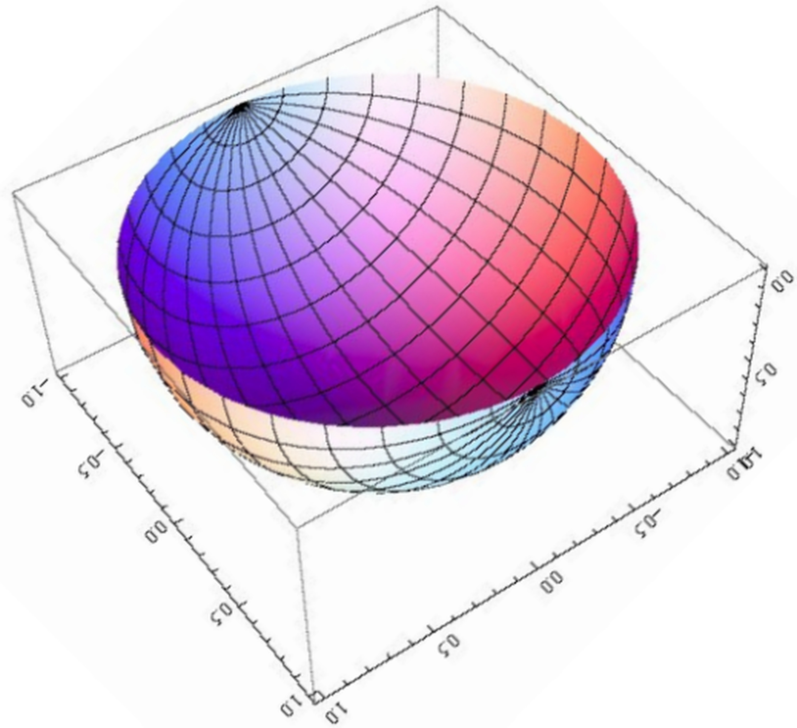
For a given WhyCon marker with an outer diameter of 0.055m and inner diameter of 0.02m, one unit of x and y coordinate approximately equals 10 cm in real or V-REP world. However, even if we keep the marker at the same height, the value of WhyCon’s z-coordinate is not constant when we move the marker along the x or y axis. We observed the trend in the change of the z-coordinate similar to a semi-ellipsoid, as shown in Fig. 14. To minimize this error, we used the equation of an ellipsoid to fit the z-coordinate. WhyCon readings are hence converted to the real world or V-REP world using corresponding scaling factors.
Traversal of NAV through hoops
After converting path points in the V-REP frame to the WhyCon frame of reference, each point is given as a waypoint for the NAV to navigate. The emulation block in Fig. 12 shows the traversal of NAV through hoops.
Multi-drone control
Swarm drones/robots have various applications, both indoor and outdoor. This application focuses on multiple drone control in the indoor environment. When indoor multi-drone localization is involved, sufficient research has been done. Vanhie-Van, G. et al. [49] have summarized the sensor and sensor fusion techniques used in multi-drone localization. The study mainly covered three classes of drones: large, medium, and nano. When the authors analyzed the cost, the sensor cost alone came to 400 USD; in our case, the cost of drones and sensors comes below 100 USD. As seen in Tab. 2, there are a few trade-offs, but our system works better for similar applications and use cases.
Tab. 2
Comparison of the existing systems to our system
In our application, drones perform coordinated motion where each drone follows a specific path relative to other drones within a network. Communication delay has also been calculated and discussed for multiple coordinated tasks in Section 5.3.4. Each drone in the network acts as a client. We used ROS to implement a swarm of drones. In ROS, multiple nodes are created, which are required for communication, localization, and control of formations. Each drone is assigned a unique topic within the network. Drone commands are published on this topic while each drone subscribes to its unique topic and sets its parameters accordingly. The techniques discussed in Section 5.1 were used for localization.
Communication and Feedback Control
Each drone is connected to an access point. Once connected, the IP address of each drone is identified and marked. A laptop running ROS is connected to the same access point. Individual threads are implemented in C++ to communicate with each drone separately, with their unique socket. Using these individual sockets, operations like read and write with each drone were achieved. Sensor data of each drone is published on individual topics through the implemented sockets. The PID control system is implemented on individual threads for each drone. Each thread reads the position of a particular drone and calculates ϕ, θ, ψ, and throttle for that drone for a fixed target position. At start-up, each thread is initialized for its associated drone with its PID values and drone number as arguments. The drone number is associated with the IP address of the drone.
Distinguishing between multiple markers
Each drone has an identical WhyCon marker for localization with an id assigned to it by the WhyCon package. Since all drones had relatively close z values, they could not be used as a distinguishing factor between the markers. To overcome this and to avoid a mix-up of IDs, each drone is assigned an approximate fixed position at start-up according to the IP address of the drone. Once the script is started, the previous position of each drone is used to track the drone individually, irrespective of the position of the drone. Marker values are compared with the previous marker position, and correct values are assigned to the global list depending on the error between the previous and current positions. This method, however, creates latency and is discussed in subsection 5.3.4.
Formation and traversal of the drone
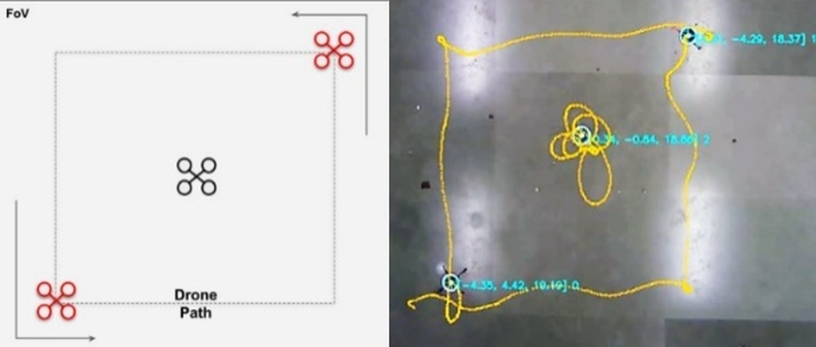
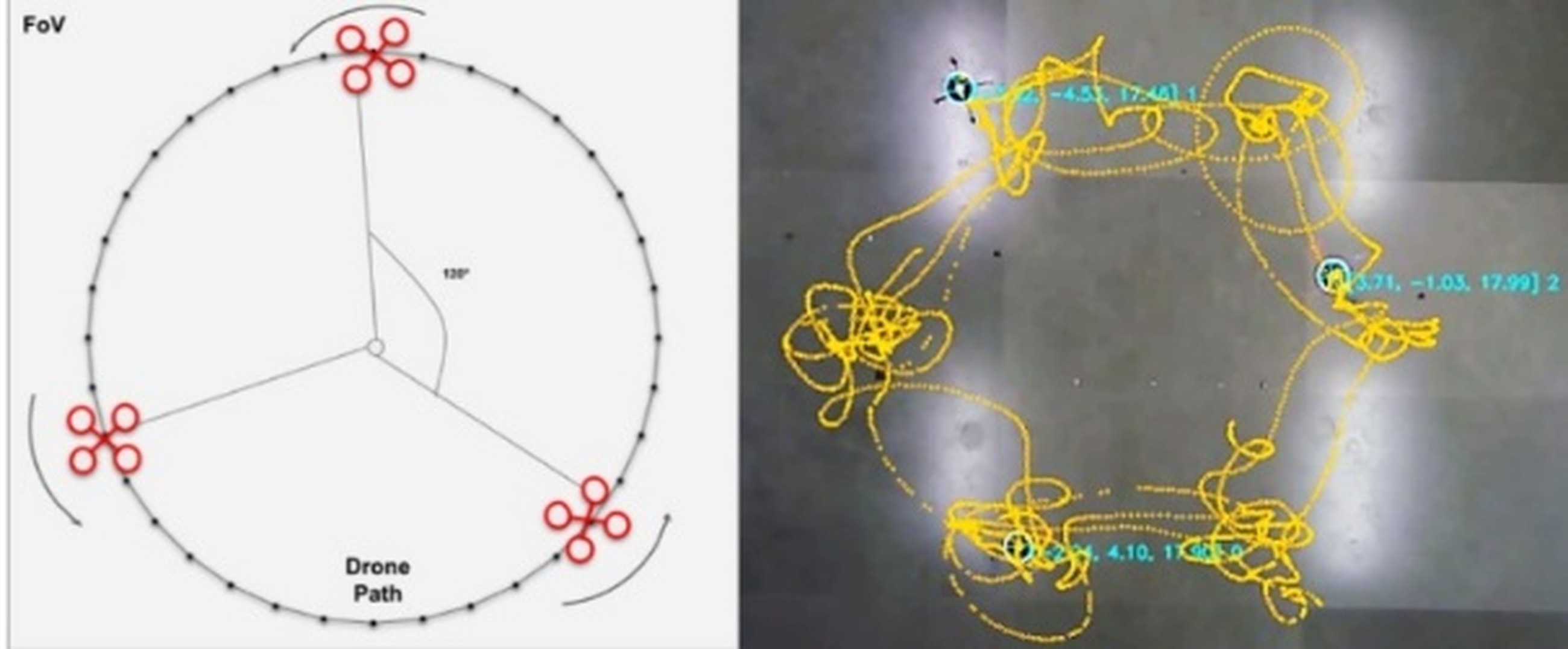
To achieve the desired formations, this paper describes the methodology used to update the target coordinates of each drone. This involves taking feedback from the drones’ positions within FoV. By continuously monitoring and analyzing the relative positions of the drones, adjustments to the target coordinates are made to ensure that the desired formation is maintained. In order to evaluate our multi-drone control, circular & square traversal, and synchronized circular three-drone formation were implemented using three drones as shown in Fig. 15.
Square traversal by three NAVs
Circular traversal by three NAVs
Fig. 15. Traversal of different shapes by NAVs
Circular traversal: The set point of the drone is changed continuously by shifting every 10° to create an arc. The drone completes a circular trajectory in 36 set point coordinates. The arc coordinates are at 10°, and the difference is calculated as shown in Equation 6, where a ranges from 0 to 36 and r is the circle radius. dist_apart and wc_id are formation control variables set to zero for circular traversal.
Square traversal: This traversal is implemented by calculating the vertices of a square of a predefined size. Two drones opposite each other traverse the vertices to form a square. As shown in Fig. 15a, one drone holds its position at the center.
Rotation formation: Rotation by three drones is achieved in the same way as circular traversal. However, a 120° arc is created for each drone as shown in Fig. 15b. The new coordinates are calculated as shown in Equation 6 by setting dist_apart to 120° and wc_id (Whycon ID) as 0, 1, 2 for our rotation formation.
Latency
The different factors that cause latency in the multi-drone control system are calculated and presented in Tab. 3. The brief description of calculated latency is as follows.
Tab. 3
Overall latency in multi-drone control system
Case | Latency (in ms) |
Camera frame capture | 8.33 |
Marker detection | 12 |
Drone identification | 27 |
PID loop | 100 |
MSP packet | 190 |
Communication | 4 |
Total | 341.33 |
Marker detection latency: The image is processed using the WhyCon package to detect the markers in the frame. The package uses the OpenCV library to detect the marker using the flood fill algorithm. It takes an average of 12 milliseconds to detect the marker and determine the relative coordinates of the marker within the frame.
Latency in drone identification: Every drone has the same pattern of markers; hence, it is challenging to keep track of individual drones when they hover around within the FoV. The initial position of the drone is fixed in the frame. The previous position of the drone is saved in every iteration to calculate the nearest previous position to determine the current positions of the drones. It takes 27 milliseconds to calculate the positions of each drone.
Feedback control loop latency: Parallel PID is used to control the drone’s ϕ, θ, ψ, and throttle. The feedback control loop for each drone takes 100 milliseconds.
Command packet latency: After calculating ϕ, θ, ψ, and throttle by a feedback control loop, this data is converted to an MSP packet for sending through the network. The firmware on the drone receives the MSP packet and decodes it according to the MSP protocol. The conversion from raw data to MSP packet takes 190 milliseconds.
Latency in communication: The communication medium is wireless, and the topology used is star network, i.e., MSPpackets first go to the router and then routed to the drone. Hence, the communication latency is 4 milliseconds.
Thread scheduling latency: Every thread has some clock assigned by the scheduling algorithm. The frequency of the time slot assigned to a thread depends on the number of threads running and each thread’s requirement and priority. Hence, the latency due to each process can vary due to thread scheduling. Variance in latency in the feedback control thread is directly proportional to scheduling.
Challenges faced
Differentiating between the drone ID was overcome by comparing the markers’ current position with the previous position of the marker. Individual threads were implemented for the PID control of each drone, along with tuned PID constants of the drone within that thread. The most daunting challenge faced was the scheduling of threads. An operating system assigns time slots to different threads according to available resources. This creates an issue as control threads’ calculation must be done in real-time. This problem can be solved by using a real-time operating system or by decreasing the number of threads such that the threads get time slots frequently.
Conclusions
This paper presents a localization approach to control the NAV in an indoor environment using a monocular camera. This approach allows controlling the NAV in four degrees of freedom with a maximum latency of approximately 0.341 seconds and an average localization error of 3.1 cm. The package developed for communicating between NAVs and ROS systems ensures minimum latency for control commands. Multiple parallel proportional-integral-derivative controllers helped to stabilize the drone in the custom-controlled environment. The applications developed on the proposed techniques show the various possibilities suitable for a low-cost academic environment. Autonomous path planning indicates an affordable and accurate means to traverse the drone while avoiding obstacles. Landing of NAV on a moving platform and multi-drone control demonstrates the scope to use numerous components in our approach. We can even establish this localization system in an indoor environment like a warehouse to automate various robotic systems like drones and differential drive robots. In the future, we plan to scale the system with multiple monocular cameras to expand the controlled environment.