
Introduction
Solidification is the process of change of phase from liquid to solid when the temperature of the liquid is brought below its freezing point; thereby converting the liquid metal into solid form [1]. Since the energy of the liquid is less than that of solid above the melting point, the liquid phase is more stable above the melting point. Subsequently the energy of liquid becomes more than that of solid below the melting point and this solidification process of stabilization makes solid phase more stable than liquid below the melting point [2].
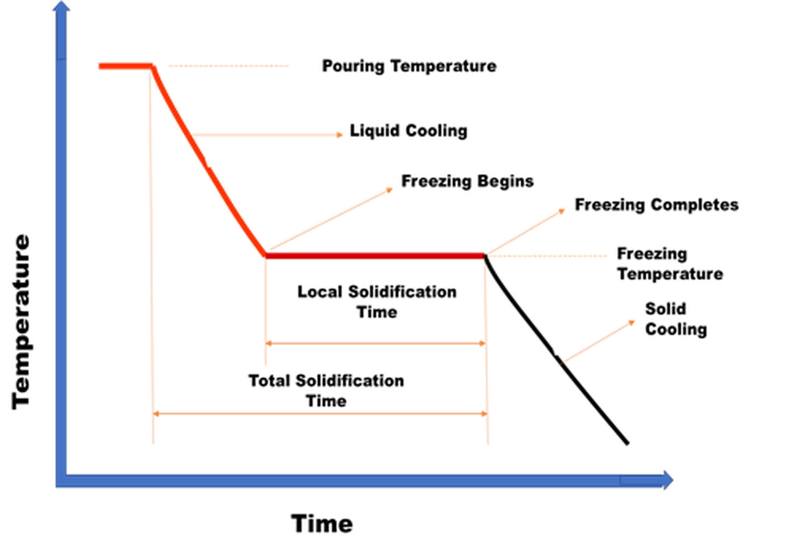
The cooling curve of pure metal and of pure Iron are shown in Figure 1 and 2 respectively and a sharp cooling from liquid to solid phase is observed in pure iron [3] and it can be inferred from Figure 1 and 2 that the grain morphology depends on the temperature gradient in liquid phase and can be controlled by optimizing the composition, nucleation and growth rate of solid phase [4-5].

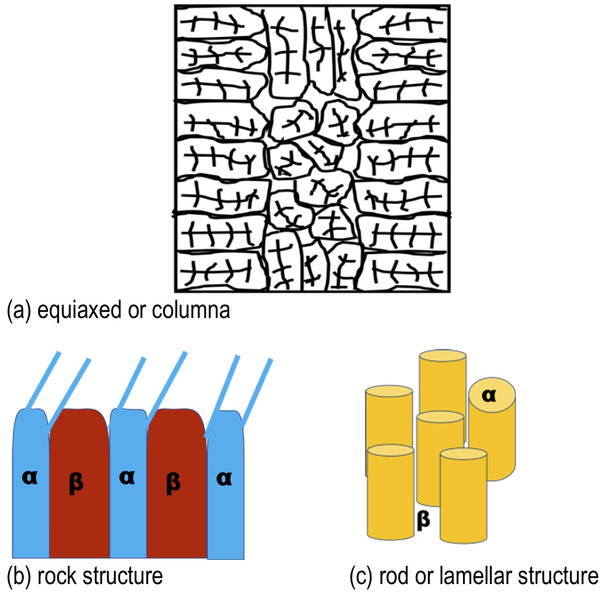
Thermodynamically, solidification in casting is the process of transfer of heat through radiation, conduction via direct contact with the mould, and convection via air gap between mould and ingot [3]. Predominantly, the grain structure under solidification [5] is found to be equiaxed or columnar if it is a single phase structure (see Figure 3a), rock structure (see Figure 3b) and rod or lamellar structure if it is eutectic (see Figure 3c). However, under typical solidification settings, the cast section displays an irregular grain structure as thicker sections solidify at slower cooling rates with a smaller thermal gradient and consequently have coarser microstructure than thinner sections [6]. Fine equiaxed microstructure throughout the cast parts is advantageous since effective feeding of the molten metal in the mushy zone leads to homogeneously dispersed porosity, minimized hot tearing susceptibility and better mechanical properties [6-7].
Researchers have predominantly used directional, progressive, inoculation and rapid solidification methods [4-7]. In order to minimize the shrinkage defects, the area that is far away from Sprue (the pouring point) has to be cooled first followed by the solidification towards the riser. This helps in continuous supply of molten metal from the risers to eliminate defects caused due to shrinkage voids while freezing. This technique of solidifying the molten metal starting from the sprue to the mould cavity and then to the riser is known as directional solidification [8]. In contrast, progressive solidification begins from the walls of casting and progresses perpendicularly from that surface. Inoculation is the process of adding a material in a small amount to molten metal/ alloy in order to modify the solidification process with an effect on grain nucleation. Moreover, the microstructure, mechanical properties and defects may be conveniently controlled by specific inoculants and inoculation practice [7]. Rapid solidification involves the rapid removal of thermal energy constituting superheat and latent when transiting from liquid phase at elevated temperature to solid phase at ambient temperature. In contrast to smaller degrees generated in conventional casting, even before the solidification begins, the rapid heat removal can induce an under-cooling up to or above 100° C. A rapid cooling process achieves a cooling rate larger than 104 K/s albeit a cooling rate of 103K/s produces rapidly solidified microstructure. The contact-time at elevated temperature is restricted to be less than 10-6 s after which rapid quenching is done at ambient temperature. The type of quenching medium determines the rate of solidification and microstructure [6].
Researchers have proposed various modifications to the above mentioned techniques by optimizing the solidification process parameters, to develop a higher thermal gradient, reduce defects and improve the grain structure. Motivated by this huge metallographic potential, the present paper aims to present a cogent assessment of the state of the art solidification techniques that control grain structure by systematically reviewing 65 research articles. Then a keyword co-occurrence network (KCON) analysis is developed to visualize the predominantly researched areas and future research directions in solidification techniques domain.
The rest of the paper is arranged as following: Section 2 details the methodology adopted for the systematic literature review (SLR) in this work. Section 3 briefs various solidification techniques predominantly studied to improve the grain structure. A comprehensive review of solidification process parameters influencing the microstructure and the mechanical performances are also detailed in Section 3. The network analyses depicting the future research directions are presented in Section 4 and conclusions are given in Section 5.
Methodology
Following the SLR methodology proposed by Rajagopal et al. [9], the articles for review are selected from the Web of Science database using the keywords “casting”, “foundry”, “solidification”, “progressive”, “directional” and “inoculation”. 33,173 papers that were published in total during 2010–2024 were gathered and examined. Short messages and letters to editors are screened out of this initial sample. Then, after reviewing each paper's title, abstract, and keywords for relevance, 65 papers dealing with the solidification techniques were determined to be appropriate for the study. These 65 papers were segregated into four categories addressing directional, inoculation, progressive and rapid solidification domains respectively and a comprehensive review detailing each domain is presented in the below sections.
. SOLIDIFICATION TECHNIQUES TO CONTROL GRAIN STRUCTURE
. Directional Solidification (DS)
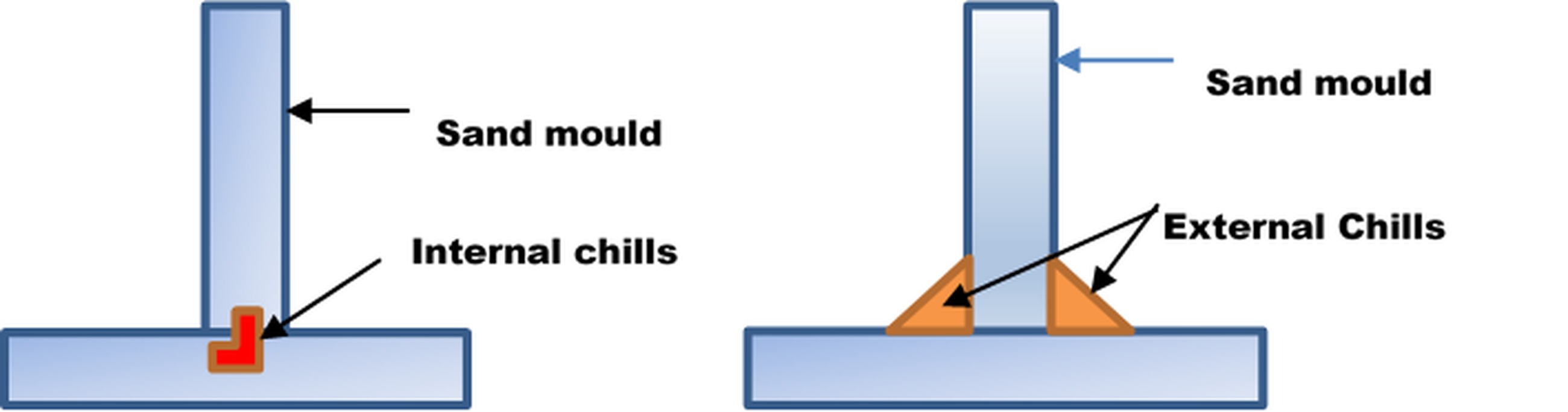
In DS, the cooling originates from the bottom and progresses to the top of the mould and this controlled process of feeding molten metal into a temperature controlled-mould is achieved by (i) using Chvorinov’s rule to design the riser system (ii) using internal or external chills. The internal chills (see Figure 4(a)) are small metal parts placed inside the cavity of the mould before pouring molten metal. This enables the solidification of the molten metal around the cavity first. The internal chill should have a chemical composition similar to the molten metal poured. External chills (see Figure 4(b)) are metal inserts in the walls of the mould cavity that can remove heat from molten metal more rapidly in order to promote directional solidification. In addition to usage of external chills, Nakajima [8] proposed the usage of the molten metal in which pressurized gas atmosphere of nitrogen, hydrogen and oxygen is dissolved to produce lotus (porous) cast metals and alloys. In lotus metal, longitudinal cylindrical pores converge in one direction, resulting in better mechanical characteristics than porous and foamed metals manufactured by powder metallurgy and other methods.
In the subsections 3.1.1., three such DS techniques for producing lotus metal (mould casting, continuous zone melting casting and continuous casting [8]) were briefed. Further, the conventional DS techniques and a comprehensive review on the advanced DS methods reported by recent researchers are addressed in subsections 3.1.2- 3.1.8.
. Lotus metal fabricating DS techniques
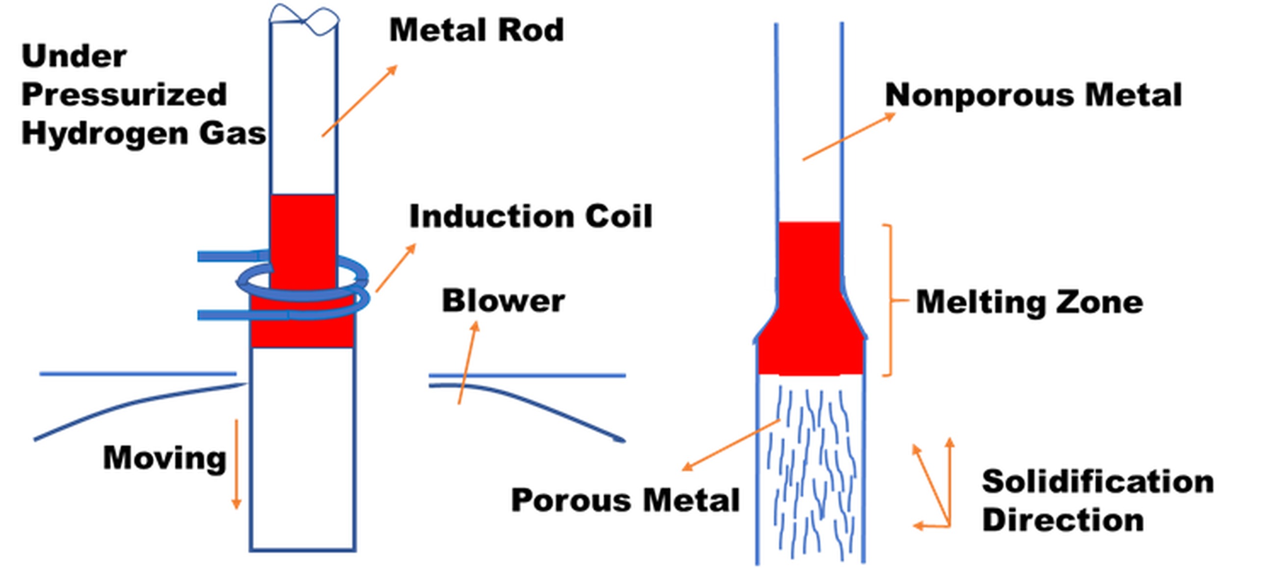
In mould casting process, the metal is melted by an induction furnace under a high-pressure gas atmosphere as shown in Figure 5.
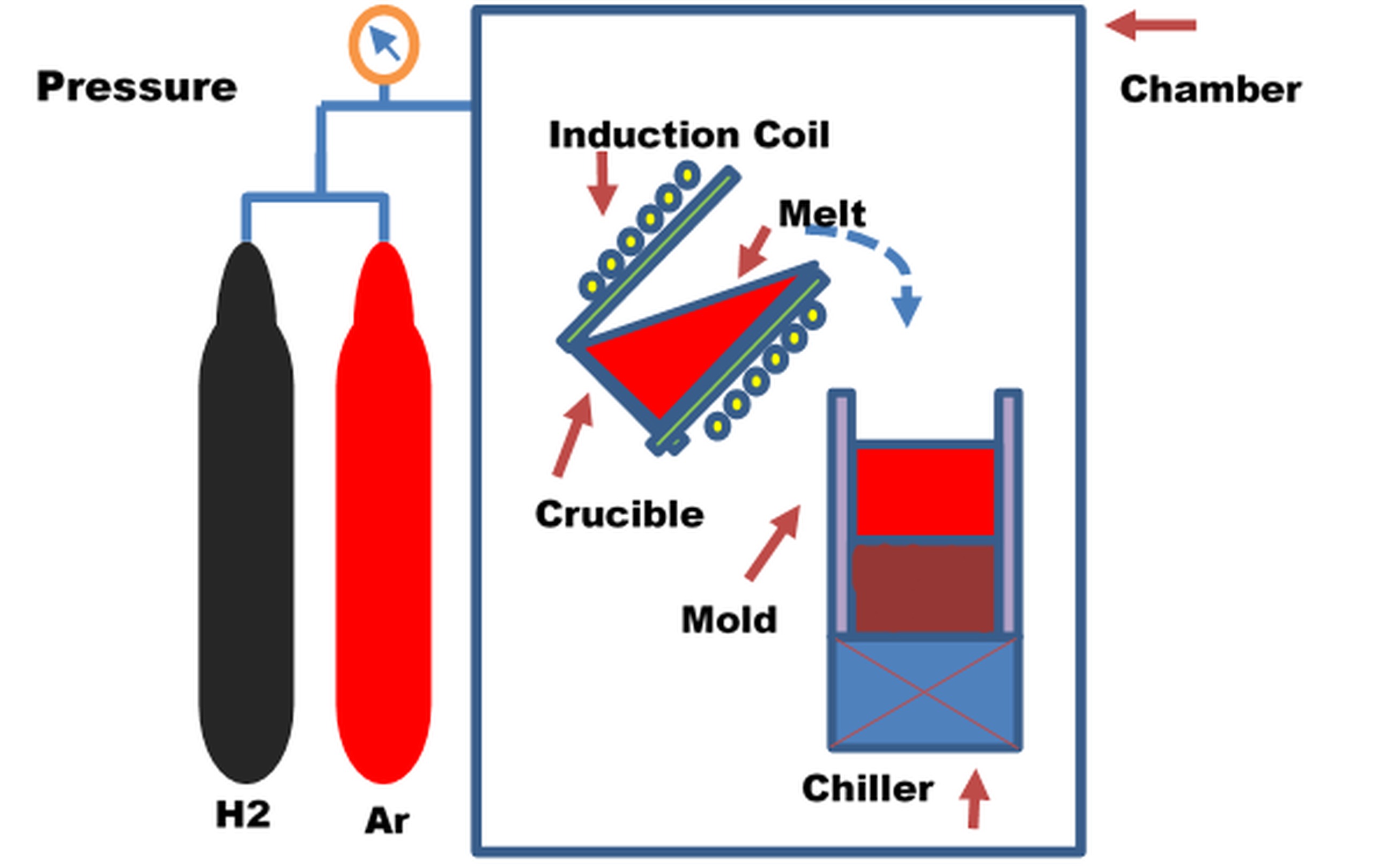
As per Sieverts’ law, the gas is dissipated into the molten metal till it reaches the equilibrium gas concentration under pressure, and the saturated melt is poured into the mould [8]. To solidify the melt uni-directionally, the mould is cooled by a chiller or circulated water leading to the formation of the elongated pores and the evolution/growth of these pores can be controlled by moving the cooling part. The process parameters used to control the grain structure in this technique are the melt temperature, type of dissolving gas, solidification rate and gas pressure. However, in case of metals and alloys with low thermal conductivities cooling becomes slower at top region since water-cooled plate is used at the bottom of the mould, resulting in coarser pores. In order to rectify this, a continuous zone melting process is developed. Here, part of the specimen rod is melted by induction heating to absorb the dissolving gases and concurrently, the specimen rod is moved downward at a given transfer velocity and the solidification occurs simultaneously in the lower part of the melt zone, thereby yielding a constant pore size (see Figure 6). This transfer velocity is the controlling process parameter in continuous zone melting technique.
The described mould casting and continuous zone melting techniques are not suitable for mass production and hence continuous casting (see Figure 7) is developed for fabricating long ingots.
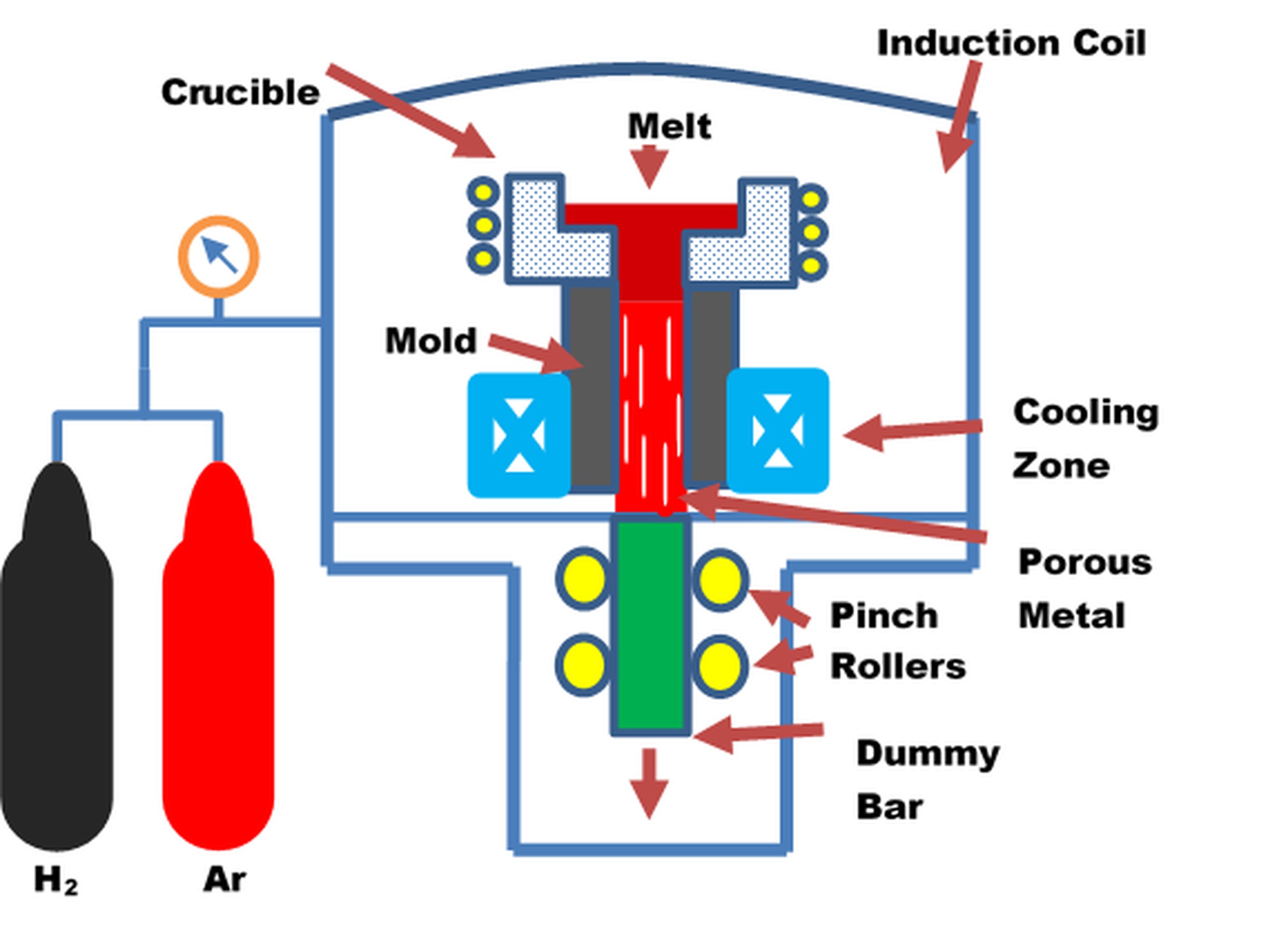
Here, radio-frequency induction heating in a high-pressure mixture gas is used to melt the metal in a crucible. The liquid metal is subsequently drawn downwards and solidified concurrently through the cooled mould at a predetermined transfer velocity, resulting in an anisotropic behaviour with superior mechanical properties due to the stress concentration being perpendicular to the loading direction [8].
In order to develop a higher thermal gradient and reduce defects, different DS techniques such as Bridgman process, liquid metal cooling (LMC), high rate solidification (HRS), horizontal directional solidification method (HDSM), downward directional solidification process (DWSP) and gas cooling casting (GCC) are reported in literature [10, 11].
. Bridgman process
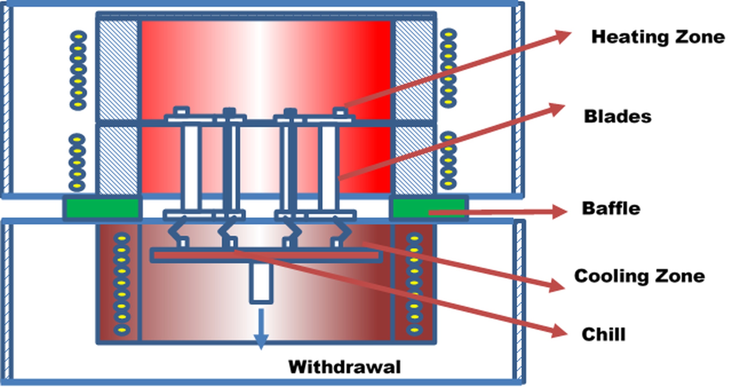
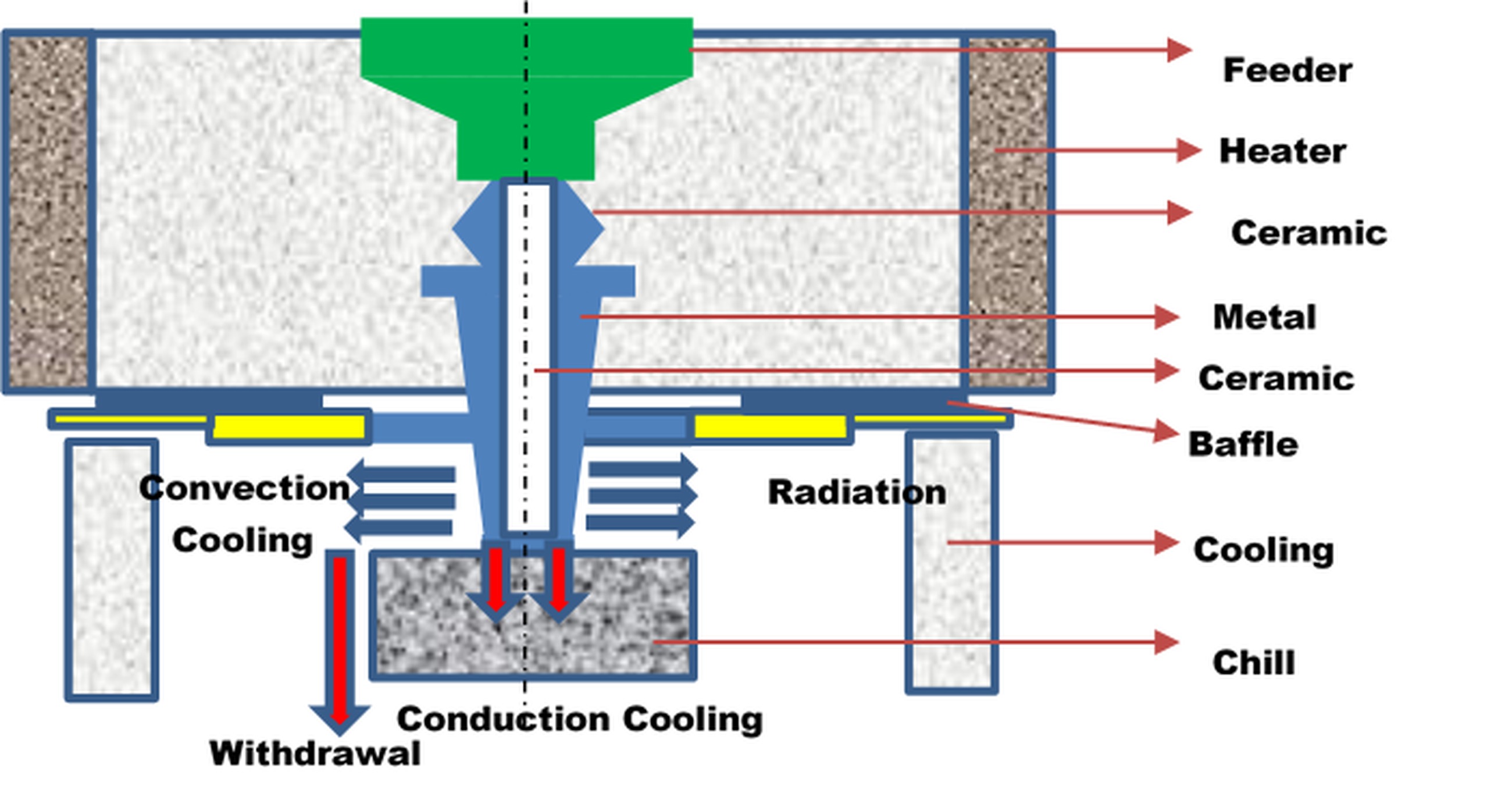
The conventional Bridgman process [10] includes a furnace containing five components: heating zone, Baffler, Cooling zone, Chill, and Withdrawal unit, as shown in Figure 8. Here, the alloy is poured to ceramic mould after melting through vacuum chamber. In order to produce vertical temperature gradient, the mould is mounted on a copper chill and the complete setup is withdrawn from melting chamber to cooling chamber promoting vertical temperature gradient in the mushy zone of casting. A positive thermal gradient is produced at solidification front by separating the heating and cooling zone by a thermal baffle. The withdrawal rate, pouring temperature, heating temperature and holding time are the process parameters that determine the dendritic microstructure and grain morphology. Bridgman process is predominantly used in fabrication of Ni based turbine blades.
. High rate solidification technique
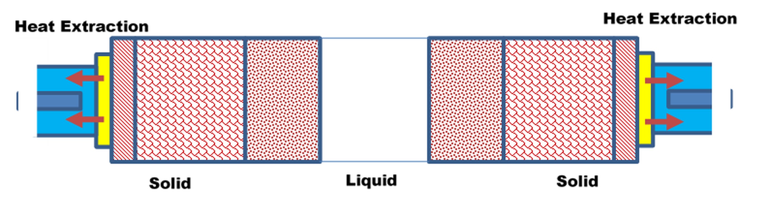
If the Cooling zone in the Bridgman furnace is equipped with water-cooled copper rings, then the process is called HRS technology (see Figure 9), by which super alloy casting is produced by DS method.
. Horizontal directional solidification method
Similarly, instead of an enclosed ampoule Bridgman furnace, if a flat-bottomed crucible with short sidewalls is used, then this variant of Bridgman process is known as horizontal directional solidification method (HDSM) (See Figure 10). This technique is predominantly used in growing various large oxide crystals including Yb: YAG and sapphire crystals [3].
. Liquid metal cooling (LMC) technique
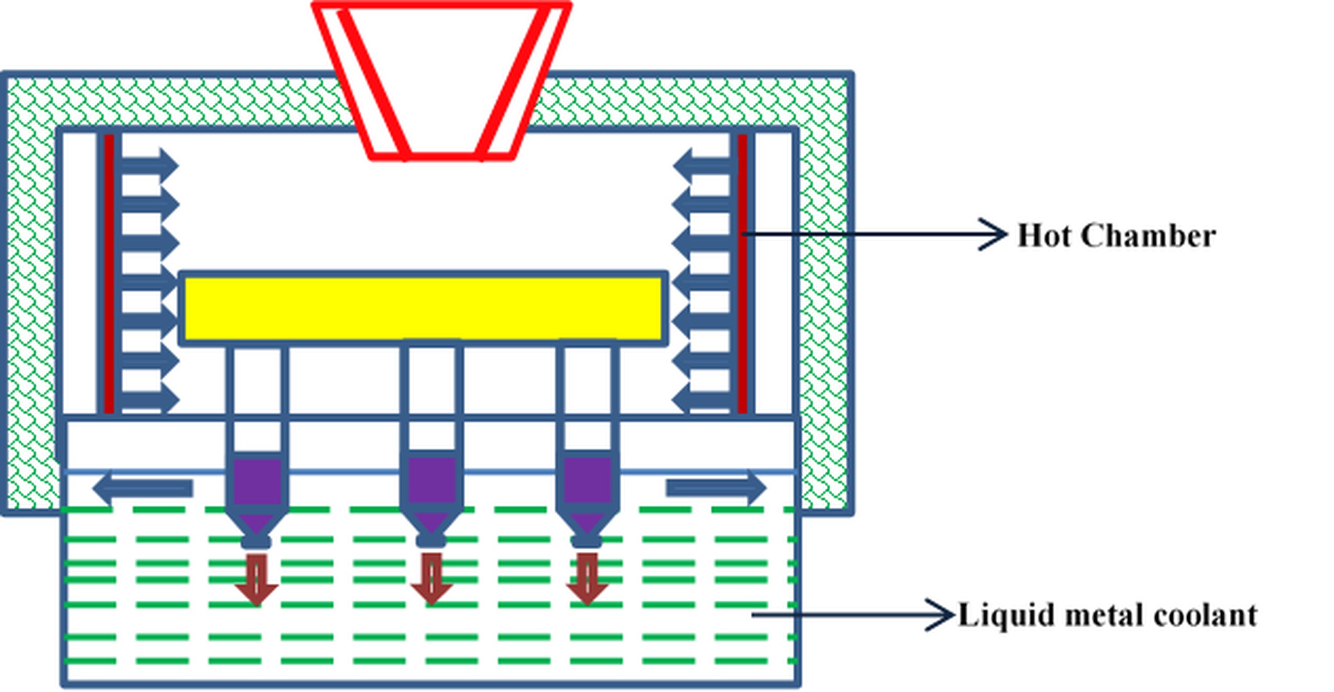
In LMC (see Figure 11), the bottom of castings is cooled by a water brass jacket, the upper part of the mould is kept in hot chamber and the lower part is kept in the melt of liquid metal coolant (Al) at a temperature 700°C. LMC provides high thermal gradient and withdrawal rate by conductive heat transfer during solidification process [12].
. Gas cooling casting process
In the Gas Cooling Casting process (GCC), in addition to the radiation cooling observed in Bridgman process, the mould surface undergoes an impingement cooling by the inert gas, injected at high velocity directly below the furnace baffle (see Figure 12). Using high velocity gas flow and heat transfer due to radiation heat in outer surface is removed in GCC.
However, LMC and GCC processes cannot be effectively used in turbine blades casting applications due to the thick and non-uniform shell molds and the possibility of the cooling gas permeating the furnace chamber and leading to a reduction of the furnace temperature and the emergence of disoriented grains respectively.
. Downward directional solidification process
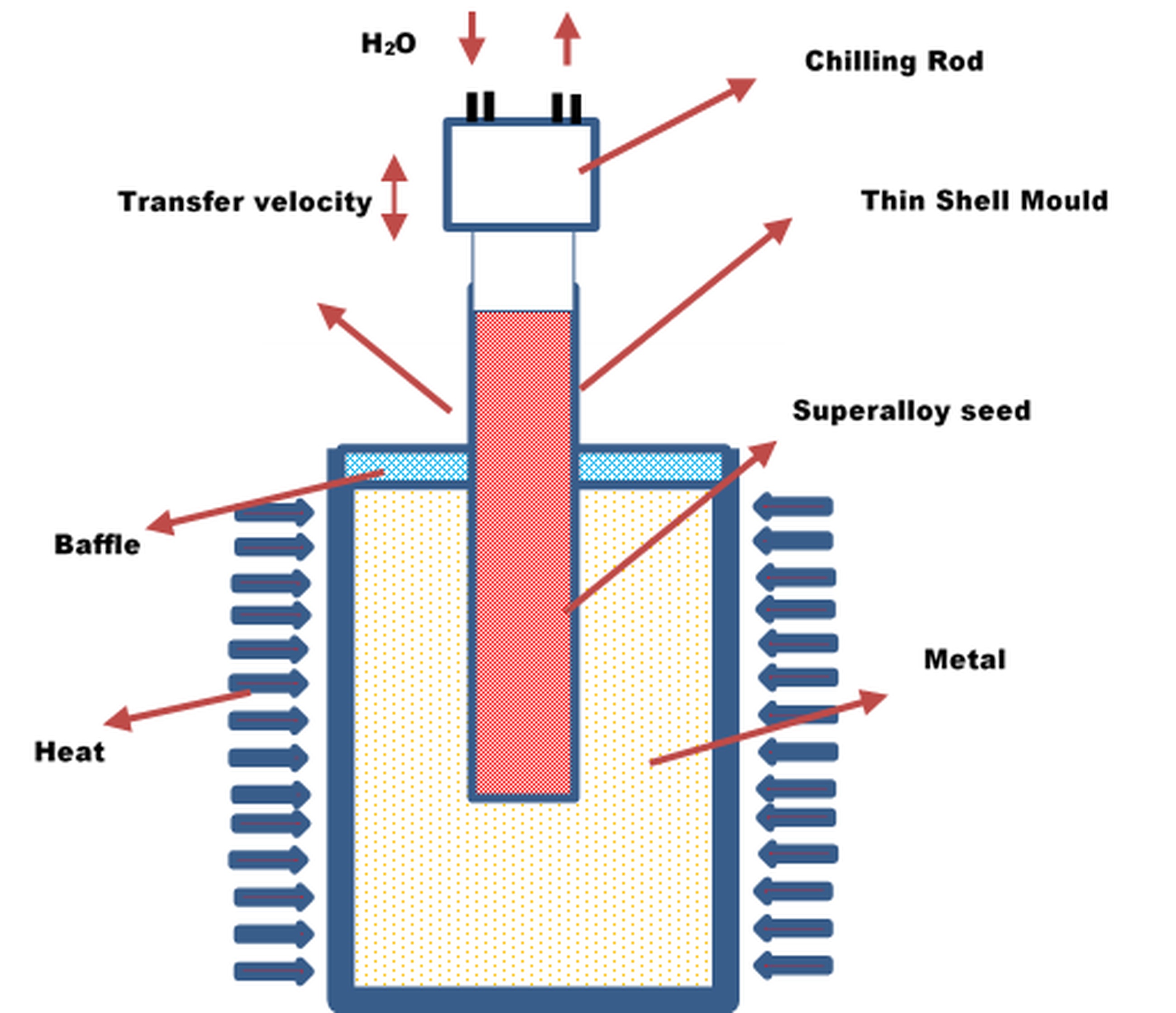
To overcome the difficulties of these DS processes, Downward Directional Solidification process (DWDS) was developed [12] which can produce a very high thermal gradient (see Figure 13). The ceramic molds used in this process are much thinner (1 mm) than those in the other DS processes (7 mm). Freckles in superalloy blades are reduced due to suppression of density inversion during downward growth [10].
. Comprehensive review on advanced DS techniques
Balter et al. [13] developed a variant of Bridgman furnace equipped with thermally insulating aerogels as a crucible material for solidification of alloys having alloying components with varying density. High cooling rates under microgravity condition are obtained by drastic increase in solidification velocity with movable cooling rod. This sets up a convection free grain growth resulting in complete diffusive solidification state without the negative influence of fluid-flow or macro-segregation. The columnar grain and dendrite growth in super alloy casting are simulated by Zhang and Xu [14] using interpolation of macro thermal transfer based on modified shape function dendrite model coupled with the cellular automaton-finite difference (CA-FD) method. This modified macro simulation model is used in the prediction of dendrites distribution and morphology in large scale Bridgman casting production.
Ghedjati et al. [15] investigated the Bridgman process and determined that the increase in pulling velocity increases density of α-phase dendritic and decrease inter dendritic distance. Under lower pulling velocity condition, the dendrites are aligned with pulling direction; whereas for large pulling velocity, the dendrites growth initiates first in cooling direction then becomes broken and coarsened. Hardness value was found to be co-related proportionally to pulling velocity. Ma et al. [16] determined that freckles in Bridgman DS process, formed due to chemistry of alloy and geometric factors, were found to exist in casting regions with positive curvature and were absent in negative curvature surface. Compared to thermal conditions, controlled geometric features were found to reduce freckles in Bridgman DS process. Freckles were predominantly formed both on the surface and core of mushy zone [17].
Zhang et al. [18] simulated HRS process for fabrication of single crystal super alloy blade samples to determine the optimal withdrawal rate by modelling the width and temperature difference input parameters of mushy zone at the cast-mold interface using cellular automaton finite difference method. The model was validated with experimental data and was found to be easier to modify and adapt for a consistent and stray-grain free directional solidification technique. The buoyancy force caused by density variation of liquid metal was found to produce freckles.
Saad et al. [19] proposed a numerical analysis of HDSM for the formation of channel segregation using the three-dimensional cellular automaton —finite element model to avoid freckles. The nucleation and microstructure growth is integrated in the proposed model by kinetic laws. The process parameters-vertical temperature gradient, cooling rate and lateral temperature gradient significantly influence the formation of segregation defects.
Wang et al. [20] examined the microstructural characteristics as a function of the withdrawal rate for the single crystal CMSX-6 super alloy prepared using DWSP. In comparison with Bridgman process, DWSP exhibits 7 times better thermal gradients and is an excellent candidate for single crystal solidification as this process decreases eutectic pool size, minimizes microspores, refines precipitates and microstructure. They also advocated that the increase in withdrawal rate in the DWSP decreases the primary and secondary dendrite arm spacing along with γ′ phase in the dendrite and inter dendritic regions. The withdrawal rates do not have any effect on the difference in the shape of the γ/γ′ eutectic. Experimental investigations on solidification of a ternary alloy in upward direction at a constant temperature gradient under different growth rates in a Bridgman-type directional solidification furnace showed that the Primary and secondary dendritic arm spacings and micro hardness decrease and increases respectively with an increase in crystal growth rate.
Costa et al. [21] predicted the primary and tertiary arm dendrite lengths in terms of HDSM process parameters: growth rates, local solidification time and cooling rate. The HDSM experiments were carried out under transient heat extraction with cooling rates varying from 0.90 C/s to 220 C/s and the dendrite lengths were measured by optical microscopy and metallography. The non-planar solidification front resulting in several defects is caused by irregular shape of cast in DS. Lian et al. [22] demonstrated through simulation that this phenomenon can be prevented by varying the wall thickness to control the circumferential temperature gradient. The directional dendrite morphology and growth were simulated by Zhang and Xu [23] with pouring temperature and withdrawal rate as parameters. Based on heat transfer and solute diffusion, 3D dendrites growth model was built in macro and micro scale. The dendrite orientation mathematical project and temperature interpolation algorithm were used as messenger between macro DS process and micro dendrite growth.
Wang et al. [24] proposed a multi-shell mold structure and water-immersion cooling method (MSMWI) for the DS of castings and found that MSMWI was 5.8 times faster than air natural cooling, and the temperature gradient was increased by 78 times. Durga et al. [25] formulated a highly parallelized mesoscale solidification model based on a cellular automaton method coupled with a macroscale process model to predict grain structure during DS for simple geometry. Modelling solidification phenomena across nano- to macroscopic scale by massive phase field computations or multiscale approaches shows the potential for the simulation of real processes such as additive manufacturing, single crystal casting, welding or advanced solidification processes [26].
Huang and LiLin [27] presented the future researches with transparent model materials processed using DS under three aspects: 1) accurate measurement of material properties and alloy phase diagrams in more plastic crystals, especially to find more transparent eutectic and peritectic alloys; 2) accurate measurement of the grain boundary groove shape to obtain precise data of the anisotropy parameters of the interfacial free energy in transparent model materials; 3) to get clear pictures of DS processes with morphology details in a relatively large area, with continuous movement of liquid and particles, to give experimental support to numerical simulations aiming at accurate description of microstructure formation during solidification of multicomponent alloys under complex conditions of real casting and welding processes.
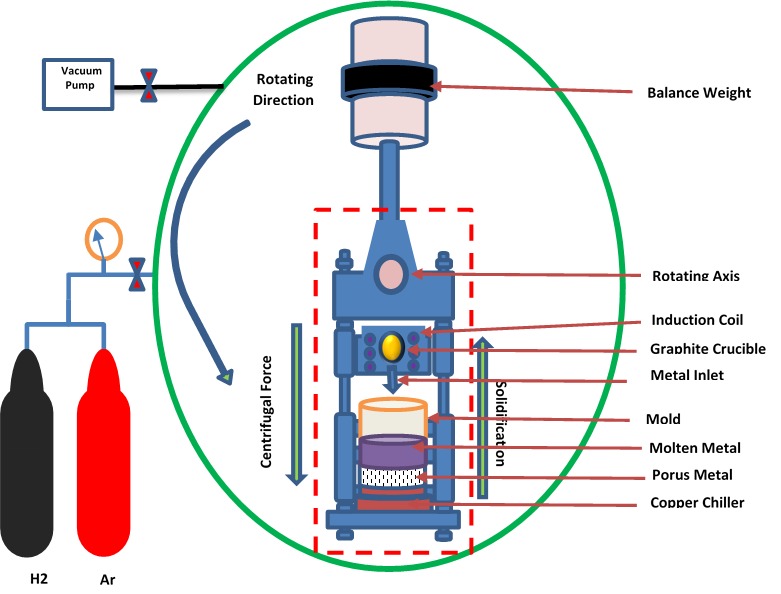
Kim et al. [28] advocated that compared to the conventional DS techniques such as mold casting, zone melting, continuous casting and Bridgman method, centrifugal casting resulted in higher porosity and elevated mean pore diameter in the fabricated lotus-type porous copper. The centrifugal casting experimental setup (shown in Figure 14) consists of a graphite crucible, a mould which facilitates DS through a copper plate chiller, an induction coil, an electric motor that facilitates the revolution of mould, a vacuum pump, and a gas line [28].
The alloy was melted by an induction coil under pressurized hydrogen gas and a pyrometer tracks the temperature of the molten alloy. When the molten metal is heated beyond its liquidus temperature, the temperature is held constant for 5minutes and later directionally solidified in the mould by the action of centrifugal force generated through the application of an electric motor rotating at a constant velocity. Higher the distance from bottom of ingot and rotational velocity, higher the mean pore diameter. The porosity is significantly influenced by the applied centrifugal pressure on liquid/solid interface which increases with the rotational velocity and reduces with increasing distance from bottom of ingot.
Li et al. [29] proposed that in consideration with the geometry structure of turbine guide and the casting defects predominantly observed under gravity pouring condition (i.e. misrun of vane exhaust edge and coarse columnar grains of vane body), the centrifugal casting process can be deemed suitable for enhancing the filling quality of molten alloy into the mould with narrow cavity because of the centrifugal force. The centrifugally casted nickel-based superalloy turbine guide was experimentally found to be defect-free when compared with that fabricated under gravity pouring condition.
Similar to centrifugal casting, the counter gravity casting is an advanced process, in which the alloy melt is driven against gravity into mould under pressure differential or electromagnetic force followed by DS under pressure. The resulting DS have flat isotherms in absence of forced melt flow during the casting operation [30].
Yang et al. [30] developed a new DS technique (shown in Figure15) for the fabrication of TiAl castings by combining induction skull melting, counter-gravity casting, and mold heating processes resulting in a controlled filling and grain growth.
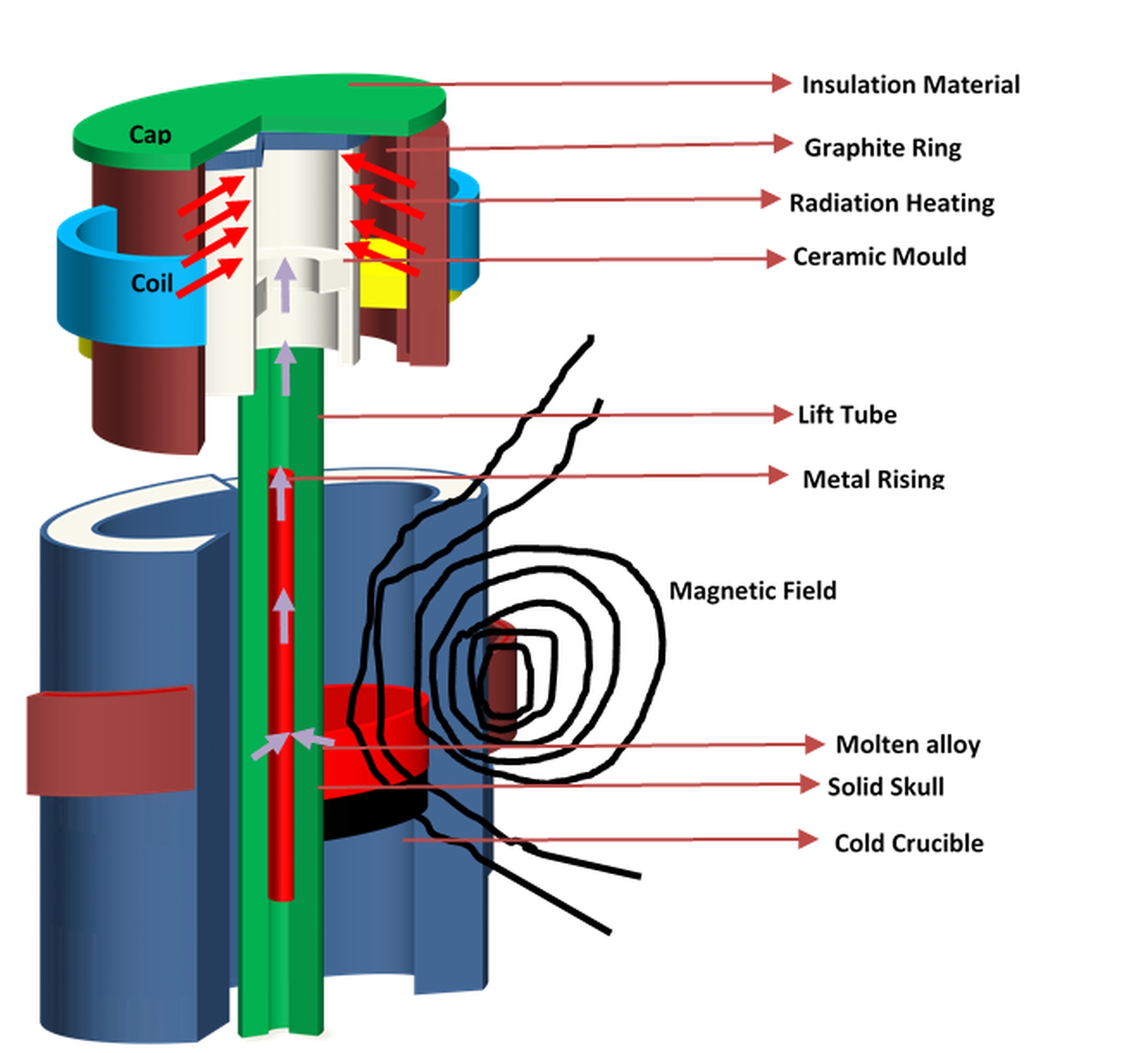
The experimental set-up consists of a vacuum-sealed, water-cooled, double-layered stainless steel furnace with top and bottom compartments linked together by a flange. The bottom compartment consists of a lift tube crucible that melts the sample specimen and the upper compartment consists of the ceramic mould. A vacuum pump and pressure controller monitor the pressure in the furnace. Under pressure, the melted sample rises against gravity in the lift tube and fills the ceramic mould. An induction coil heats the graphite ring surrounding the mould thereby elevating the temperature of the inner mould. The melt then directionally solidified and the cast is removed from the top compartment. The X-ray examination of the component fabricated using this advanced technique did not reveal any macro-defects thereby show casting the superiority of this method [30].
. Inoculation
The inoculation materials are normally made of a FeSi-alloy doped with different elements to guarantee a modified solidification process with an effect on nucleation. In particular, inoculation of a steel with chemically active elements (Ca, Al, REM) accompanied by de-oxidation has found wide application in the casting production. This process refines the grains by 2 – 3 numbers, lowers the depth of transcrystallization and increases somewhat the strength characteristics. A similar effect is observed upon the introduction of carbide-forming elements (V, B, Ti, Zr, Nb) or nitride or carbonitride compounds into the composition. Conventionally, four inoculation practices namely- in-mould inoculation treatment, ladle inoculation, self-inoculation method (SIM) and electrical pulses inoculation are reported.
. In-mould inoculation
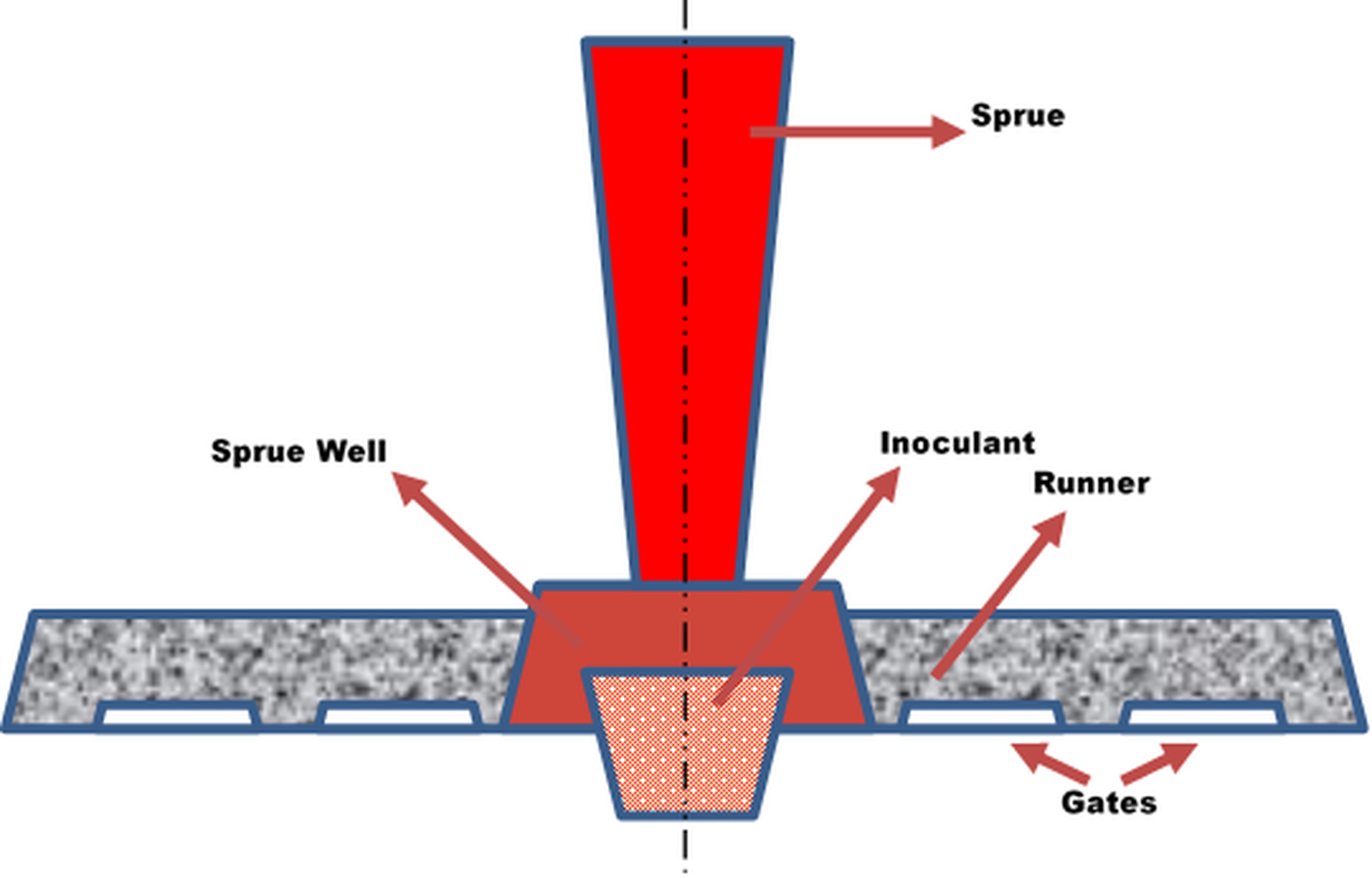
In in-mould inoculation treatment, the inoculants are included as a preformed insert placed in the pouring basin of a mould (see Figure 16) or as granulated inoculant placed in the gating system.
. Ladle inoculation
In ladle inoculation the parent metal is inoculated by adding inoculant to the metal when the melt is transferred from the furnace to the pouring ladle. The turbulence quickly dissolves the inoculant and evenly disperses it throughout the molten bath.
. Self inoculation
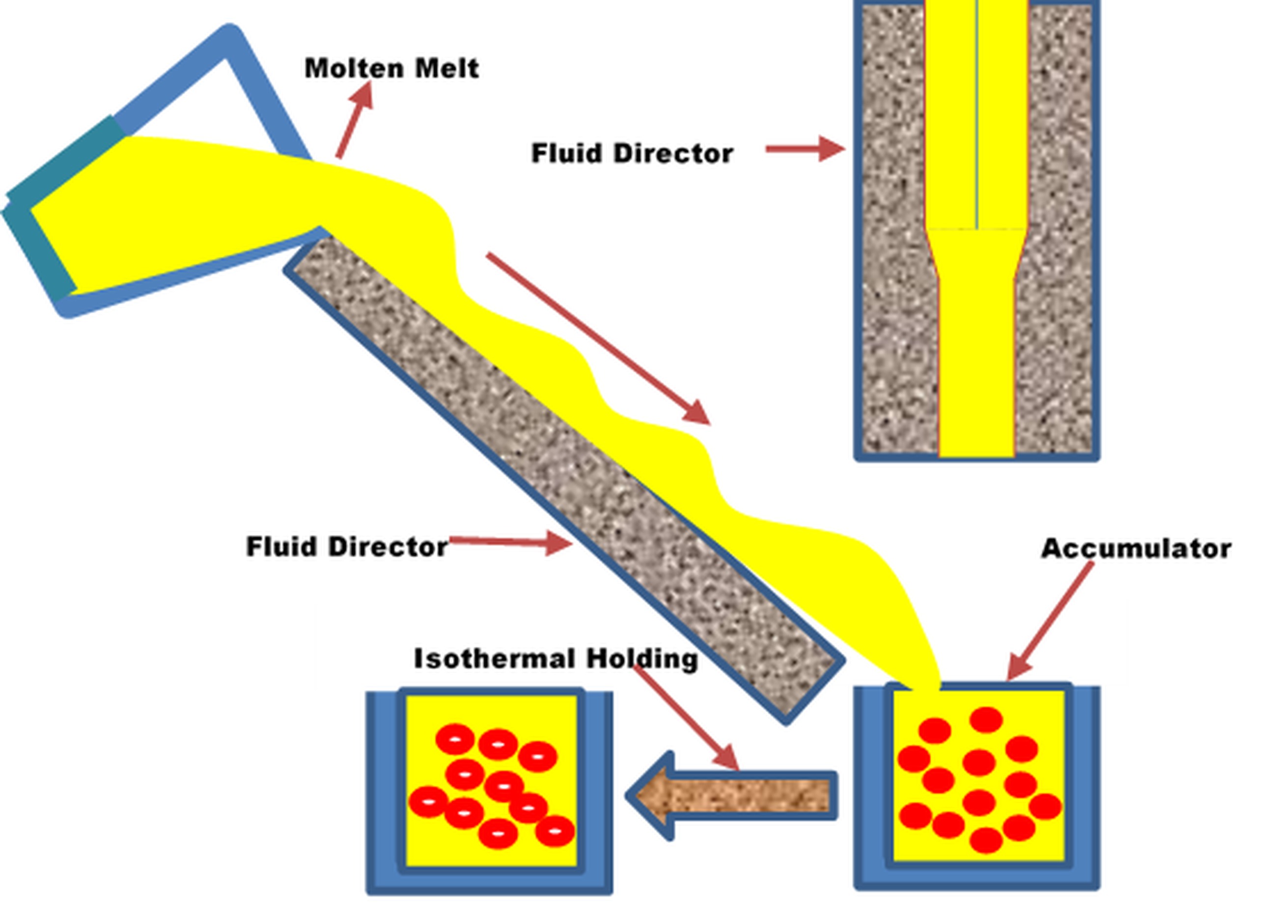
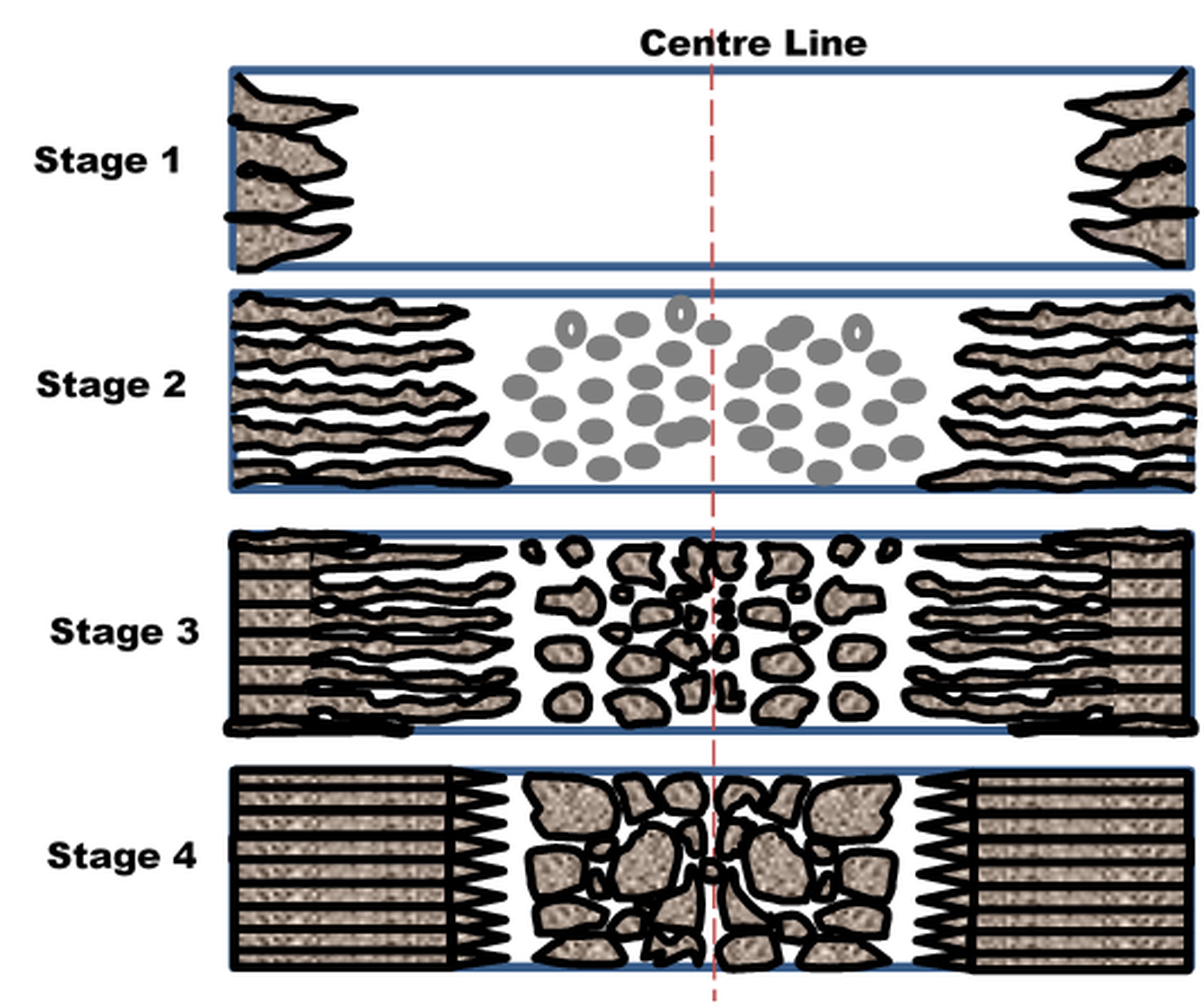
The self-inoculation method (SIM) is a type of solidification structure control method predominantly used in semi-solid metal processing. The process (see Figure 17) involves mixing liquid alloy with the solid alloy of the same composition (self-inoculants), and subsequently pouring the melt into a mold (accumulator) through a multi-stream fluid director. The resulting semi-solid slurry is then held isothermally for a certain time, and then directly poured into cold water to obtain water quenched specimens. The prepared slurry is then subjected to the rheo-diecasting process to obtain the near-net shape. Heterogeneous nucleation is enhanced due to the addition of self-inoculants (primary inoculation), and large amounts of chilled grains and dendrite fragments are formed in the melt due to the chilling and shearing of the cooling channel (secondary inoculation), resulting in high grain density and small grain size in solidification structure.
. Electrical pulses inoculation
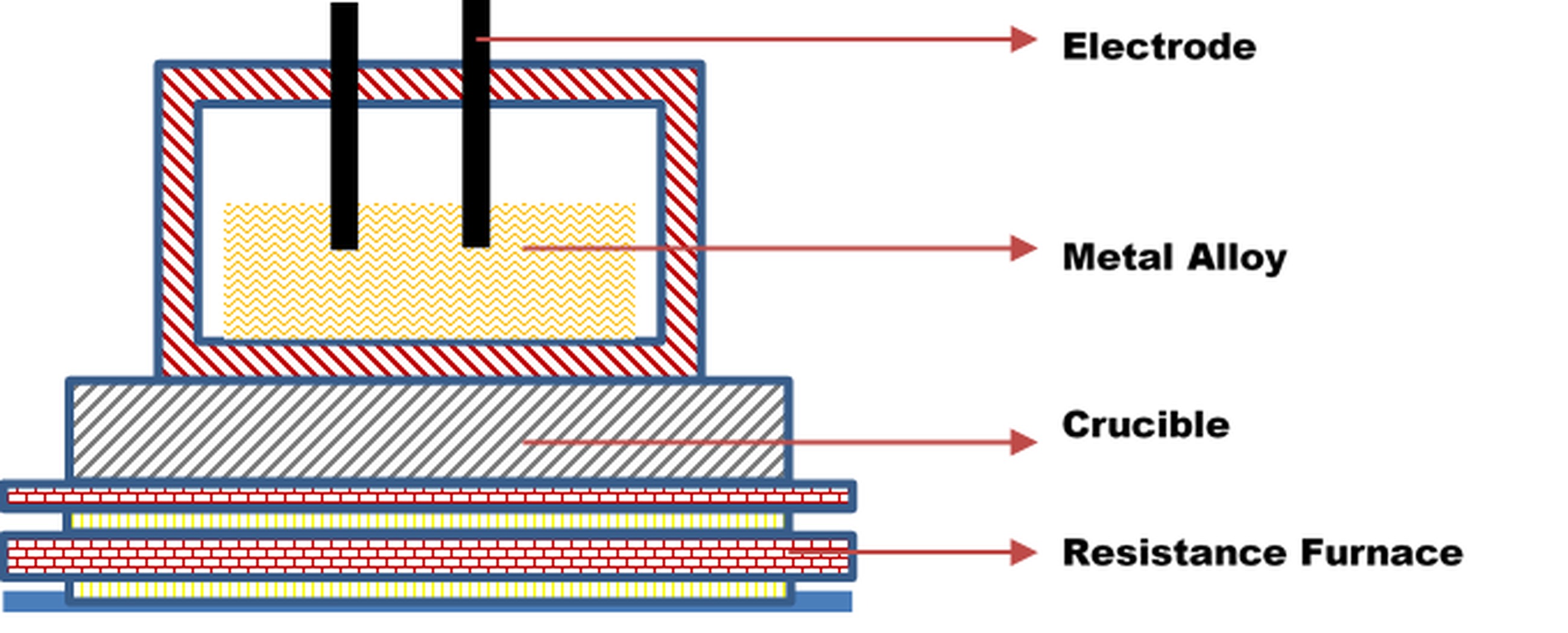
The electrical pulses inoculation setup consists of (1) a resistance furnace where the temperature will be accurately maintained by the intelligent temperature controller (2) a crucible containing the molten metal (3) Electrodes. Once the metal alloy is melted in the crucible within the furnace, the inoculant is added. At the same time the electrodes are immersed in the molten metal and electric pulse current is switched on. Then the crucible with the molten alloy is taken out of furnace and allowed to cool (see Figure 18).
. Comprehensive review on advanced inoculation techniques
Borsato et al. [31] studied the effect of the inoculants: Si, Al, Ca, RE and Bi on the fatigue resistance of pearlitic ductile iron and found that the fatigue resistance is mainly influenced by micro-shrinkage porosities close to specimens' surface that act as crack initiation points, by the microstructure defects such as low graphite nodule count and graphite degeneration and by the inoculants added. Borsato et al. [32] through metallographic analysis observed that the increase in nodular count decrease the sizes of micro-shrinkage cavities.
Rashidi et al. [33] and Alabbasian et al. [34] subjected Ductile Ni-Resist (DNR) cast alloy with different manganese content to in-mould inoculation treatment with various inoculation (Si) percentages and differing casting modulus respectively. Increased inoculation and casting modulus resulted in decreased carbide formation leading to improved tensile and yield strength and decreased hardness. Moreover, inoculation led to uniform distribution of graphite resulting in a lower corrosion rates. In-mould inoculation process thus improved the mechanical properties of the alloy and satisfies the corrosion resistance criteria required for corrosive environment.
Rathi et al. [35] studied the effect of mould temperature and inoculant (Al-5Ti-1B) in the fabrication of Al-7Si-3Cu alloys by integrating permanent mould casting process and in-mould inoculation. The inoculation treatment resulted in a finer equiaxed structure. Higher mould temperature reduced hot tear susceptibility of the alloy by refilling the material in later stage of solidification.
Pongen et al. [36] studied the effect of Al-3.5 Ti-1.5C and Al-3Cobalt as grain refiner added to A713 alloy through ladle inoculation method. Tensile strength and hardness increased with addition of grain refiners. With different composition of grain refiners, coarser grain, finer grain and equiaxed grains were obtained. Santhosh et al. [37] studied the ladle inoculation treatment of ductile iron casting and demonstrated that inoculant (Fe-Si-Mg alloy) is the most significant factor affecting the casting quality with a contribution percentage of 44% and an increase in inoculation results in a significant improvement in acceptance percentage of ductile iron castings. Bo et al. [38] showed that self-inoculation in Magnesium alloy produces smaller grains with globular shaped crystal. The process parameters- pouring temperature, amount of self-inoculant added, and the slope angle of multi-stream mixing cooling channel significantly influenced the microstructure of partially re-melted billet, average size of the solid particles and the shape factor.
Xing et al. [39] developed a novel rheo-casting process coupled with self-inoculation method (SIM), for the microstructure control of semisolid wrought alloy. The primary phase with dendritic morphology in the conventionally cast AZ31 alloy has readily transformed into near spherical one in the slurry produced by SIM from melt treatment temperature between 690 °C and 710 °C and self-inoculants addition of 3%−7%. Achievement of the non-dendritic microstructure at the higher melt treatment temperature requires increased self-inoculants addition or decreased slope angle of fluid director. The increased holding time leads to decrease of shape factor albeit coarsening of particle size.
Similarly, Li et al. [40] and Li et al. [41] studied the fabrication of ZA27 alloy and A356 aluminum alloy respectively prepared by rheo-die castings with Self Inoculation Method. Li et al. [40] determined that the dendritic microstructure of ZA27 alloy obtained from SIM to be significantly superior than that formed from permanent mold and produced fine spherical microstructures. In thin-walled rheo-diecasting, isothermal holding time process parameter had significant effect on primary α-Al particles (α1), albeit little effect on the microstructure of secondary solidification. Li et al. [41] observed that the liquid phase segregation occurs during rheo-diecasting process of semisolid slurry and the primary particles (α1) show obvious plastic deformation in the area of high stress and low cooling rate. The amount of dendrite fragments decreases with the increase of filling distance. The low cooling rate in the first filling positions leads to coarse eutectic structures, while the high cooling rate in the post filling positions promotes small and compact eutectic structures.
Ming et al. [42] observed that in SIM-Rheocasting process, the nucleation is expected to take place in the entire remaining molten liquid when the remaining liquid fills the die cavity, and the secondary solidification particles (α2) are formed after the process of stable growth, unstable growth and merging. Tan et al. [43] investigated the selective laser melting additive process coupled with inoculation treatment by adding Ti nanoparticles to 2024 aluminium and found the new process to be capable of substantially eliminating the anisotropy, hot-tearing cracks and columnar structure, and refining the grains. Fay [44] correlated the machinability of inoculated Grey Cast Iron with the metallographic characteristics. This study also illustrated the importance of the ratio Mn/S to guarantee the presence of manganese sulfides in the matrix, beneficial for iron machinability. Komarov et al. [45] studied the effect of inoculation with surface active elements (Te, Bi, Sb), chemically active elements (Al, Ti) or carbide-forming elements (B) known as complex inoculation on the macro- and micro-structure of low-carbon steel. It is shown that complex inoculation can prevent trans-crystallization and refine the microstructure in castings. The trans-crystallization is removed upon growth in the number of crystallization centers in the zone of concentration super-cooling
Sun et al. [46] studied the effect of electrical impulse inoculation on the as-cast structure of 7075 aluminum alloy. It is found that through inoculation treatment, the number of the secondary branch crystal of the solidification structure is effectively controlled achieving equiaxial and spherical grains. To prevent the segregation of alloying elements during casting of 100Cr6 (high carbon chromium bearing steel), Cerium was added [47] to form dispersoids that act as inoculants to facilitate the formation of equiaxed but not columnar grains. By adding Cerium, the equiaxed grains became finer and the segregation diminished considerably. As a result, the rolling contact fatigue life of the steel was improved markedly [47]. Austempering process gives equivalent or superior quality Austempered Ductile Iron engineering component compared to those manufactured from other ferrous as well as non-ferrous material. The effect of inoculation treatment coupled with austempering revealed that the addition of S , Mn, & P had significant effect on the microstructure with fabrication of the spherical structure of Carbon (Graphitization) [48].
Sahoo et al. [49] reviewed the role of different additives on sand mould composition and different trace elements or inoculants on mechanical properties and microstructure of sand casting. The paper also highlights the application of artificial intelligence techniques in predicting the sand mould quality and further optimizing the casting process parameters. This article then analyses the potentials and feasibility of three-dimensional printing in sand casting process. Fraś et al. [50] studied the effect of the solidification processing and alloy chemistry on the chilling tendency index (CT) of wedge-shaped castings made of cast iron The experimental investigation revealed that the graphite nucleation coefficients, the eutectic cell growth coefficient, and the critical cooling rate for the development of eutectic cementite are functions of the cast iron chemistry and time after inoculation. Further, increasing the Mn and S inoculant contents, as well as the time after inoculation lowers the critical cooling rate, thus increasing the chilling tendency of the cast iron. In contrast, C, Si and P increase the critical cooling rate, and as a result, they reduce the cast iron CT and chill.
. Progressive Solidification
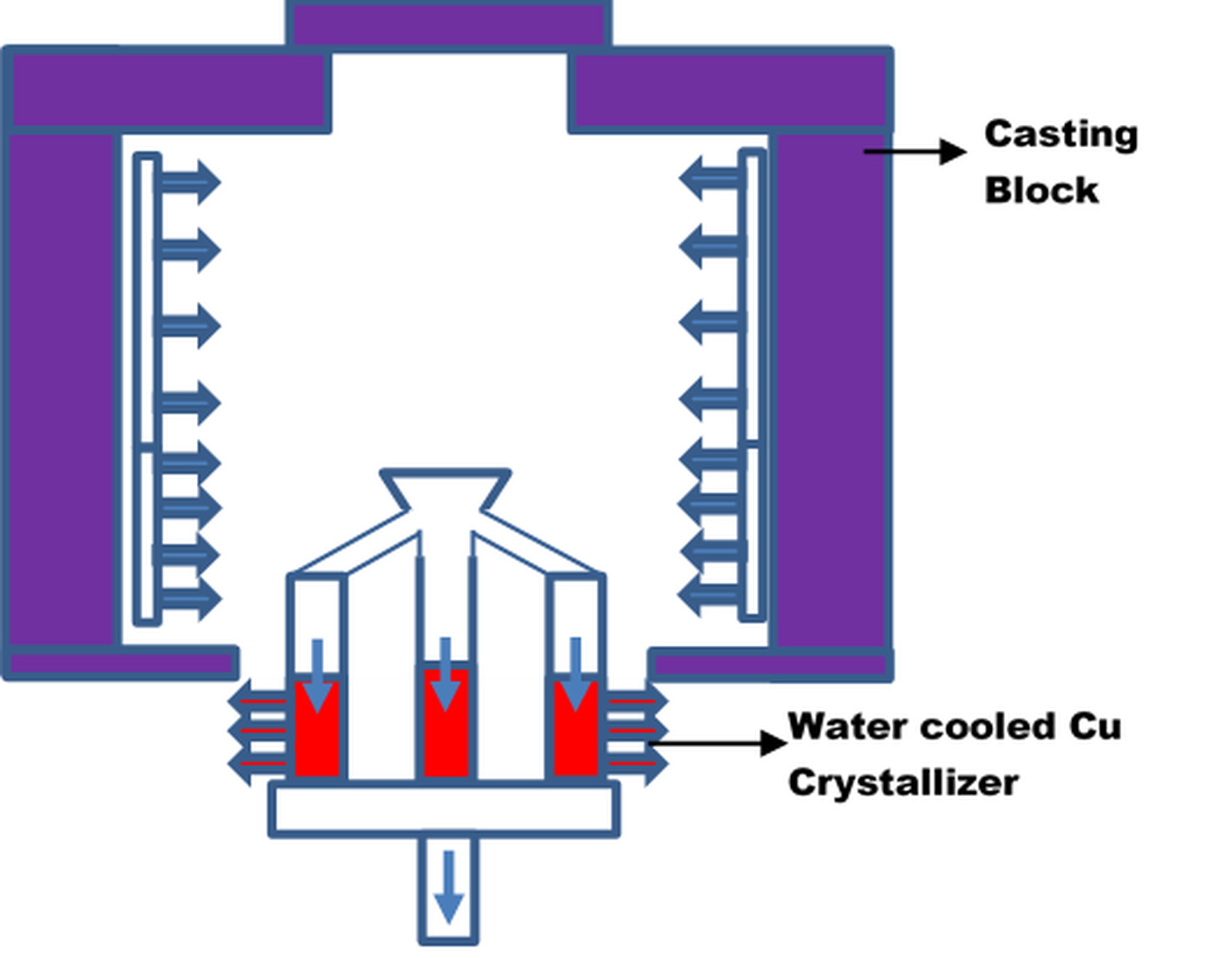
In progressive solidification (see Figure 19), the solidification starts from outer sides of the casting, and progresses perpendicular to the surface and move towards the casting center. The recent advances in progressive solidification techniques are detailed in the sub-section 3.3.1.
. Comprehensive review on advances in Progressive Solidification
Kilbride et al. [51] observed that two solidification processes (network and progressive solidification) dominated the water–ice phase transition required in bio-medical preservation applications. Network solidification has been typically observed in small sample cryo-straws or cryo-vials. Progressive solidification is more often observed in larger volumes or environmental freezing. These different ice phase progressions have a significant impact on cryopreservation in scale-up and larger volume cryo-banking protocols, thereby necessitating their study under cell therapy applications.
Mackay & Sokolowski [52] studied the formation of micro-shrinkage porosity in progressive solidification of wedge casted Al–Si–Cu alloys having different Si and Cu concentrations, with cooling rates ranging from 0.75 down to 0.0450Cs-1. Based on interpretative thermal analysis with fraction solid calculation, the requirements for the lowest level of porosity were found to be primary α-Al dendritic mass being low in volume and more in permeability, a high volume of Al–Si eutectic phase albeit within a shorter freezing range, and a low volume fraction of the Cu and Mg containing phases post Al–Si eutectic reactions.
Wang et al. [53] observed that the electromagnetic continuous casting (EMCC) technique can produce progressive solidification of the high-Nb TiAl alloy, eliminating shrinkage and porosity, and generates obvious grain refining effect. As compared with the raw as-cast alloy, the obtained EMCC alloy presented a much finer microstructure with lamellar colonies of about 50-70μm mean size. This fine morphology is due to the electromagnetic stirring which broke the initial dendrites and enhanced the heterogeneous nucleation.
Choudhari et al. [54] demonstrated through simulation that proper feeding aids in getting the hot spot completely shifted inside the feeder. Meena & El Mansori [55] investigated the simulation analysis of simultaneous mold filling and progressive solidification of ductile iron casting in a permanent mold. The thermal analysis revealed the variation in the nature of alloy for different solidification curves. This is because of the variations in true eutectic point and carbon equivalent of the melt. There is a significant decrease in the overall heat transfer coefficient with time during the solidification process. Two distinct zones (center and outer) were observed on the produced samples based on the average graphite nodule counts and average graphite nodule size. Ayar et al. [56] simulated the behavior of metal filling and progressive solidification of Aluminum alloy AlSi5Cu3 under sand casting process using AUTOCAST software. Through simulation, the optimal gating and feeding system designs were determined to minimize the casting defects. Similarly, Saravanan et al. [57] investigated the effect of feeding distance on the progressive solidification behavior of bar-shaped ductile iron sand castings and found that solidification is a function of the geometric modulus. Yigezu et al. [58] reviewed the progressive solidification techniques for the fabrication of particulate reinforced metal matrix composites through the stir casting route. Various processing challenges, such as undesirable interfacial reactions, porosity, uneven distribution, agglomeration, engulfment, and poor wettability are addressed.
. Rapid Solidification (RS)
Researchers have studied three methods to induce rapid solidification:
ensuring an elevated level of undercooling before solidification;
ensuring a higher level of transfer velocity during continuous solidification;
ensuring a rapid cooling rate during solidification.
The first concept, which minimizes the likelihood of heterogeneous nucleation by eradicating the crucible-initiated-nucleation and segmentation of heterogeneous nucleants from the melt, is achieved through (a) the droplet emulsion (DE) technique (b) the gas atomization technique and (c) magnetic levitation.
. Droplet emulsion
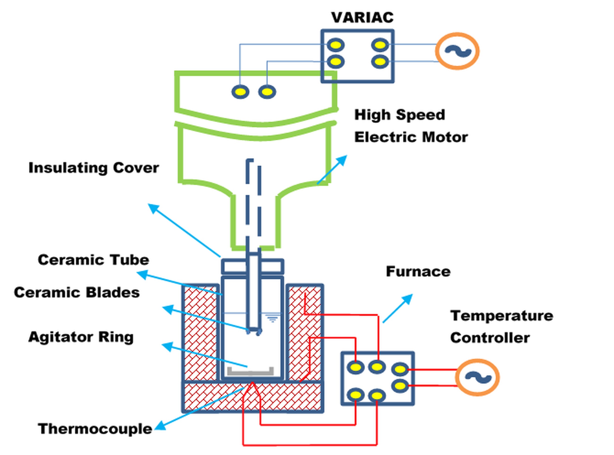
In DE technique shown in Figure 20, fine droplets are produced by melting of a small volume of the sample in an inert carrier fluid and stirring the immiscible fluids at an elevated rate by electrically powered ceramic blades. A significant quantity of fine droplets produced during stirring might be extremely under-cooled through extraction of heat by thermocouple surrounding the furnace.
. Gas atomization
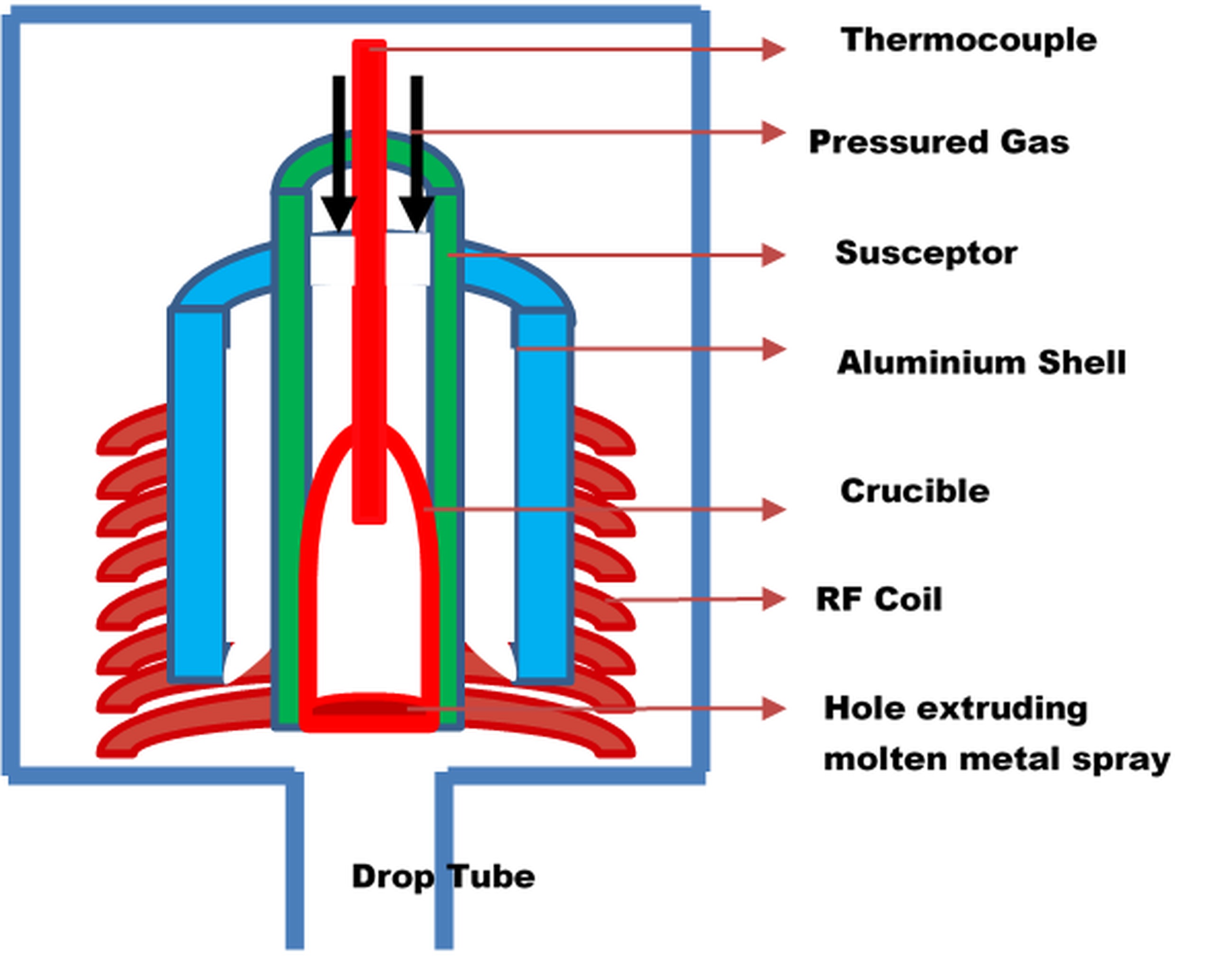
In drop tube or gas atomization technique (see Figure 21), a fine dispersion of droplets is formed when a high-energy fluid (gas or liquid) impacts the molten metal. First, the sample alloy in the evacuated crucible is heated by induction in a protective atmospheric condition. When the required temperature is reached, the pressurized nitrogen gas is injected into the molten. Later, when the temperature of the assembly falls to ambient, the rapidly solidified particles get accumulated at the end of the drop tube.
. Magnetic levitation
In magnetic levitation (see Figure 22), a freely suspended drop with no contact with any medium is generated using levitation techniques. The levitation coil together with the solid metal rod is placed inside ultrahigh-vacuum chamber backfilled with He or He–H2 gases.
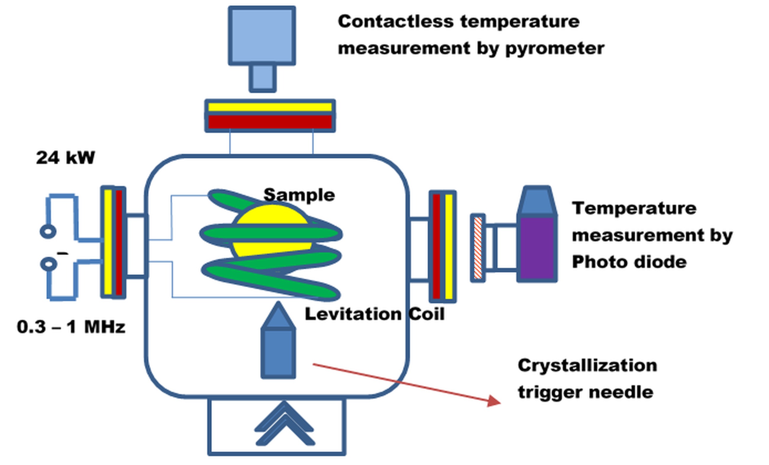
The levitation is achieved only by enhancing the electrical conductivity of the solid specimen. The specimen is heated through conduction by the eddy currents produced by the enveloping levitation coil, thereby levitating the sample. The pyrometer monitors the temperature of the specimen. An external crystallization trigger needle then induces the solidification of the undercooled molten metal.
. Continuous rapid solidification
Under second approach named as Continuous rapid solidification (CRS), an elevated transfer velocity is imposed during continuous solidification. This is achieved by extracting an adequately thin sample at elevated velocity through a temperature gradient that is steep enough to restrict the solidification front from advancing the drawing velocity. A variant of CRS is Eletro-slag re-melting CRS in which the as-cast sample serves as a consumable electrode (see Figure 23). Electric current (especially Alternating Current) is transmitted between the electrode and the new ingot, fabricated in the base of a water-cooled copper mold. The new ingot is coated in an engineered slag superheated by the electric current.
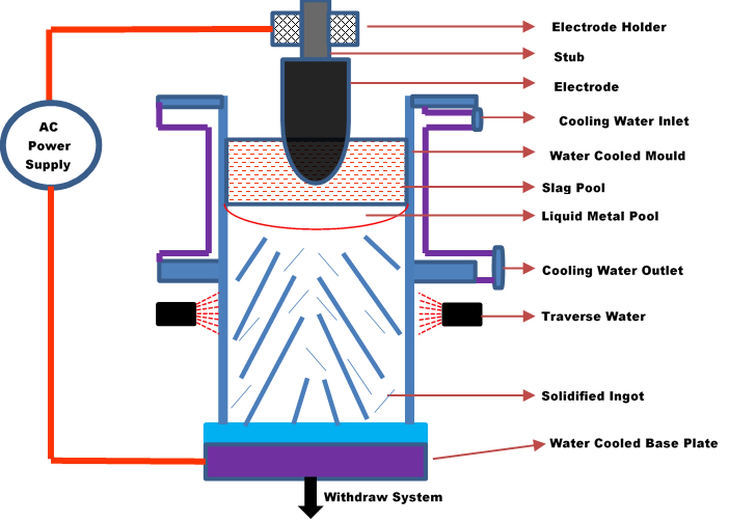
The tip of the electrode is gradually fused by interaction with the slag. These droplets move through the slag to the base of the water-cooled mold and gradually freeze as the ingot is rapidly solidified upwards from the base of the mold. As the alloy solidifies, the slag pool constantly glides above the refined alloy.
. Chill block melt spinning process
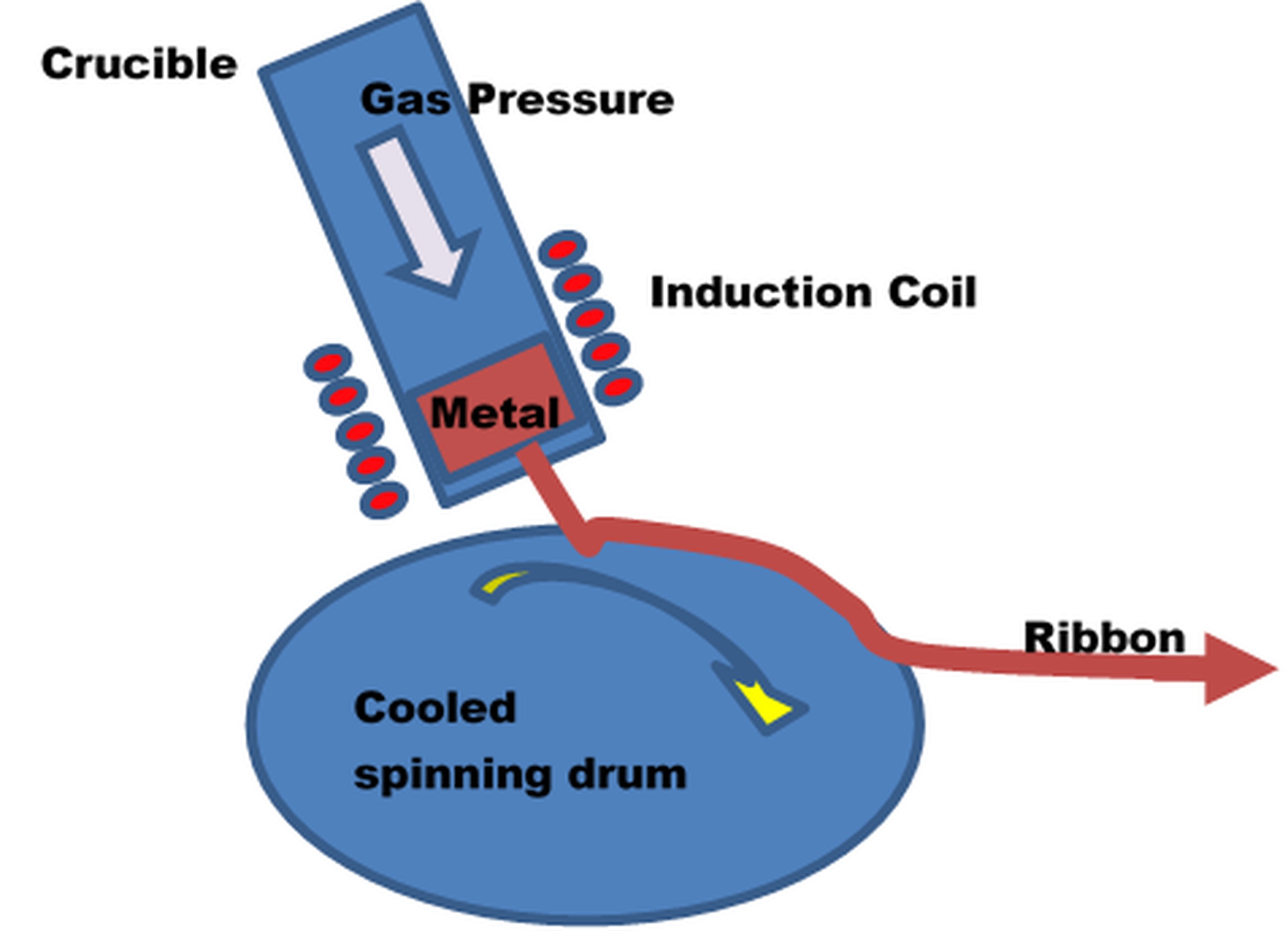
The third category involves a rapid quenching (i.e. an elevated cooling rate of 105 to 106K per second) of the molten particles when the molten droplets comes in contact with the substrate producing a fine-grained and homogeneous microstructure. The commonly studied rapid quenching technique is the chill block melt spinning process (see Figure 24), where the induction coil-heated molten specimen is extruded by the pressurized gas onto an internally water/ liquid nitrogen cooled rotating wheel or drum. When the extruded molted specimen comes in contact with the cooled drum, rapid solidification takes place. The continuous spinning of the drum separates the solidified ribbon while revealing new surface area to the flux of molten metal, thereby permitting continuous production.
. Comprehensive review on advanced RS techniques
An et al. [59] experimentally investigated the rapid solidification of continuously cast bearing steel GCr15 blooms under different casting conditions- electromagnetic stirring technique, mechanical soft reduction technique and permanent stirring in order to reduce macro-segregation and centre-carbon segregation. The casting speed, superheat temperature, specific water flow of second cooling zone and applied magnetic field are found to be significant process parameters. Electromagnetic stirring coupled with mechanical soft reduction at an elevated casting speed resulted in fewer centre-segregation ratio and in additionally lowered likelihood of network and banded carbide
Mullis et al. [60] proposed that the defects created in under-cooling due to thermal and solute diffusivity can be avoided by local mesh adaptivity, non-linear multi grid solver and implicit time stepping. Reduction of the operating point at intermediate under-cooling results in growth of non-dendritic morphologies like doublons and dendritic seaweed. Additionally, higher under-cooling re-generate stable dendritic growth. Herlach [61] observed that Gibbs free energy is generated by undercooling a liquid underneath its equilibrium-melting temperature thereby initiating the development of meta-stable solid. The electromagnetic and electrostatic levitation rapid solidification techniques exhibit an elevated under-cooling as liquid drop is levitated with no contact with the walls resulting in eradication of heterogeneous nucleation. This phenomenon creates metastable microstructures as supersaturated solid solutions and disordered superlattice structures of inter-metallics. Lavernia et al. [62] reviewed the intrinsic aspects and types of nucleation and the kinetics governing nucleation and subsequent growth of the crystal under various rapid solidification techniques for the metal and intermetallic composites.
Zhai et al. [63] simulated continuous rapid solidification of oil casing steel using a cellular automaton finite element to study the effect of casting speed, superheat temperature and specific water flow on the equiaxed crystal ratio and central shrinkage of round billets casted. The fabricated solidification structure at optimized process parameters was found to be with comparatively superior equi-axed crystal ratio and reduced mean grain radius. The duplex stainless steel predominantly exhibits a meta-stable duplex structure at ambient temperature paving way for additional exploitation of non- equilibrium phase transformation to fabricate duplex stainless steel of identical chemical and phase constituent albeit dissimilar microstructures. Accordingly, Wan et al. [64] used rapid solidification in combination with heat-treatment to attain 50/50 duplex structure. The result exhibited an equilibrium state for the phase constitution of duplex stainless steel after sufficiently long-time annealing, and established the non-equilibrium kinetics diagram of ferrite-to-austenite transition in cold-rolled duplex stainless steel. They also demonstrated that the duplex stainless steel with about 50% austenite phase manufactured through various non-equilibrium thermal process exhibited better yield strength and elongation.
Wang et al. [65] observed that the homogeneous microstructures and superior mechanical properties were obtained in the integrated rapid solidification and twin-roll casting of 7050 aluminum alloy at a higher roll casting speed and roll gap thickness. Drozdenko et al. [66] focused on fabrication of dilute Mg-Zn-Y alloy ribbons by melt spinning rapid solidification process with a different quantity of Zn and Y. The microstructural analysis indicates that melt spinning rapid solidification technique had resulted in inhomogeneous internal strain distribution in the bimodal microstructure, which is pivotal for superior mechanical performances. Jiang et al. [67] determined the influence of the expendable pattern shell casting process with vacuum and low-pressure input parameters on the filling ability of A356 alloy. The process parameters were ranked from higher to lower level of influence as: (1) gas flowrate, (2) casting temperature, (3) gas pressure and (4) vacuum level. The filling length was predicted to be positively and linearly proportional to all the input factors. A superior quality complicated thin walled specimen exhibiting rapid solidification can be manufactured with ease by this compound process.
Delshad Khatibi et al. [68] investigated the fabrication of D2 tool steel through impulse atomization in helium and nitrogen and water atomization. The results inferred that reduced eutectic portion can be achieved at increased cooling rates. Chang et al. [69] investigated the influence of input factors on rapid solidification of squeeze casting A356 alloy. Increased metal pressure and gate velocity resulted in a better filling of the mould thereby eliminating solidification shrinkage defect. He et al. [70] investigated the influences of various external physical fields (i.e. static and pulse magnetic field) on the micro-structure and mechanical properties of sub-rapid solidification-processed Al–Mg–Si alloy. Under the influence of the external field, fine and equiaxed α-Al structure are developed resulting in a steep reduction of the area fraction of non-equilibrium eutectic phases. Superior end casts were achieved in the presence of electromagnetic oscillation field.
Kanthavel et al. [71] investigated the influence of MS chills on rapid solidification of Steel using sand mould casting to eradicate shrinkage defects. Among the studied input factors (chill distance, chill thickness, pouring temperature and pouring time), the chill thickness was observed to have a huge impact on shrinkage defects. Zhang et al. [72] observed superior mechanical performances in ZM61 alloy subjected to rapid solidification. The reason for this betterment is the development of refined dendrite microstructure and the strengthening MgZn2 phase distributed inside the matrix. Additionally, ZM61 alloy subjected to rapid solidification exhibited superior corrosion resistance in comparison to the ZK60 alloy formed by extrusion and pure Mg alloys. The study thus illustrated the frontier of rapid- solidification process in fabrication of Mg alloys under structural and corrosive applications.
Öztürk et al. [73] investigated the tribological characteristics of the textured melt spinning wheel instead of smooth wheel for powder manufacturing application by atomizing the molten metal. The results showed that the smooth wheel is more suited for ribbon fabrication and textured wheel for powder production. The wheel speed and melt temperature exhibited a negative effect on ribbon thickness and powder size while gas ejection pressure showed a positive impact. The fabricated powders and ribbon of reduced size and thickness respectively showed an equiaxed microstructures with reduced mean grain size. Sahoo et al. [74] demonstrated through numerical simulation and experimental investigation that high speed twin-roll casting exhibiting rapid solidification is a candid manufacturing process for layered specimen. Kenel and Leinenbach [75] demonstrated that the cooling rate in rapid solidification predominantly determines the microstructure of binary TiAl alloys.
Mattson et al. [76] demonstrated the efficiency of Planar flow casting, which is a rapid solidification technique for the fabrication of ultra-energy-efficient amorphous and nanocrystalline thin metallic glass (TMG) alloys. Because of the elevated brittleness of TMG and crystalline alloys, they can be fabricated by planar flow casting even though they have unique solid-state atomic structures. The study also developed a scaling law to predict fabricated ribbon dimension which is heavily influenced by specimen’s thermal characteristics and heat transfer ratio of the planar flow casting equipment.
Mapping Of Future Research Directions Using Co-Occurrence Network Analysis
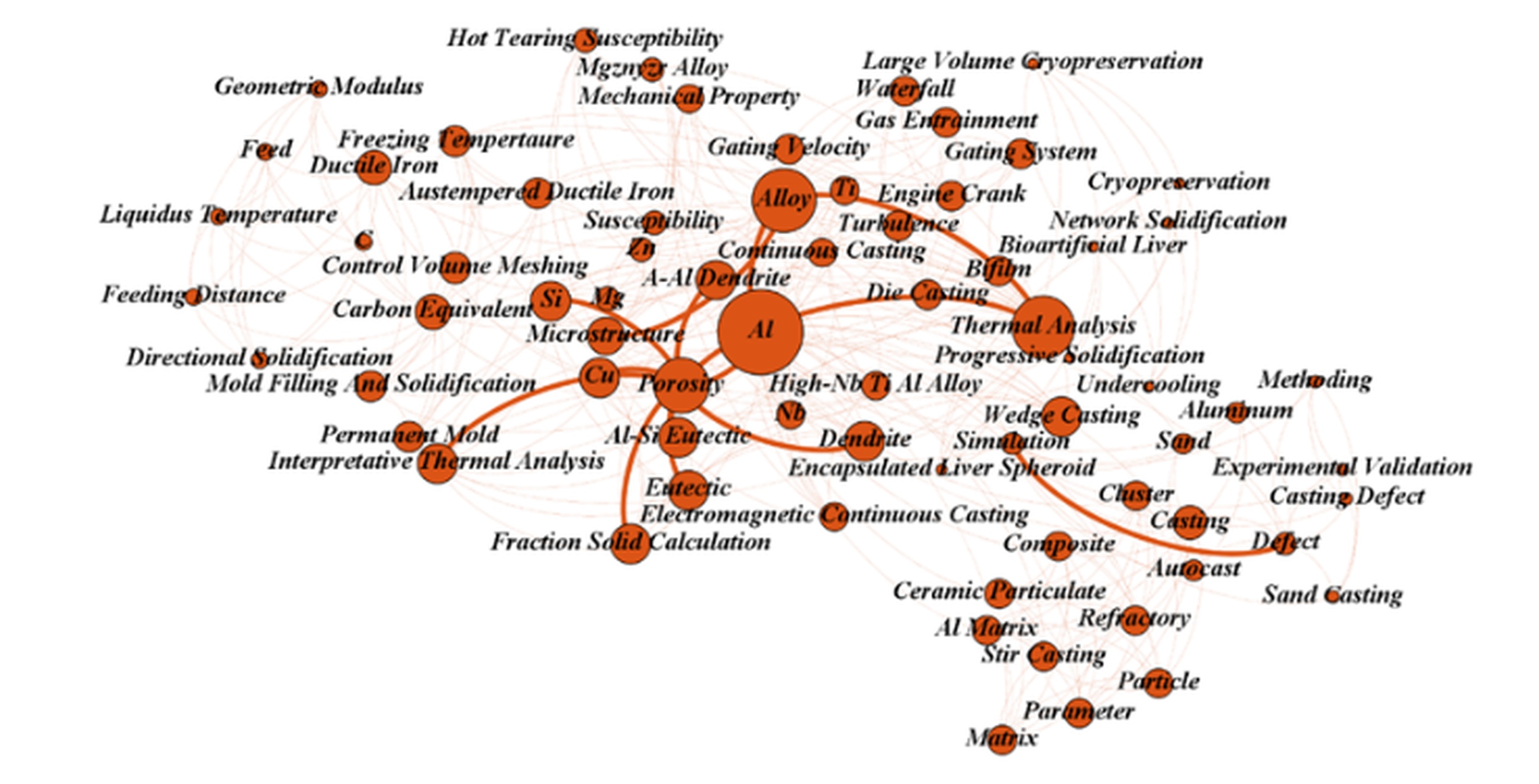
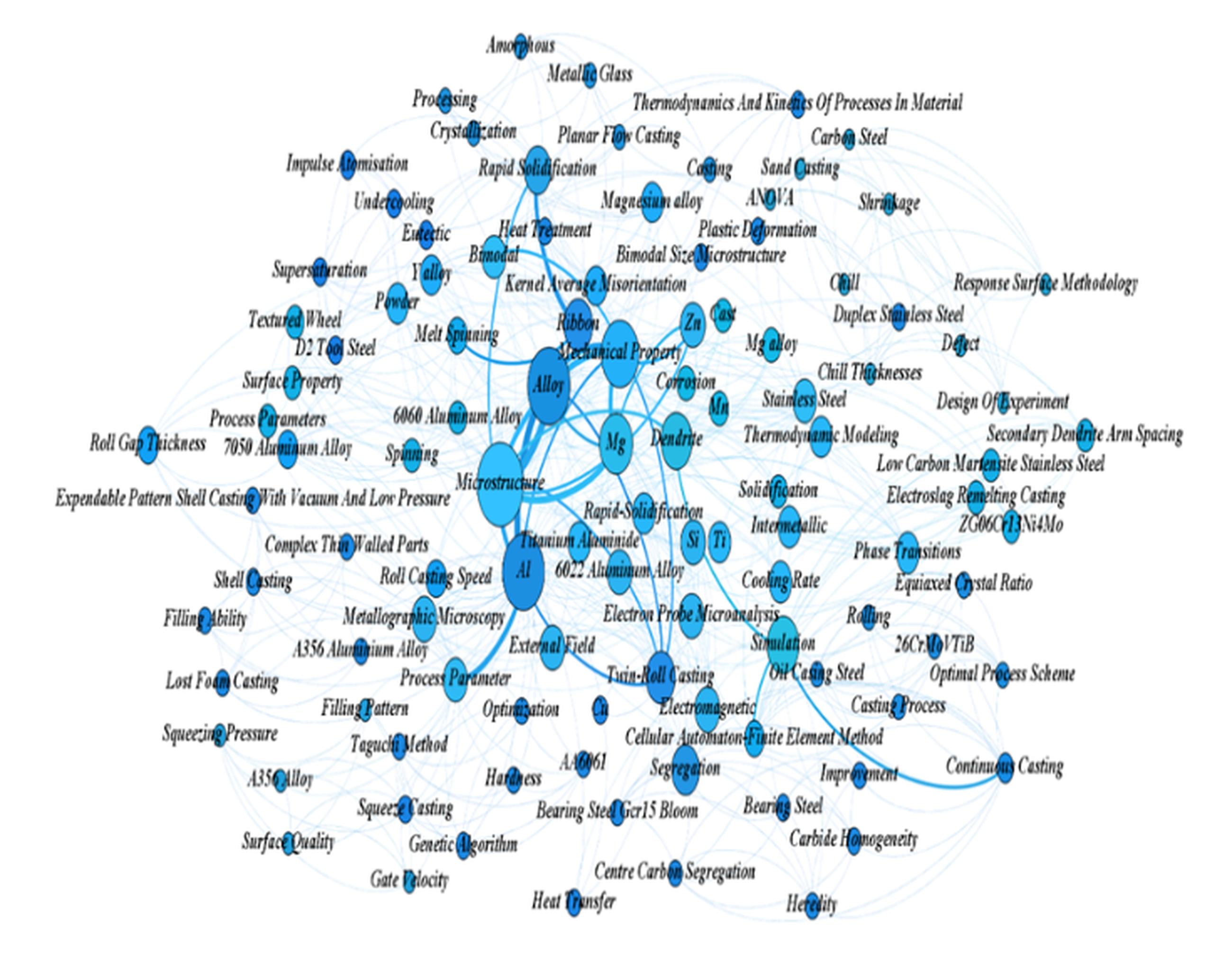
In order to determine the most studied and future research scopes in the four domains of the solidification namely directional, progressive and rapid solidification and inoculation treatments, a keyword co-occurrence network (KCON) is constructed following Rajagopal et al. [9]. In each domain, based on the above reviewed research papers, a KCON is constructed where each node in the network represents the author-defined keyword and a link/edge is established between two nodes if a research paper carries both the keywords. More the number of research papers carrying the two keywords, more will the edge weightage between the said keywords. The author-defined keywords are extracted using Bib Excel software and using the extracted data, the KCON is visualized in Gephi software. Figures 25 (a-d) show the KCON of directional, progressive, rapid solidification and inoculation treatments domain, respectively and node sizes are proportional to their Eigenvector score [9], which determines how central (important) a node is in a network. The nodes concentrated towards the center of the network represent the most-studied areas and nodes dispersed away from the center denote the least researched area. This distribution of nodes in KCON is achieved by employing Force Layout algorithm in Gephi.
From Figure 25(a), it can be observed that the DS is predominantly studied in turbine blade fabrication and single crystal growth. The dispersed nodes in the KCON (see Figure 25(a)) indicate the following future research directions.

From Figure 25 (b), it can be inferred that progressive solidification is predominantly studied in Continuous, sand, wedge and Die- casting and primarily in fabrication of Aluminum alloys. The design of gating system to eliminate gas entrapment and thermal analysis of solidification behavior are other prominently researched areas. The least addressed directions include:
The application of progressive solidification in cryopreservation.
Progressive solidification of Metal matrix ceramic composites fabricated by stir casting.
Inoculation treatment in progressive solidification to eradicate hot tearing susceptibility.
Figure 25 (c) shows that rapid solidification under twin-roll casting of Al and Mg alloys are most studied in the presence of external field effect. The future research directions are inferred as following:
Formation of bimodal microstructure under rapid solidification coupled with heat treatment.
Fabrication of metallic glass structures using rapid solidification through planar flow casting.
Eradication of center-carbon segregation and achieving carbon homogeneity.
From Figure 25(d), it can be inferred that self-inoculation method under rheo-die casting is most studied especially in ductile cast iron and Al alloys. The dendrite arm spacing and segregation under inoculation treatment with Ti, B, Co and Si as primary/ secondary inoculant are much researched.
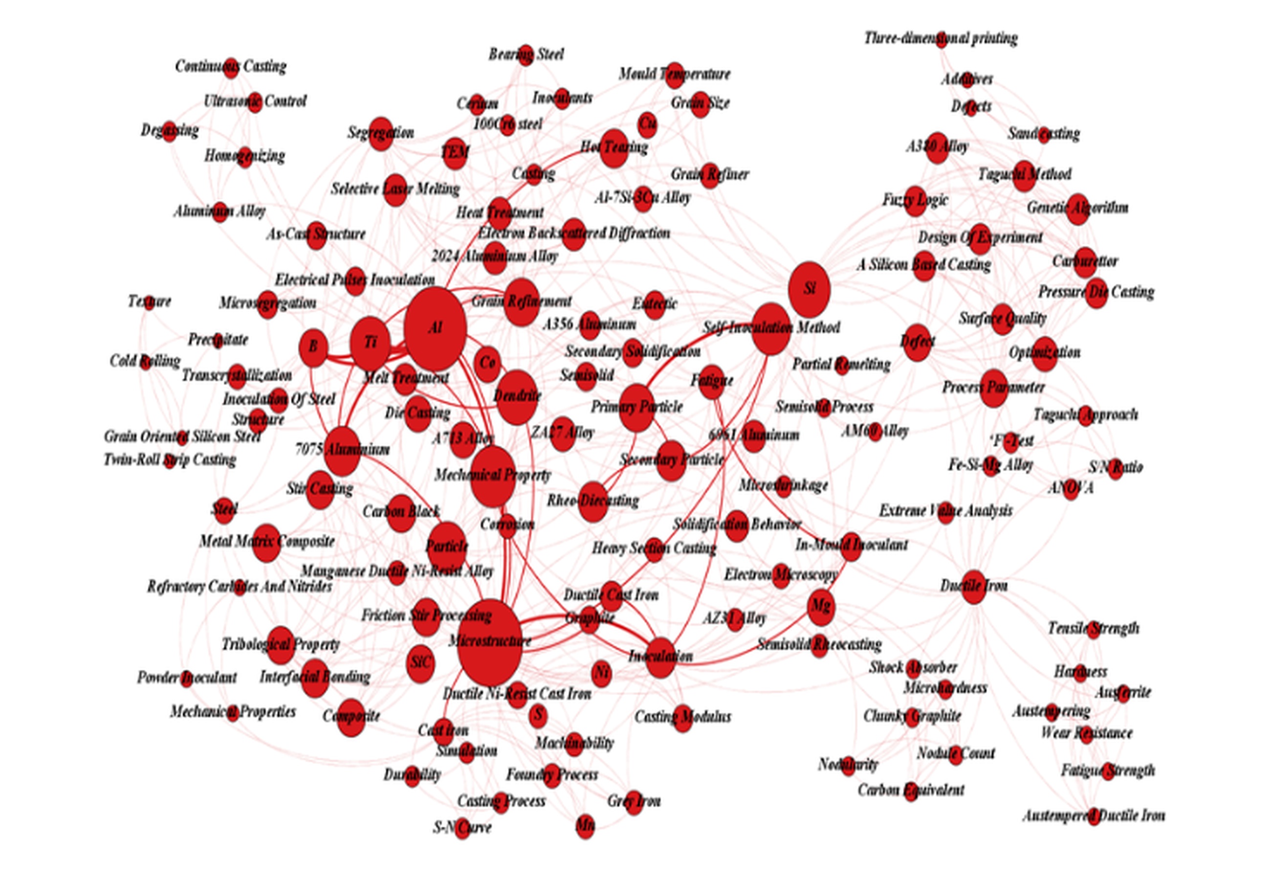
The future research gaps under inoculation domain are inferred as
Effect of refractory carbides, Cerium and nitrides as inoculates in fabrication of metal matrix composites;
Effect of inoculation treatment in additive manufacturing;
Eradication of micro-segregation by electric pulse inoculation.
. CONCLUSIONS
This work has systematically reviewed 65 papers detailing the principles of solidification in casting and the various solidification techniques (directional, progressive, rapid solidification and inoculation treatment) studied in improving the crystal structure. A network analysis is presented in the four research domains of solidification and the future research directions in each domain are mapped. Major findings are reported as
1) Compared to the conventional DS techniques, advanced DS techniques such as the centrifugal casting with DS through a copper plate chiller, counter gravity casting with DS under pressure and advanced counter gravity casting with induction skull melting resulted in effectively controlled lotus (porous) cast metal, enhanced filling quality of melt with flat isotherms, and macro-defect free casts respectively. DS is predominantly studied in turbine blade fabrication and single crystal growth. Fabrication of porous dental/bio-medical implants using DS, the effect of inoculation treatment in DS cast and study of DS of ternary alloys in multi-shell mould casting need attention.
2) Modified inoculation techniques such as rheo-casting process coupled with SIM, complex inoculation and austempering with inoculation resulted in near spherical primary phase dendritic microstructure, reduced trans-crystallization, and spherical carbon structure respectively. SIM under rheo-die casting is most studied especially in ductile cast iron and Al alloys. The dendrite arm spacing and segregation under inoculation treatment with Ti, B, Co and Si as primary/ secondary inoculant are much researched. The effect of refractory carbides, Cerium and nitrides as inoculates in fabrication of metal matrix composites, the effect of inoculation treatment in additive manufacturing and eradication of micro-segregation by electric pulse inoculation are the future research streams in inoculation domain.
3) Electromagnetic stirring coupled progressive solidification broke the initial dendrites and enhanced the heterogeneous nucleation, thereby eliminating shrinkage and porosity. Progressive solidification is predominantly studied in Continuous, sand, wedge and Die- casting and primarily in fabrication of Aluminum alloys. The design of gating system to eliminate gas entrapment and thermal analysis of solidification behavior are other prominently researched areas. The applications of progressive solidification in cryopreservation, in Metal matrix ceramic composites fabricated by stir casting and in inoculation treatment to eradicate hot tearing susceptibility need attention.
4) Advanced RS techniques such as electromagnetic stirring coupled with mechanical soft reduction, electromagnetic/ electrostatic levitation RS and Planar flow casting resulted in fewer center-segregation ratio, eradication of heterogeneous nucleation, and ultra-energy-efficient amorphous and nano-crystalline TMG alloys respectively. RS under twin-roll casting of Al and Mg alloys are most studied in the presence of external field effect. The future research directions in RS domain are inferred as formation of bimodal microstructure under RS coupled with heat treatment, fabrication of metallic glass structures using RS through planar flow casting and eradication of center-carbon segregation and achieving carbon homogeneity.