
Introduction
Induction Motors (IMs) are widely used in industrial applications due to their robustness, low maintenance requirements and cost-effectiveness. However, controlling high precision speed remains a challenging task especially under varying load conditions and parameter uncertainties [1-2]. To overcome these challenges, Indirect Field-Oriented Control (IFOC) has been widely adopted as it allows decoupled control of flux and torque making the behave motor induction similar to a separate DC motor excited [3-4].
The core control speed loop in an IFOC scheme lies the Proportional-Integral controller that is traditionally favoured for its simplicity and effectiveness to maintain a desired speed [5]. However, the conventional PI controller often suffers from limitations such as poor performance in transient conditions, sensitivity to tuning parameters and integrator windup during large disturbances or saturation [6-8].
To debate these issues, several modified PI controllers have been proposed including the Hyperbolic PI [9], Variable Gain PI [10], and Anti-Windup PI regulators [11-12]. Each strategy introduces specific enhancements to improve dynamic response, robustness, and overall system performance. The HPI utilizes nonlinear hyperbolic functions to enhance gain response, VGPI adapts controller gains in real-time based on system error or dynamics, while the Anti-Windup PI evaluates integrator saturation problems.
In the last few years, several technics for controlling the speed regulation of induction motors have been developed. In reference [13], Soukaina El Daoudi et al. presents an improved direct torque control strategy for induction motors, utilizing a five-level diode-clamped inverter and a sensor-less algorithm. The study reduces torque and flux ripples, and the authors validate their method's efficiency by comparing it with other inverter topologies. Authors in [14] present two modified strategies for Direct Torque Control (DTC) of asynchronous motors, focusing on improving performance and reducing ripples. It introduces a sliding mode control approach combined with sinusoidal pulse width modulation, aiming to enhance dynamics and reliability without the use of mechanical sensors. Najib El Ouanjli et al. [15] present an improved Direct Torque Control (DTC) strategy for induction motors, utilising a twelve-sector approach combined with a back-stepping speed controller and a robust model reference adaptive system for stator resistance estimation. The proposed methods enhance motor performance and stability, validated through simulations and experiments using a dSPACE DS1104 board.
Emre Celik et al. [16] used a non-linear PI controller in order to improve velocity regulation in PMDC motor drive. The obtained numerical results are in good accordance with other results in the literatures, the proposed non-linear PI (EXP-PI) controller achieved a good performance. Nichat Orturk and Emre Celik [17] proposed a new alternative method based on SOS algorithm (Symbiotic Organisms Search) to improve a Direct Current (DC) motor drive's dynamics and performance; the obtained numerical results demonstrate that the proposed algorithm gives an important optimization for effective PI controller design. A cascade one proportional derivative incorporating filter (c-1PD f -PI) controller designed for effective speed control of brushless DC (BLDC) motors is introduced in [18], it demonstrates superior performance compared to traditional controllers through numerical simulations and experiment results.
The objective of this work attempts to present a comparative analysis of different PI-based control techniques for speed regulation of a squirrel-cage induction motor. The performance of each controller is examined under varied load conditions and reference speed profiles based on comprehensive simulations using MATLAB/Simulink. The goal is to discover the most effective control strategy for ensuring robustness, adaptability and fast response.
The main contributions of this research are summarized as follows:
The proposition of four modified speed regulators based on conventional PI.
The development of these enhanced speed regulators.
Improve the robustness of these speed regulators.
Development of a controller more performant than the conventional PI regulators with a minimum cost.
The remainder of the manuscript is organized as follows: in Section 2, the mathematical model of the studied induction motor is presented. The control strategy of the five proposed controllers is described in Section 3. Primary part of Section 4 shows the numerical simulation results of the controllers PI, IP, HPI, PI Anti-windup and VGPI. A performance evaluation of each controller is also evoked. The second part of Section 4 is focused on the quantitative performance comparison of the controllers. Finally, a conclusion is presented in Section 5.
Mathematical Modeling Of The Induction Motor
The dynamic behaviour of the induction motor is modelled using the standard d-q axis equations in the synchronous reference frame [19]. The mathematical model includes stator and rotor voltage equations, flux linkages and electromagnetic torque expressions. The model assumes balanced three-phase inputs, neglects magnetic saturation and core losses for simplicity. The extended nonlinear state-space model (with the load torque introduced as a state variable) of the induction machine in the generalized rotating d-q reference frame is:
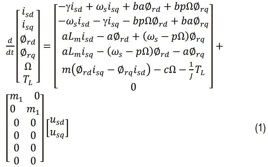
where: isd,isq - respectively, the direct and quadrature components of the stator current (A), usd, usq - respectively, the direct and quadrature components of the stator voltage (V), ϕrd, ϕrq - respectively, the direct and quadrature components of the rotor, ϕr - rotor flux (Wb), TL - the load torque (Nm), ωr, ωs, ωg - respectively, the electrical angular velocities of the rotor, stator and slip (rad/s), Ω - the mechanical angular velocity of the motor (rad/s).
( )* - indicates the reference quantities of the control inputs.
The parameters a, b, c, gamma, sigma, m, m1 and are defined as follows:
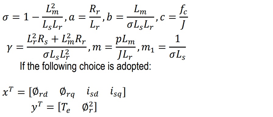
then the state-space representation becomes:
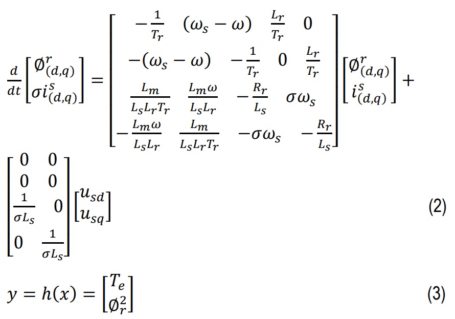
The vectors: dphi_r/dt, and sigma di_s/dt - represent respectively, the slow and fast modes of the model. 0<sigma<1.
where: Rs, Rr - respectively, the rotor and stator resistances (Ω), Ls, Lr, Lm - respectively, the cyclic inductances of the stator, rotor and mutual inductance (H), p, J, fc - respectively, the number of pole pairs, moment of inertia and viscosity coefficient, Tr, σ - respectively, the rotor time constant and Blondel dispersion coefficient, Te - electromagnetic torque (Nm).
Control Strategy
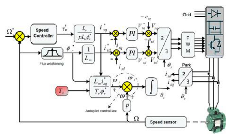
The control system is based on indirect field-oriented control [20], which aligns the rotor flux along the d-axis and decouples the torque and flux control (Fig. 1).
The outer speed control loop uses the PI, HPI, VGPI, or Anti-Windup PI controller to generate the reference current for the inner current loops.
Speed control
To improve the dynamic performance of speed regulation in an Indirect Field-Oriented Control (IFOC) scheme, alternative controllers such as the Integral-Proportional (IP) [21], Hysterisis PI [16], PI Anti-windup [23-24], and Variable Gain PI (VGPI) [25] controllers are implemented instead of the conventional Proportional-Integral controller.
PI controller (Proportional-integral controller)
To improve the dynamic performance of speed regulation in an Indirect Field-Oriented Control (IFOC) scheme, alternative controllers such as the Integral-Proportional (IP) [21], Hysteresis PI [16], PI Anti-windup [23-24], and Variable Gain PI (VGPI) [25] controllers are implemented instead of the conventional Proportional-Integral controller.
The PI controller is a classical control strategy that combines proportional and integral actions to minimize the error between a system's desired and actual outputs.

where:
u(t) - controller output (reference torque or speed)
e(t) - error signal
k_p, k_i - respectively, proportional gain and integral gain.
To design the PI controller, the dynamic induction motor model is considered under the regulated rotor flux assumption. Given that the current control loop (electrical dynamics) responds much faster than the speed control loop (mechanical dynamics). The stator current components isd, isq are assumed to follow their reference values instantaneously. This time-scale separation allows for a simplified controller design focused on mechanical dynamics. The speed controller block diagram is presented in (Fig. 2):
where:
kp, ki - PI controller gains
Tvd - computation time delay
Gfi - current loop transfer function
Kt=(3)/(2)p(Lm)/(Lr)ϕr* - motor torque constant
Ω - mechanical angular velocity (rad/s)
( )* - indicates the reference quantities or control inputs.
In order to simplify the computation of the parameters related to this type of controller, the block diagram shown in (Fig. 2) is assumed to be reducible to a classical PI controller. To this end, the delay Tvd as well as the current loop dynamics are neglected with respect to the speed dynamics.
The resulting expression is then given by:
The transfer function derived from Eq. (5) can be expressed as a second-order system of the form:
where, ξ - denotes the damping ratio, ωn - represents the undamped natural frequency.
The following identities can be established:
It is worth recalling the expressions for the system overshoot.
IP controller (Integral-proportional controller)
The block diagram of an IP controller is shown in Fig.3. This type of controller applies a proportional action to the measured output and an integral action to the error, ensuring the elimination of the steady-state error.
where: k=(1)/(fc), τ=(J)/(fc) - the mechanical time constant, fc - viscous friction coefficient.
Accordingly, the following identities can be established:
HPI controller (Hysteresis PI controller)
The HPI controller is an advanced form of the PI controller that includes a dynamic adaptation of the gains for better performance in terms of robustness and system stability [26].

where: f(θ) - a dynamic gain adaptation function dependent on the hysteresis threshold h, h - defines the hysteresis band on the speed error (-e(t)≤h≤+e(t)).
PI anti-windup (High-performance PI controller)
The actuator is saturated when the anti-windup PI controller is designed to prevent integrator windup by correcting the integral term [27]. The control law is modified by adding feedback correction proportional to the difference between the saturated and unsaturated control signals. (Fig. 4).
The control law is given as below:
kw - is the anti-windup gain, usat(t) - is the saturated control signal, u(t) - is the pre-saturation signal.
When saturation occurs, the feedback mechanism modifies the integral action to bring the error toward zero while keeping the controller output at the saturation boundary.
VGPI controller (Variable-gain PI controller)
The VGPI controller adjusts the controller gains based on the system's state or operating conditions to improve performance in varying environments [28]. This is typically used in time-varying parameter systems.
where: et - is the error signal, and kp, ki - are respectively, time-varying proportional gain and time-varying integral gain
kpi , kpf - Are respectively the initial and final values of the proportional gain, kif - is the final value of the integral gain, while the initial value of the integral gain is considered zero to help eliminate overshoot, ts - is the saturation time, n - the degree of the transient response function, defined as the degree of the variable gain controller.
Computational burden analysis
From a computational point of view, the classical PI and IP controllers present the lowest complexity due to their simple linear structure and minimal arithmetic operations, Eqs. (6-9).
The anti-windup PI controller introduces a slight additional computational burden due to the integrator saturation mechanism, which requires a few extra operations per cycle to handle windup correction. In contrast, the HPI and VGPI controllers require higher computational effort due to nonlinear gain adaptation and time-varying parameters.
In contrast, the HPI controller demands higher computational effort because of its nonlinear hysteresis logic and gain adaptation rules. The VGPI controller requires the most significant overhead, as it involves real-time calculation of time-varying gains based on the scheduling law given in Eq. (13).
Given the relatively low number of operations involved, all controllers are considered algorithmically feasible for real-time implementation within typical motorcontrol sampling periods on common digital platforms such as DSPs or microcontrollers
Controller parameter values
Using the motor parameters from Tab. 2, the base proportional and integral gains kp & ki are calculated from Eq. (7).
The values of the controller gains used in the simulation were calculated mathematically and subsequently fine-tuned using the trial-and-error method.
All speed controller parameters used in the simulations are summarized in Tab. 1.
Tab. 1
Controller parameters
Simulation Results
The numerical simulations are carried out in MATLAB/Simulink using the same motor parameters and load conditions. The test scenarios include speed tracking performance for step and ramp reference changes, load disturbance rejection, and sensitivity to parameter motor variations.
The results are compared in terms of rising time and settling time, overshoot and steady-state error and robustness.
The induction motor parameters are shown in Tab 2.
Tab. 2
Table of the induction motor parameters
Rs | 4.850Ω | Pn | 1,5kW | fc | 0.00114(Nms/rad) |
Rr | 3.805Ω | In | 6.5A | p | 2 |
Ls | 0.274H | Vn | 220V | fn | 50Hz |
Lr | 0.274H | ωn | 149rad/s | ||
Lm | 0.258H | Jn | 0.031kg/m2 |
Classical profile
In this test scenario, the reference speed is defined as a smooth step reaching 100 rad/s. The reference flux is maintained at 1Wb throughout the simulation.
A constant load torque of TL=10Nm, is applied between t=1s and t=2s.
This profile serves as a benchmark case evaluation for the nominal behavior and baseline performance of the proposed control strategies under standard operating conditions.
According to the simulation results shown in (Fig. 5), the following observations can be done:
The PI and VGPI controllers exhibit the highest overshoots and demonstrate weaker disturbance rejection capabilities. The simulation results of the stator three-phase currents show that no overshoot is observed, confirming the effectiveness of current limitation.
Under load disturbance, the HPI (Hysteresis PI) controller appears to deliver superior performance. With an appropriate chosen parameter value, it effectively dampens speed oscillations.
The value h=0.01 is chosen for simulation to demonstrate precise speed regulation under ideal conditions. In practice, h can be adjusted based on sensor resolution and noise tolerance.
The speed response illustrated in (Fig. 5), demonstrates that following the application of a load torque of 10 Nm at t = 0.5s, the actual speed tracks the reference speed. However, notable transient phenomena are observed, characterized by pronounced overshoot and disturbance rejection effects.
The PI Anti-windup and IP controllers show improved performance in the presence of load disturbances.
Speed reversal profile
A reversal in the direction of rotation is imposed between t=1s and t=2s. The reference flux, ϕ*=1Wb. A constant load torque of 10 Nm is applied starting at t=0.5s (Fig. 6).
The conventional PI controller exhibits the weakest disturbance rejection capability and the highest overshoot among all the tested strategies. Similarly, the VGPI controller demonstrates limited effectiveness in disturbance rejection. Although the HPI controller fails to maintain accurate speed tracking during deceleration phases. It achieves superior performance in rejecting external disturbances.
In contrast, both of the IP controller and the anti-windup PI controller deliver the best overall performance, excelling in both speed tracking and disturbance rejection.
Impact of parametric variations on IFOC performance
This scenario evaluates the robustness of the controllers under parametric uncertainties. The rotor resistance Rr varies by 50% and +100% of its nominal value Rrn=3.805Ω, while the moment of inertia J is altered by -50%, 100% and 400%.
The reference speed is maintained at 100 rad/s, with a constant load torque of 10 Nm applied between t=1s and t=2s.
According to the numerical simulation results for the critical profiles, (Figs.7 - 11).


The following observations can be made: while each controller exhibited satisfactory performance in both speed tracking and disturbance rejection, none succeeded in achieving robust decoupling against variations in the most influential parameter within an IFOC strategy, specifically the rotor resistance
The IP, VGPI, and PI Anti-windup controllers exhibit satisfactory performance under various conditions, including load disturbances (Fig.5), speed-tracking (Fig.6), and even in the presence of machine parameter variations (Figs. 7- 11).
The metrics performance summary for the various speed controllers, highlighting key aspects such as disturbance rejection, speed tracking accuracy, and overshoot behavior are presented in Tab. 4.
The quantitative performance indices (Tab. 3) confirm the qualitative (Tab. 4) observations. The VGPI controller exhibits the lowest MSE, IAE, and ISE values, indicating superior reference tracking accuracy and disturbance rejection. The PI anti-windup and HPI controllers also show improved performance compared to the classical PI and IP controllers, particularly under load disturbances and parametric variations.
Conclusion
This study represents a comprehensive comparative analysis of several PI-based controllers namely the classical PI, Integral-Proportional (IP), Hyperbolic PI (HPI), PI with anti-windup compensation, and Variable Gain PI (VGPI) for the speed regulation of an induction motor under field-oriented control. The objective is to assess their dynamic robustness and performance in the presence of nonlinearities and parametric uncertainties.
The classical PI controller, despite its widespread use and simplicity, shows limitations in terms of overshoot, settling time and robustness against parameter variations. The IP controller demonstrated improved damping characteristics and reduced overshoot but remained moderately sensitive to system uncertainties. The HPI controller, by introducing nonlinear characteristics through hyperbolic functions, achieved a superior balance between fast response and robustness, particularly under transient conditions.
The anti-windup PI controller significantly mitigated the adverse actuator saturation effects, leading to improved dynamic performance. Finally, the VGPI controller, which adapts its gains in real-time based on system behaviour, consistently outperformed the others across all metrics evaluation, particularly in robustness, tracking precision and disturbance rejection. The results of our work will serve as a reference for comparison with other types of controllers (scheduling controller, sliding controller, fuzzy controller, etc.).