
Introduction
Implementation of unmanned vehicles. The operation of offshore structures and installations at sea requires the application of novel systems for monitoring of such the critical infrastructure. The need to implement the new technological solutions originates from the challenges following from both the normal and abnormal operational conditions. There are the hazards that originate from terrorism and military conflicts. A fast development of new technologies enables the implementation of deck robots and unmanned maritime vehicles as the USV/AUV platforms (USV – Unmanned Surface Vehicles, AUV – Autonomous Underwater Vehicles) for the permanent monitoring of maritime critical infrastructure (MCI). The operational and safety systems supported by the deck robots and USV/AUV platforms may provide an increase in the level of functionality, performance, and safety of MCI infrastructure. Combining the USV/AUV platforms with the novel systems of sensors and effectors and then linking them with the existing operational matitime systems may help to create a novell generation of monitoring and control maritime systems. Development of the USV/AUV platforms ready for the monitoring activities at sea is a difficult task. The development of such the platforms equipped with the modern sensors and effectors requires a collaboration of several partners. Before the further knowledge is introduced, it should be underlined that a precise prediction of the performance characteristics of such the platforms is a key factor in estimation of a platform dynamics including the resistance, demanded power of propulsion system, capacity of source of energy, and seakeeping of each platform under consideration. A proper prediction of the platform dynamics including the operational characteristics is the basis for design of the sensors, effectors, and control systems. These are the main components which the working conditions decide about the range and autonomy of each platform. A precise estimation of the capacity of the source of energy necessary for the propulsion purposes and work of its sensors and effectors may enable each USV/AUV platform to be operated during 2, 4, 8, 12, and 24-hours missions at sea. The above approach enables to evaluate a potential of each platform to be implemented for the monitoring activities. This approach may substantially increase the level of safety of the MCI infrastructure.
Unmanned maritime vehicles. The last decade was a period of rapid development and implementation of unmanned maritime vehicles. There is a growing interest in implementation of fully developed and combined unmanned autonomous AI-driven maritime platforms. The main drivers towards the development of such the platforms are the technologies combining the concepts of autonomous systems (platforms), hull form geometries, innovative construction materials including nanomaterials and intelligent materials, innovative energy supply sources, propulsion systems combining efficient and silent engines and propellers, sensors, effectors, and innovative IT technologies including the systems of navigation, communication, and control. Within these technologies is a role to play by the artificial intelligence (AI) technology used by the advanced control systems. An additional set of features that the USV/AUV platforms may possess are the stealth-based and bio-technology-based solutions.
A successful final solution concerning the USV/AUV platforms can be obtained using a procedure consisting of the following research steps: definition of the USV/AUV platform, definition of the mission, definition of the requirements relating to the platform and mission, identification of options of the platform solutions, examination of tradeoffs, development of the platform (technologies, approaches, methods, materials, structure, propulsion, source of energy, statics, dynamics, specifications (such as parameters and characteristics, etc.), cost analysis for the project work plan, time schedule, expenditure, selection of the platform solution and design. It follows from the experience that it is necessary to define the key design and operational drivers depending on the requirements, which are very important when designing a USV/AUV platform that satisfies the standards and criteria of functionality, performance, and safety [1] [6] [7] [18].
In general, unmanned maritime platforms may be of different types: unmanned surface vehicles (USV), unmanned underwater vehicles (UUV), autonomous underwater vehicles (AUV), and remote (underwater) operated vehicles (ROV). The USV and AUV platforms may be treated as semi-autonomous if there is no direct energy supply and control connection with the operator. If such platforms are pre-programmed, from the mission point of view, they may reach the first, second, or even third level of autonomy. In the future, the pre-programmed USV/AUV platform vehicles, which may perform the locomotion and have a full set of sensors and effectors onboard, including the manipulators, could be treated as fully autonomous platforms if they may have a high precision positioning system onboard to ensure self-stabilization of the position and the correct self-orientation of the platform. These should be combined with the mission objectives, including all the particular tasks to be performed. The domains of the application of the USV and AUV platforms depend mainly on the objectives of the missions in operation. They may be a typical patrol, monitoring, reconnaissance, or even combat. The USV and AUV platforms may be double-mode platforms and depending on the mission, they should be equipped with either sophisticated reconnaissance electromagnetic, hydro-acoustic, or other IT‐based subsystems [1] [2] [10] [11] [12] [13] [14] [15] [16].
. OBJECTIVES OF USV/WIG PROJECT
The aim of the project is to develop a technology demonstrator of the unmanned USV-WIG type platform (USV - Unmanned Surface Vehicle, WIG - Wing in Ground Vehicle) using the surface effect supporting the operations of naval military units with the technological readiness level of TRL VI.
The specific objectives of the proposed research include:
- development of a demonstrator of a new equipment model that would increase the defense potential and security of the state,
activation of Polish research centers and academic staff for research and continuation of work aimed at the practical use of the project results in order to conduct development studies aimed at creating a vehicle prototype (PGT IX).
The basic tasks assigned to the platform include:
- performance of tasks over water areas and over land near the coastline,
- carrying cargo and/or on-board equipment of a given mass,
- possibility of taking off from water and splashing down,
- ability to fly at a minimum altitude using the surface effect.
A scheme explaining the relation between the platform hull form geometry and minimum altitude distance from the free water surface close to reality is presented I Figure 1 [23].
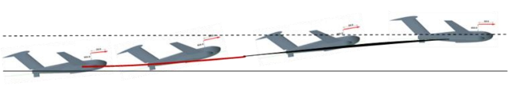
Fig. 1. A scheme presenting the relative values between the platform hull form geometry and minimum altitude distance from the free water surface close to reality [23]
There is a link between the research objectives and the objectives of other research programmes and projects which were analyzed by the Consortium of the Gdańsk University of Technology, the Military University of Technology and the Air Force Institute of Technology as part of the preparations for the project [23].
. A CONCEPT OF THE USV/WIG UNMANNED PLATFORM USING THE SURFACE EFFECT
There are a few major objective concerning the USV-WIG platform under consideration:
- platform should be unmanned,
- platform should work using the surface effect (wing in ground effect),
- platform should be able to support the military logistic operations in maritime areas,
- development of the platform demonstrator should enable to obtain a new model of equipment designed to increase the defense potential and security of the state (prototype).
The platform demonstrator major features are as follows:
- platform is a kind of a system of systems,
- platform is equipped with the propeller combustion drive system,
- platform has installed a remote control system (navigation, communication) at the demonstrator testing stage,
ultimately the platform should operate in programmable, semi-autonomous or autonomous mode.
The platform functionalities are as follows: mass, payload, speed and operating range. The final tests of the platform demonstrator should be performed in conditions close to the real simulated operating conditions.
As it was mentioned before, the aim of the presented research is to develop the concept of an unmanned high speed USV-WIG platform using the surface effect, which could be able to support the logistics operations of troops in sea areas. The outcome of the research, the design and operational criteria will be verified during tests of the platform demonstrator in conditions close to real ones. The subject of the research is a platform with the hull length and wingspan of over 3 meters. It means that the dimensions are much bigger than in the case of medium sized drones.
The platform hull is divided into integrated parts:
aerodynamic and
- hydrodynamic.
The aerodynamic part of the platform consists of the following components:
- wings (lifting airfoils) integrated with the upper part of the main hull,
- side airfoils (winglets) mounted on the side hulls of the platform,
- upper parts of the side hulls,
- foils (rudders): vertical and horizontal.
The hydrodynamic part of the platform includes the components as follows:
- lower (underwater) part of the main hull together with the transverse step (transom),
- lower underwater parts of the side hulls,
- additional elements, including the rudders and peculiarities of the hydrodynamic hull.
The platform hull structure is devided into modules. Remembering that the wingspan is over 3 meters the modularity of the platform is presented in Figure 2 [23].
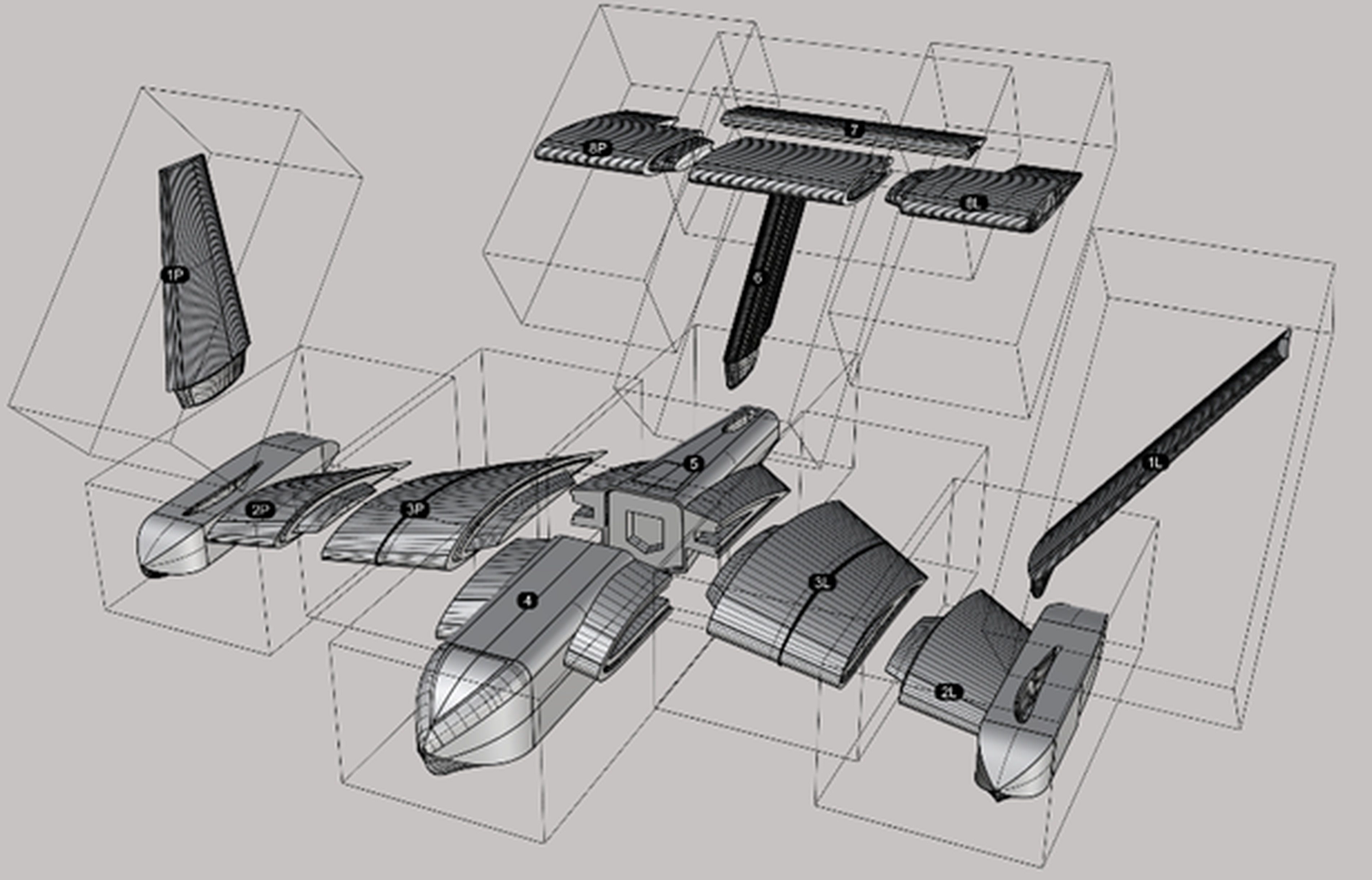
Fig. 2. A general modular structure applied for the USV-WIG platform but different from that in reality [23]
The modular structure of the USV-WIG platform is necessary from the deployment point of view as the airborne, water surface and land platforms are planned to be used for the USV-WIG platform deployment [23].
. THE RESEARCH METHOD
The research method when analyzing the aero-hydrodynamic characteristics of the USV-WIG platform using the surface are closely related to parallel solution of the following research and design problems:
- analysis of technological and operational conditions for conducting operations using the platform,
- development of the platform's aero-hydrodynamic design,
- development of dynamic models and laboratory tests using the Hardware in the Loop method,
- development of the platform’s structural design and strength estimation,
- development and integration of navigation and control systems in laboratory conditions,
- development and integration of a radio communication system with ground and avionic systems of the platform.
The key problems of the analysis of the USV-WIG aero-hydrodynamic characteristics belong to development of the platform's aero-hydrodynamic design.
From the research point of view there is a question if the research concerns either the remote controlled or autonomous platform.
For the remote controlled platforms the most important key design drivers are:
- basic design assumptions (requirements): mass, payload, speed, flight altitude (height above the water surface) and flight range,
- platform’s functionality,
performance including the platform’s dynamics which is very important to design the control system.
For the autonomous platforms the most important key design drivers are:
- basic design assumptions (requirements): mass, payload, speed, flight altitude and flight range,
- platform’s functionality,
- performance including the platform’s dynamics as the input data for the control system design,
- autonomous combined control, sensor and effector system driven by a pre-programmed algorithm using the “mimi-brain” or/and Virtual Reality knowledge base data,
- mission analysis concerning the analysis of mission scenarios based on the dynamical event trees and risk assessment.
A general structure of the method applied during the research and design process of the USV-WIG platform is presented in Figure 3 [9] [10] [11] [12] [13] [14] [15] [16].
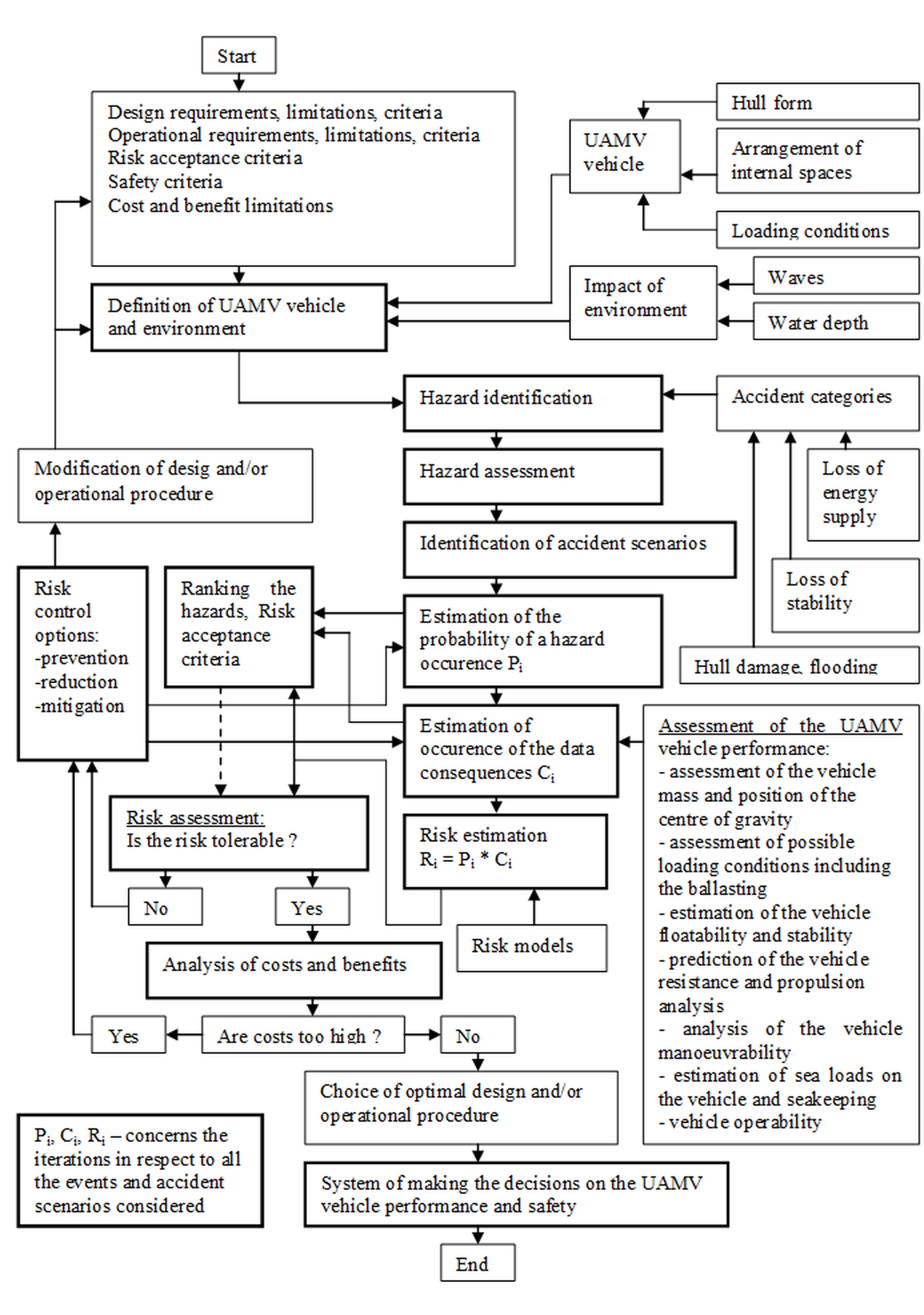
Fig. 3. A general structure of the method applied during the research and design process of the USV-WIG platform [9][16]
The research method presented in Figure 3 should enable to develop the USV-WIG platform solving the following fundamental problems in platform’s operation:
- definition of missions and development of event scenarios (sequences of events) related to application of the platform in real operational conditions,
- analysis of the platform performance and dynamics taking into account the missions,
- risk and safety assessment for defined mission scenarios,
- development of the operational procedures for the defined missions depending on the degree of platform autonomy.
As it was mentioned before the current stage of work related to development of the USV-WIG platform is focused on the analysis of the platform's performance and dynamics in conditions close to real ones.
The set of basic assumptions called functionalities related to development of the platform include as follows:
- implementation of tasks over the water areas and over the land close the coastline,
- carrying cargo and/or on-board equipment of a given mass,
- possibility of taking off from the water surface, flight for the data range and landing on the water surface,
- ability to fly at a minimum altitude of a few meters using the surface effect,
enabling testing of new technologies and design solutions in order to continue the project.
The most important research tasks related to development of the USV-WIG platform, which constitute a serious challenge for the teams of specialists representing the Consortium, include:
- development of the platform geometry in terms of good aerodynamic properties very important for any phase of platform’s operation (take off, flight, landing),
- development of the platform geometry in terms of good hydrodynamic features very important for any phase of platform’s operation but particularly for the take-off and landing phase,
- selection of construction materials, on-board systems (propulsion, power supply, sensors, efectors, control system, navigation and communication system) and platform deck equipment,
- estimation of the platform mass and center of mass position for loading conditions close to real ones,
- analysis of the platform payload, loads on platform’s structure and structural strength,
- analysis of the platform buoyancy and stability on the water surface (calm and rough sea),
- analysis of the platform resistance and propulsion properties for any phase of platform movement,
- analysis of the hydro-aerodynamic properties of the platform, taking into account the surface effect for all the phases: take-off, flight and landing,
- analysis of the aerodynamic properties of the platform, taking into account the surface effect, during the flight phase for a variable flight altitudes and trajectories (course keeping, turning, etc.),
- analysis of the platform dynamics,
- development and calibration of the control system,
- analysis of the impact of waves on the surface effect, platform’s dynamics and structure,
- construction of the platform demonstrator,
testing of the demonstrator in conditions close to real ones.
When developing the platform demonstrator various methods and technologies are used including among others:
- computer simulation at the stage of aerodynamic and hydrodynamic analysis,
- computer simulation during the analysis of the platform structure and strength,
- stand tests of the aerodynamic, hydrodynamic and structural-strength properties of the platform,
- development and bench tests of the on-board systems, including the propulsion and control systems,
- construction of the platform demonstrator,
- integration of on-board systems with the structure of platform demonstrator,
- tests of the platform demonstrator in open waters in conditions close to reality.[9] [10] [11] [12] [13] [14] [15] [16] [22] [23].
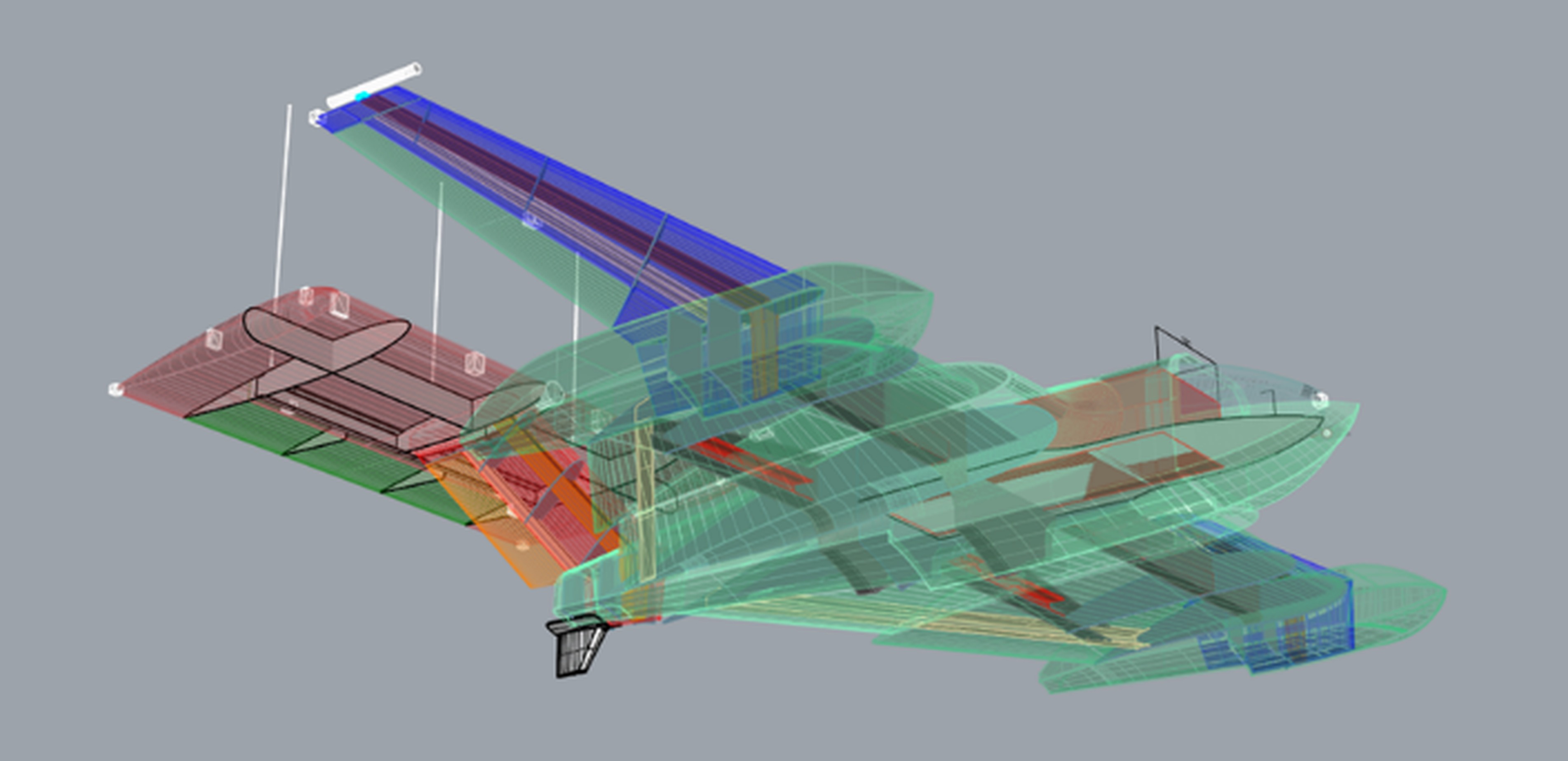
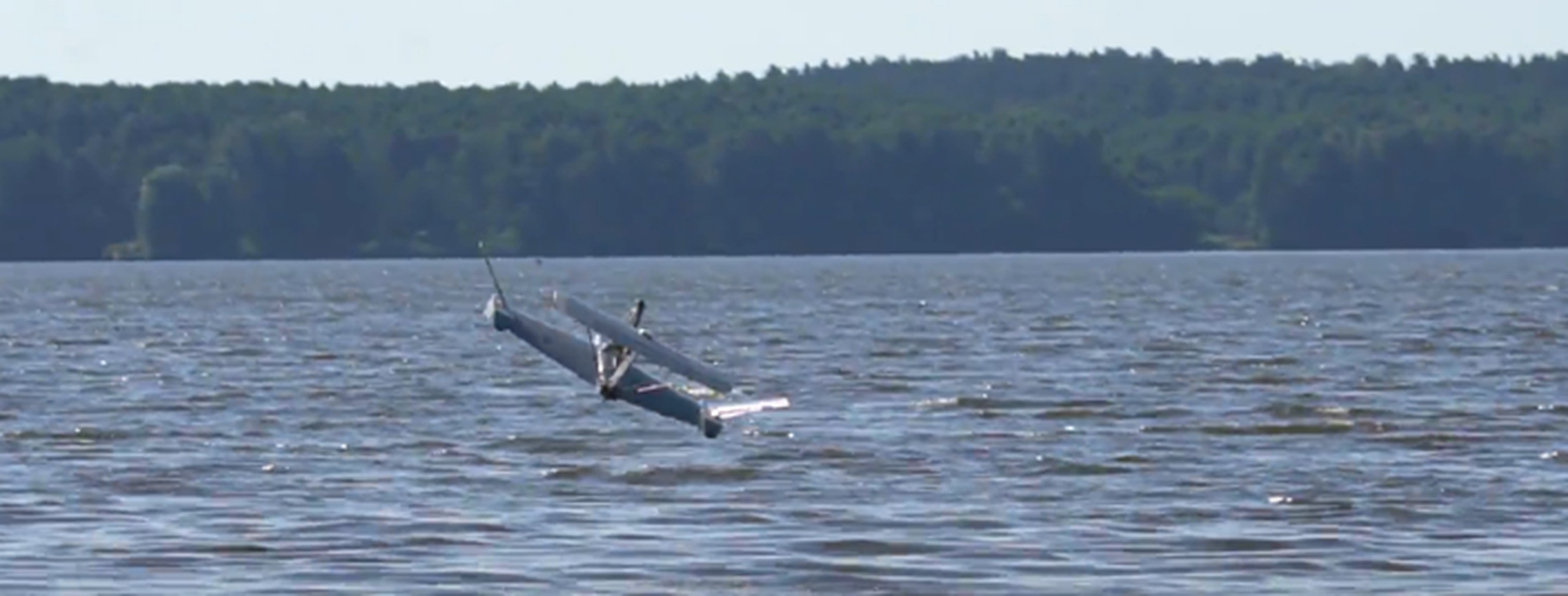
In Figure 4 a semi-final structure of the USV-WIG platform is presented [23]. In Figure 5 a photo is presented showing some elements of the open water test on dynamics of the USV/WIG unmanned scaled model made by the Military University of Technology [23].
. INITIAL ASSUMPTIONS FOR THE ANALYSIS OF AERO- HYDRODYNAMIC CHARACTERISTICS FOR THE USV-WIG PLATFORM DESIGN
The analysis of the USV/WIG platform dynamics concerned the determination of the aero-hydrodynamic characteristics of the platform for three phases of movement: take-off from the water surface, flight and landing on the water surface.
Take-off phase: The take-off phase requires to estimate some static and dynamical characteristics of the USV/WIG platform. Between them are the buoyancy, stability, resistance and propulsion and dynamics. The high variability of the aerodynamic lift forces and hydrodynamic forces including drag with increasing the platform speed is caused mainly due to the impacts following from the water-air loads on the platform structure. The speed range for this phase is measured from the initial stage of take-off to the speed when the platform is lifting off the free surface of water. Then, the flight begins [23].
An example of the transition of the platform-version-A from the take-off to the second phase of movement, flight, after it has detached from the free water surface is presented in Figure 6 [23].
Flight phase: The flight phase requires to estimate a few dynamical characteristics of the USV/WIG platform and control the flight by the lift forces generated on the foils. Flight height is estimated to be approximately 3 meters above the water level. The flight speed is assumed to be up to 100 km/h and the light range is equal to several kilometers. The flight phase characteristics are the stability and aerodynamic properties for the constant and variable distances of the platform from the water free surface under the influence of:
- changes in flight trajectory (proximity to land in the coastal zone, presence of water objects).
- external impacts followed from the wind and waves.
Dropping phase: applies to landing on the free water surface [23].
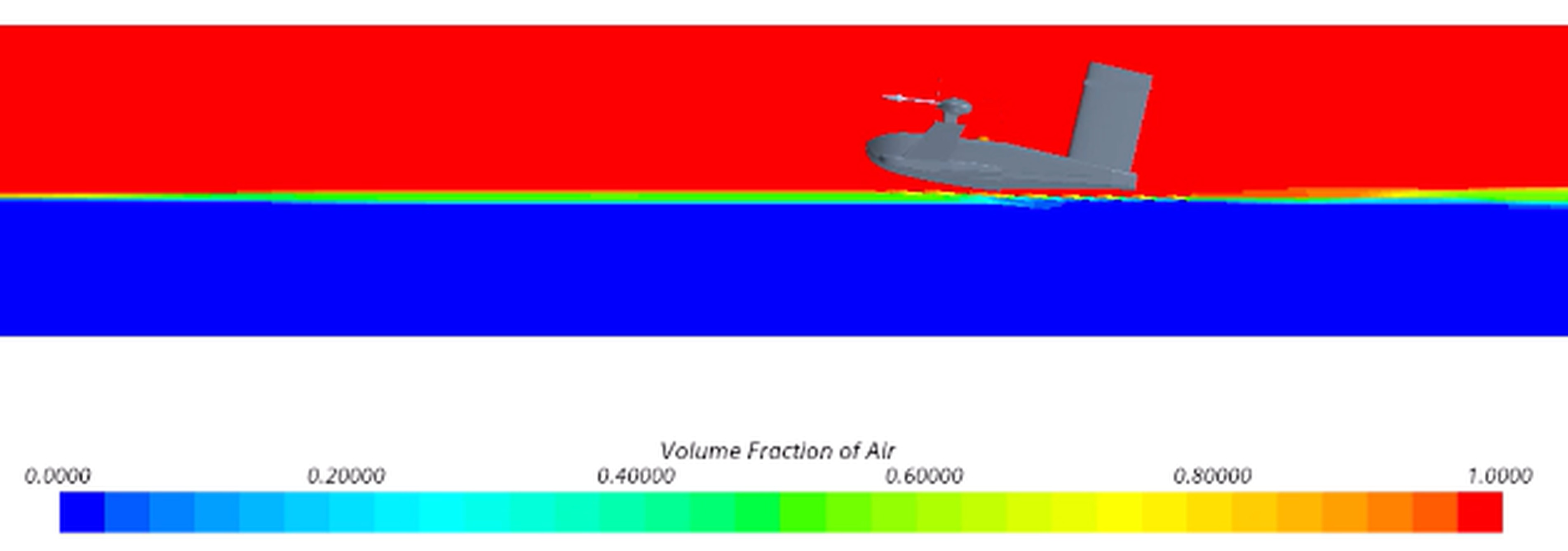
Fig. 6. Example of the transition of the platform-version-A to the second phase of movement, flight, after it has detached from the free water surface by Gdańsk University of Technology [23]
Landing phase: This phase requires to estimate all the previous static and dynamical characteristics of the USV/WIG platform. Sometimes this phase may be called the launching on a free water surface. For the landing the most important for the safety point of view are the operational conditions. At the current stage of design analysis it is assumed that the USV/WIG platform could be operated in conditions for the sea state below 2 degrees of Beaufort scale. The possibility of using the platform at higher sea states would require the minor changes to the platform's design, in particular in terms of the platform's propulsion system and hydrodynamic T-foils.
The platform should fly at a height of about 3 meters above the water level, also in wavy water (in waves). The analysis of the flight phase includes, among other things, determining the entire hull aerodynamic characteristics of the platform while maintaining a constant distance of the platform from the free water surface and when this distance changes as a result of external impacts (wind, waves). The behavior of the platform under the impact of external loads is difficult to predict. When the impacts occur in proximity of the land in the coastal zone or due to the presence of water-based objects (ships, offshore installations, yachts, etc.) the dynamics of the platform is a big challenge but it must be controlled by the control system.
The analysis of the platform dynamics was carried out assuming that the platform's maximum flight speed does not exceed 100 km/h (27.7 m/s) and the platform mass is to be about 300 kg.
At the construction stage of demonstrator the platform will be equipped with a propeller-driven combustion propulsion system and a remote control (RC), navigation and communication system. When the design is in progress close to implementation in real operational conditions the platform should operate in programmable, semi-autonomous or ultimately autonomous mode [23].
. SOME REMARKS ON PREDICTING THE DYNAMICS OF THE USV/WIG PLATFORM BY THE ADVANCED NUMERICAL FLUID MECHANICS TOOLS
From the analytical point of view the general set of equations of the UAMV vehicle moving on the water surface for the different phases of motion) may be presented as follwos [5] [6] [7] [8] [9] [17]:
where:
- i - index of the data component of the vehicle motion (i = 2,...,6),
- j - index of the data degree of freedom,
- Mij - vehicle mass matrix,ij - vehicle mass matrix,
- Aij - matrix of added masses,ij - matrix of added masses,
- Bij - matrix of dumping coefficients,ij - matrix of dumping coefficients,
- Cij - matrix of restoring coefficients,ij - matrix of restoring coefficients,
Fij - matrix of external hydrodynamic and aerodynamic forces.
At the current stage of research the following impacts have been taken into account: gravity forces, aerodynamic lift forces aerodynamic external loads, hydrodynamic restoring forces, hydrodynamic Froude-Krylov and diffraction forces, hydrodynamic slamming-based forces, hydrodynamic external loads, aero-hydrodynamic cushion forces (wing in ground forces), thrust forces.
The research and design of the USV/WIG platform was carried out in a standard procedure using the CFD calculations. There were five major tasks to perform during such the calculations, namely [23]:
Preparation of 3D platform geometry. It is advisable for it to be an associative model, where individual dimensions and/or mutual positions of the components are connected in a way that is desirable from the point of view of construction. Such a model allows you to easily create subsequent versions of the solid, thus enabling optimization research. In practice, this stage of work is usually handled by other teams and it was, so it is also important to be able to export the prepared solid with an appropriate extension, depending on the requirements of the software used. In Figure 7 the 3D platform geometry view is presented [23].
Selection of the computational domain. The geometry of the computational domain should be prepared in such a way that its boundary surfaces do not significantly affect the obtained results, thus providing an approximation of the unlimited domain. The most important dimension in the case of flow simulations is the distance of the outlet behind the tested surface, which is usually on the order of ten of the length of the tested object. The calculations were performed in the rectangular computational domain shown in Figure 8.[4] [22] [23].
Dividing the domain into finite volumes, i.e. creating the so-called computational grid. This is a very important stage of numerical calculations, because both the correctness of the obtained results and the computational time needed to carry out the simulation strongly depend on the quality of the prepared mesh. The search for a golden mean between minimizing the number of mesh elements due to the limitations of computational power on the one hand, and the size of the elements allowing the representation of the phenomena under study is achieved by condensing the mesh elements at critical points in the field, such as the free surface of the liquid and boundary layer at the surface of the object. Due to the type of calculations performed, allowing the release of individual degrees of freedom of the platform, an overset mesh dedicated to such the models was used [23].
Numerical simulations for all considered cases. Subsequent series of calculations were carried out, each time changing specific parameters, i.e. the geometry of the platform, its position relative to the free surface, the given speed and the adopted computational model (including the number of degrees of freedom of the platform). Each series allows to export the obtained calculation results necessary for further analysis [23].
Analysis of the results obtained and drawing conclusions - this is the last stage of work, summarizing the calculations performed, thanks to which it is possible to create guidelines for further design work of the unit. It assumes the assessment of the hydrodynamic properties of the platform, including the indication of the estimated demand for driving power necessary to overcome the resistance to the movement of the platform at the assumed forward speed. If the design goals are not achieved, the conclusions drawn from the calculations should also indicate the path to necessary changes introduced in the platform design, and thus repeat the so-called design spiral.[23].
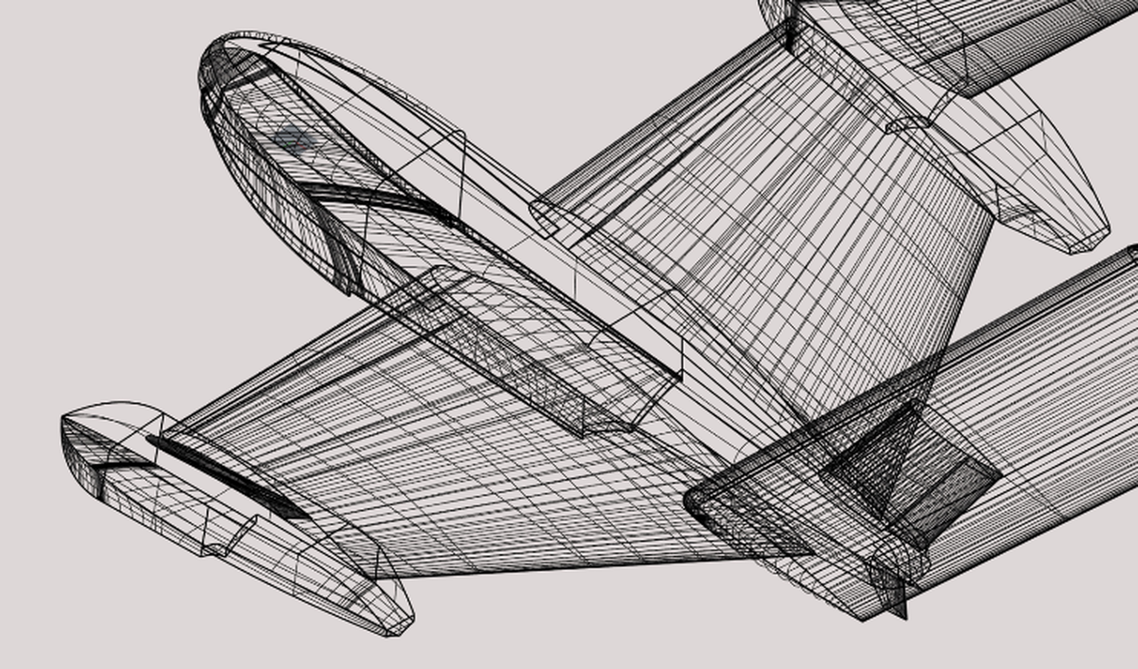
Fig. 7. An example of the 3D USV/WIG platform geometry view by Gdańsk University of Technology, Military University of Technology, Air Force Institute of Technology [23]
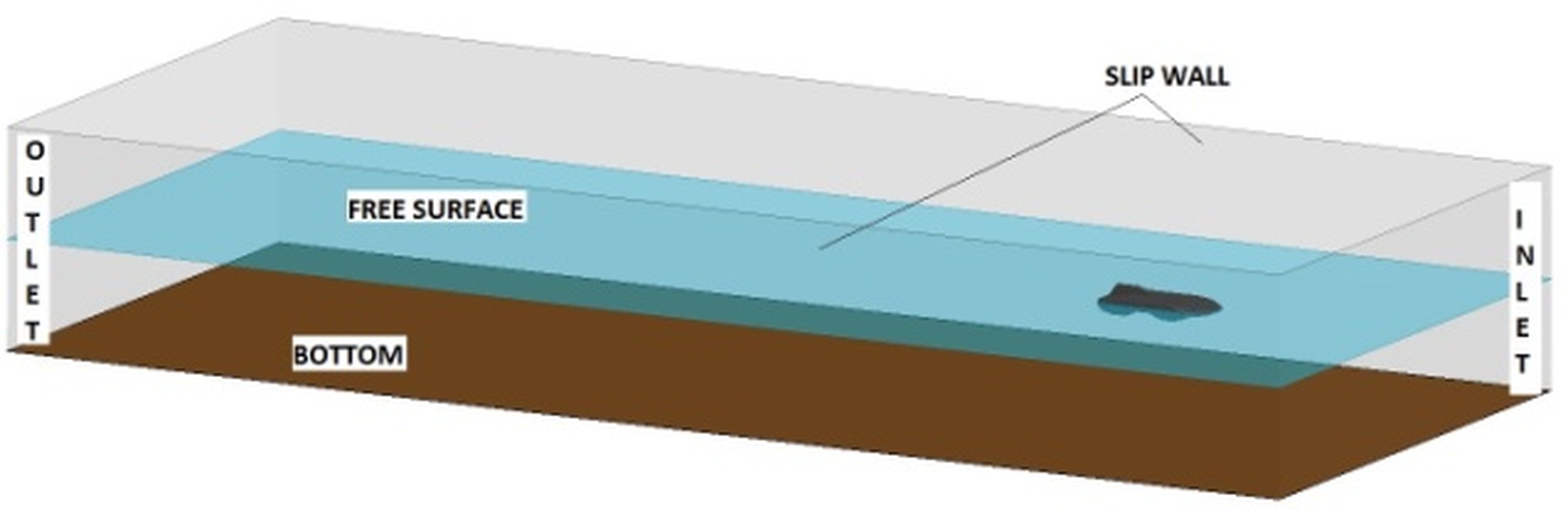
Fig. 8. T he 3D view of the rectangular computational domain used during the USV/WIG platform design using the CFD calculations, by Gdańsk University of Technology [23]
The numerical simulations of the USV/WIG platform motion were performed using the STAR CCM+ program using the advanced calculation modules. The platform was modeled as a rigid body with six degrees of freedom. Its mass, center of gravity position and moments of inertia are modeled. The thrust force was given as a vector attached to the structure at the propeller attachment point, the direction of which changes with the platform's motion, and the value is constant or depends on the selected variables. The elevator's foil action was modeled as an additional force applied, the value of which was given as a function of the platform's speed and position, which allows modeling the platform's motion in the basic phases (takeoff, flight, landing) [23].
The modeling of the platform's motion was possible by using the Dynamic Fluid Body Interaction (DFBI) model and use of the moving overset meshes. The two-phase environment was modeled using the Volume of Fluid (VOF) model extended with the wave models [23].
Currently, during the numerical simulations of aero-hydrodynamical phenomena the fluids flow modeling is used using the Computational Fluid Dynamics (CFD) based on solving the averaged Navier Stokes (Reynolds-averaged Navier–Stokes) equations describing the turbulent flow of a viscous fluid with consideration of the free surface of water. Equations describing the principles of conservation of mass, momentum and energy have been written in a time-averaged manner. Their solution is realized by the FVM method (finite volume method), which directly discretizes the equations, i.e. converts the system of differential equations into a system of algebraic equations [23].
The prediction of the platform’s performance was realized with the use of numerical model based on the CFD techniques coupled with the 6DOF motion module. To strengthen the accuracy of prediction the platform’s dynamics a computational method, based on the CFD solver allowing simulating the platform’s dynamics in waves was elaborated. Such the method may be characterized by the following features [23]:
- direct simulation of the forces exerted by the water on the platform’s hull,
- as a consequence of the above, there is no need to estimate or calibrate the added masses coefficients, damping coefficients etc.,
- there is a possibility of visualization and quantitative assessment of all the processes caused by the water and air flows.
During the USV/WIG platform design the computer-based simulations were carried out using the interpenetrating grids, simultaneously describing the platform's motion using a model implemented in the program, with particular consideration of the platform’s pitch and heave.
A structure of all the stages connected with numerical modelling and calculations of the platform’s dynamics by the advanced CFD tool is presented in Fig. 9 [23]. These are the subsequent stages of numerical modeling of the platform's dynamics (motion).
The basic features of the method for evaluation the USV/WIG platform dynamics (calculations of the platform’s dynamics) may be described by the following components applied [22] [23]:
- method is using the CFD algorithm based on solving the RANSE equations,
- method is implicit unsteady,
- method enables to apply the VOF (Volume of Fluid) to consider the platform’s dynamics in waves,
- method enables considering the gravity impacts,
- method is using the k- epsilon turbulence model to characterize the phenomena and flow,
- method enables to consider the multiphase interactions,
- method enables to use the DFBI (Dynamic Fluid Body Interaction) model.
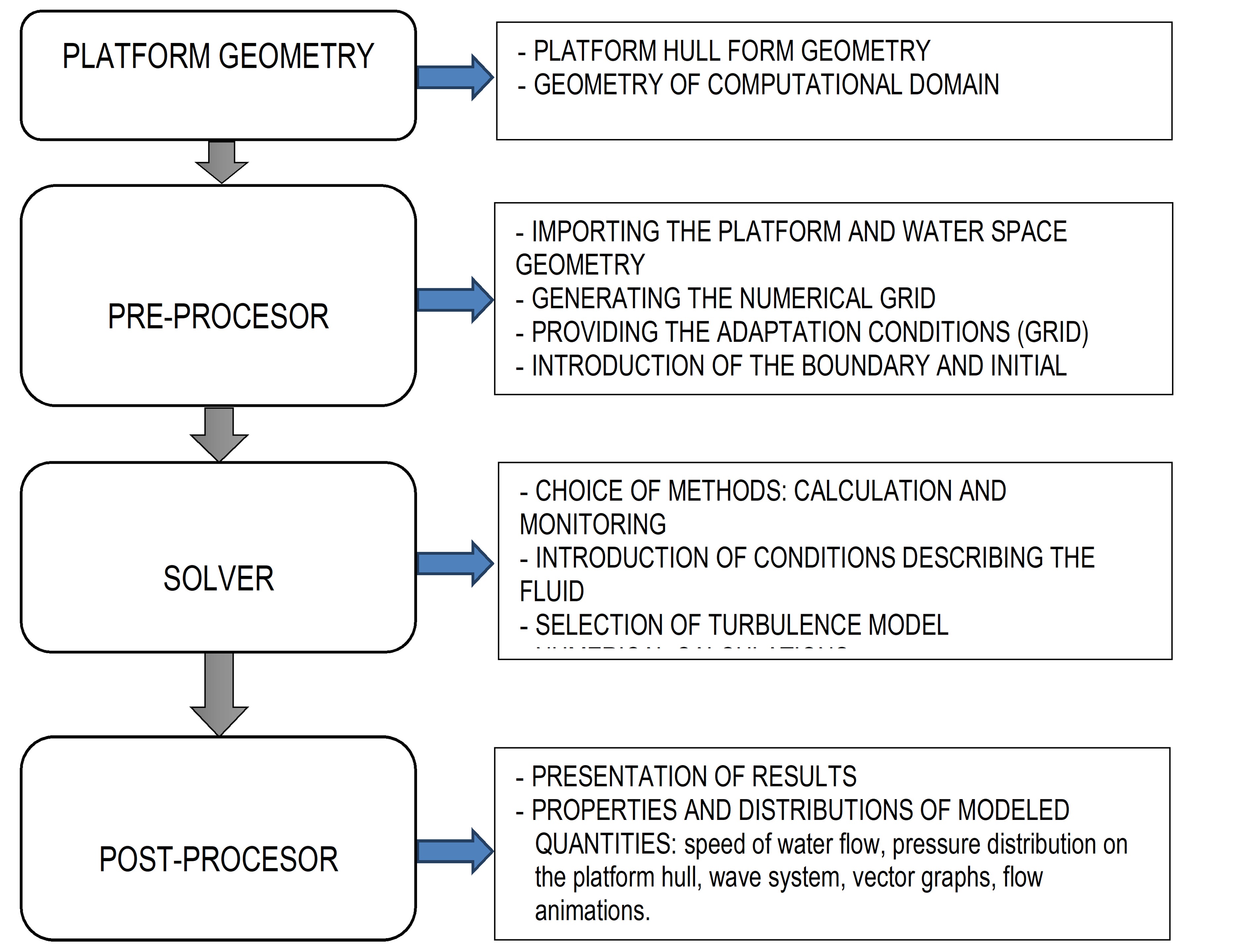
Fig. 9. A structure of all the stages connected with numerical modelling and calculations of the platform’s dynamics by the advanced CFD tool, by Gdańsk University of Technology [23]
The most important features of the simulation model used are as follows [22] [23]:
- the computational domain is divided into two areas: a stationary area, in which the flow parameters are given (initial velocity and undulation) and a moving area, surrounding the platform and moving with it,
DFBI (Dynamic Fluid Body Interaction) model: allows to model the dynamic reactions of the fluid on the platform and the platform on the fluid, treating the platform as a rigid body with specific parameters: mass, center of gravity position, moments of inertia, initial velocity and applied external forces which do not have to be constant but can be given as functions depending on the given parameters (vehicle tilt angle, its speed, wetted surface area, etc.)
VoF (Volume of Fluid) model: allows to model two-phase flow (water-air) by calculating the percentage share of each fraction in the control volumes, the fluids filling the domain are treated as a single fluid and additional variable is introduced for each of the components: the “volume fraction”; the parameters of the resulting multiphase fluid (e.g. density) are then computed as follows: ρ = iρici, where: ρi – is the density for each of the components, ci – is the volume fraction for each of the components, respectively. Note that ici= 1 in each point of the domain,
- wave model: allows to model the wave in the computational domain by determining the fluid velocity, fraction volume and hydrostatic pressure for piles with given parameters,
- overset mesh (overlaid meshes): allows to model the movement of the object within the stationary domain.
If the aero-hydrodynamic forces acting on the platform are balanced, the platform will remain stationary. This is the first stage of calculations, i.e. determining the equilibrium position. Then, as an example, a thrust force is applied, which causes the platform to move. The platform speed is added to the initial speed specified in the domain, and the resultant platform speed is thus determined. During the calculations, the platform's trajectory and the forces acting on it (loads) are recorded [22] [23].
. ANALYSIS OF THE AERO-HYDRODYNAMIC CHARACTERISTICS OF THE USV/WIG PLATFORM BY THE CFD TOOLS
The analysis of the aero-hydrodynamic characteristics has been performed by application of the iterative approach in the following way [23]:
- definition of the platform geometry by the Military University of Technology,
- estimation of the aerodynamic forces on the platform structure by the Military University of Technology,
- estimation of the combined the aero-hydrodynamic forces on the platform structure by the Gdańsk University of Technology,
- checking the design and operational criteria from the platform’s functionality, performance and safety point of view.
After improving the platform from the requirements point of view concerning the geometry, aerodynamics, hydrodynamics, materials, structure, construction and strength and functionality the performance and safety assessment has been estimated with special regards to platform’s dynamics.
It should be underlined again and again that a good design of the USV/WIG platform requires to obtain a proper behavior of the platform for the take-off, flight and landing phases. Prediction of the aero-hydrodynamic characteristics is a key design factor deciding about the platform dynamics. A good platform dynamics and well analyzed knowledge base of the aero-hydrodynamic characteristics will enable to work out and built a USV/WIG platform control system [23].
. USV/WIG platform dynamics during the take-off phase
During the preliminary design and having all the data concerning the platform geometry, materials, structure, construction and strength and functionality (position of the center of mass, propulsion system including the engine thrust) the first attempts to take the platform off the water were not successful. The platform did not lift off, pitch was decreasing, bow part of the platform was trimmed and immersed under the water surface. The platform final position during the first unsuccessful take-off phase is presented in Figure 10 [23].
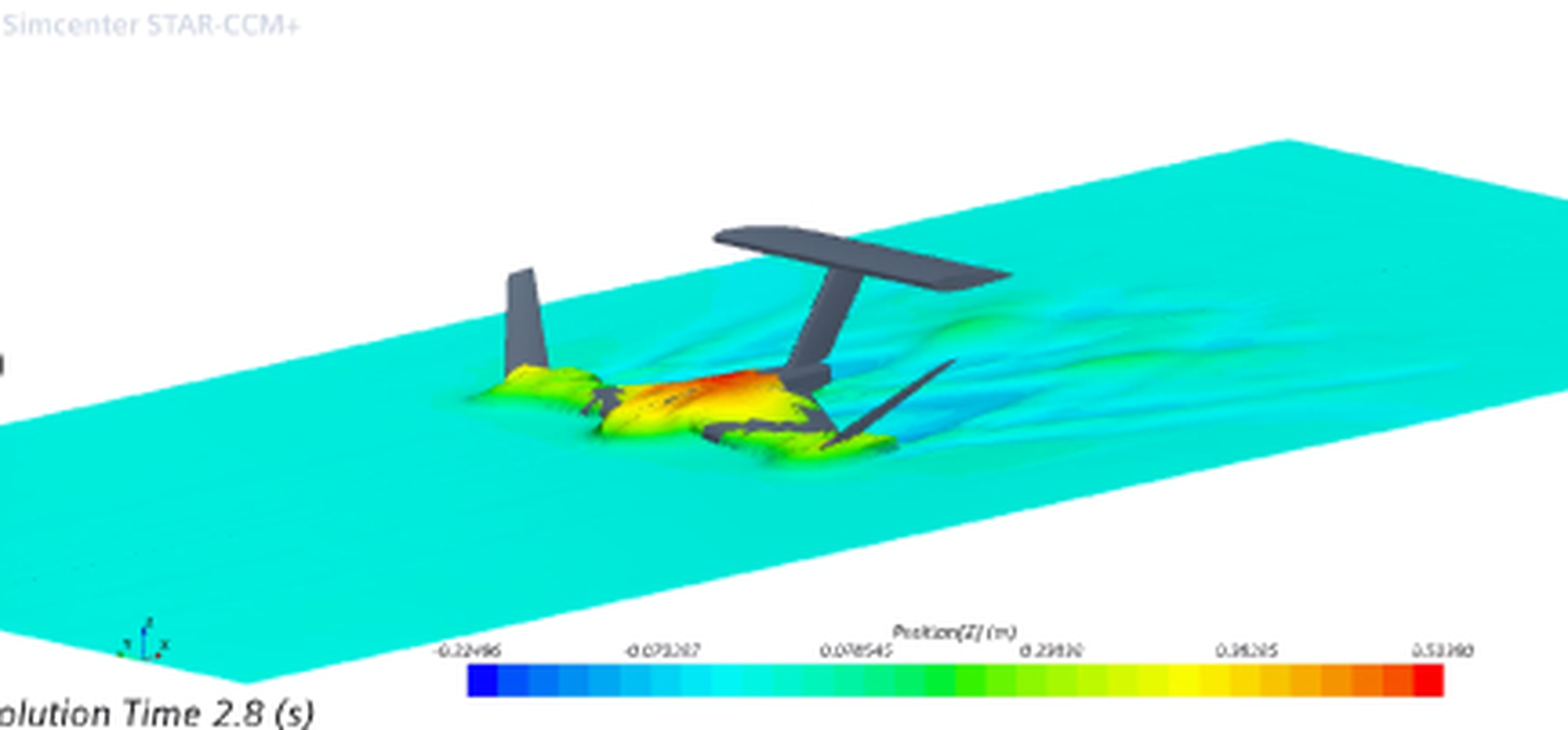
Fig. 10. The USV/WIG platform final position during the first unsuccessful take-off phase using the advanced CFD tool, by the Gdańsk University of Technology [23]
The design changes were introduced and they concerned as follows:
- changing the longitudinal position of the center of gravity backwards,
- changing the aerodynamic moment by deflecting the aileron foil upwards to obtain the downward acting aileron aerodynamic force.
The above changes enabled to obtain a positive additional value of the aero-hydrodynamic momentum.
From the practical point of view the proposed solutions should change the platform dynamics during the take-off phase by obtaining the aerodynamic downforce at the stern due to deflecting the elevator foil upwards. It is important to know that during the take-off at a low platform speed the forces generated on the each foil working in the air are too small and increasing its angle of attack is an ineffective solution. Shifting the platform’s center of gravity backwards, towards the stern, seems to be an effective solution. The changing of the longitudinal position of the center of gravity backwards and changing the aerodynamic moment by deflecting the aileron foil upwards is presented in Figure 11 [23].
Then a simulation was performed many times again and the platform given the same initial speed as it was in previous simulations and finally the platform did the take-off and left the water. In Figure 12 the first take-off phase of the USV/WIG platform is presented [23].
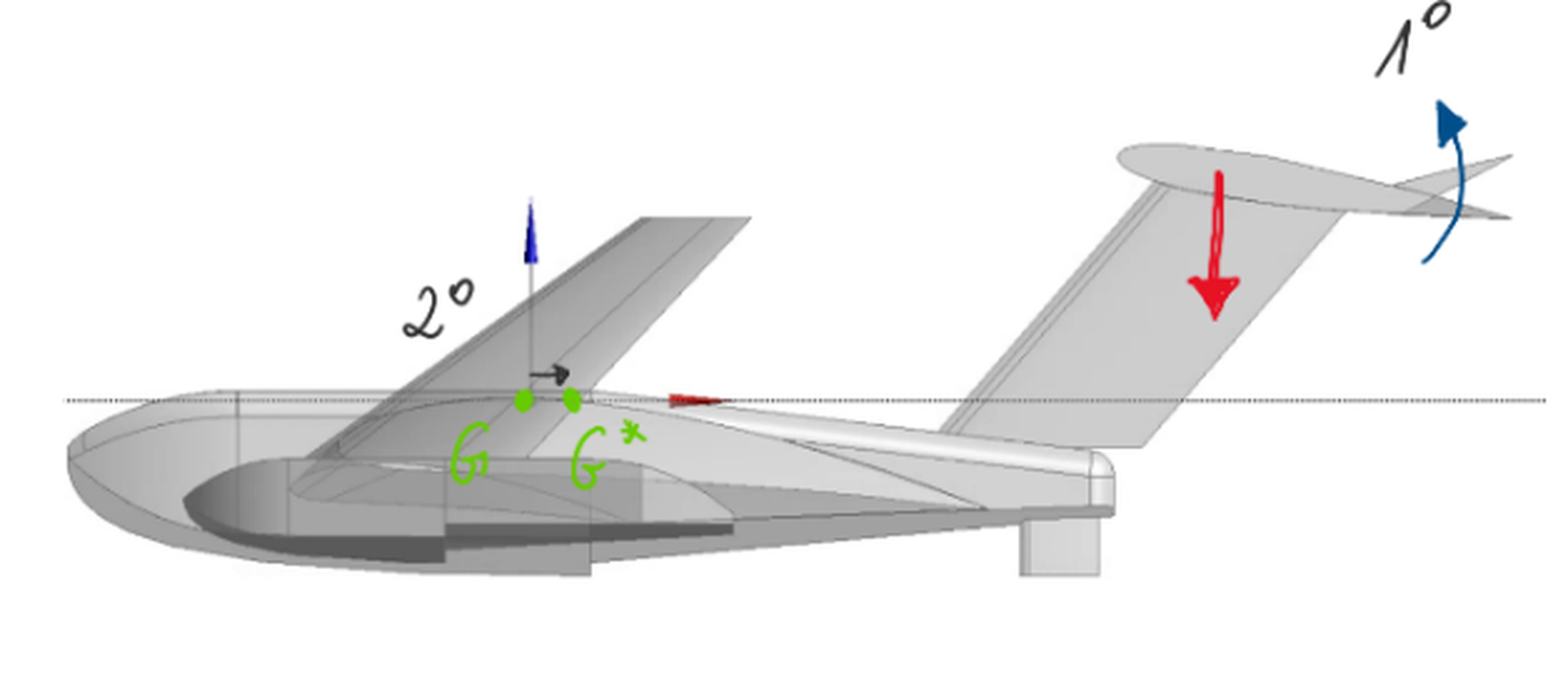
Fig. 11. The changing of the longitudinal position of the center of gravity backwards and changing the aerodynamic moment by deflecting the aileron foil upwards, by the Gdańsk University of Technology [23]
After the take-off the platform started to speed up as the same thrust started to become bigger than the platform’s resistance in the air. But, the new problems appeared. The aerodynamic momentum has been to big and the pitch value started to increase. The platform started the parabolic trajectory upwards.
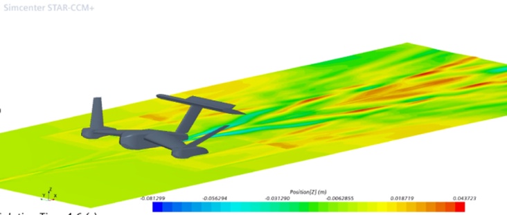
Fig. 12. The first take-off of the USV/WIG platform using the advanced CFD tool, by the Gdańsk University of Technology [23]
In such the way the next problem appeared how to stabilize the flight and how to reach the functional altitude of flight. Between the questions one was the most important one: Will it be possible to stabilize the platform flight?
. USV/WIG platform dynamics during the flight
The flight stabilization simplified control model was prepared. To avoid the platform’s parabolic trajectory upwards a criteria was set up to keep the pitch angle no greater than 10 degrees from the quasi-static horizontal position of the platform. Deflecting the elevator aileron downwards it was possible to generate the additional lift force (upwards) on the elevator foil-aileron which allowed the platform to stabilize its flight. The process of stabilizing the flight as the sequence of the elevator lift force action is presented in Figure 13 [23].
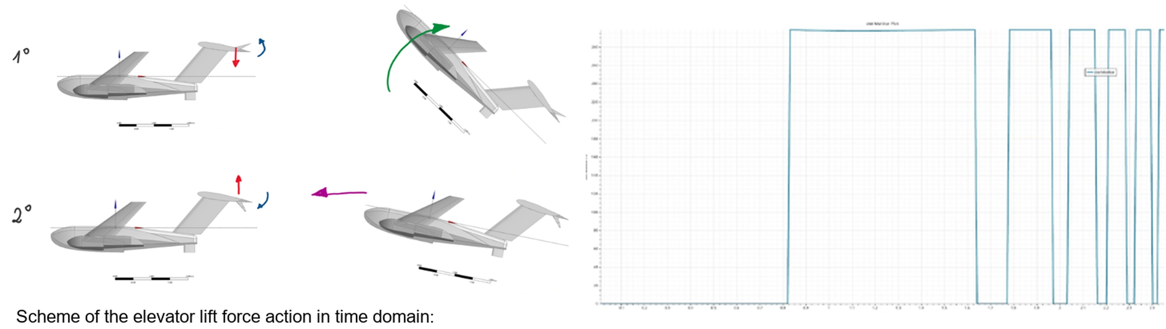
Fig. 13. The process of stabilizing the flight as the sequence of the elevator lift force action, by the Gdańsk University of Technology [23]
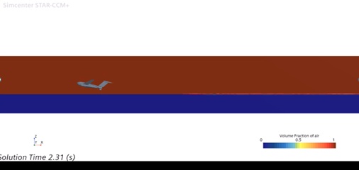
Several tests performed with the flight stabilization procedure confirmed the procedure to be successful. The platform was able to move with the altitude about 1 meter above the water surface by controlling the flight using the elevator lift force action. The flight of the platform with the altitude about 1 meter above the water surface is presented in Figure 14 [23].
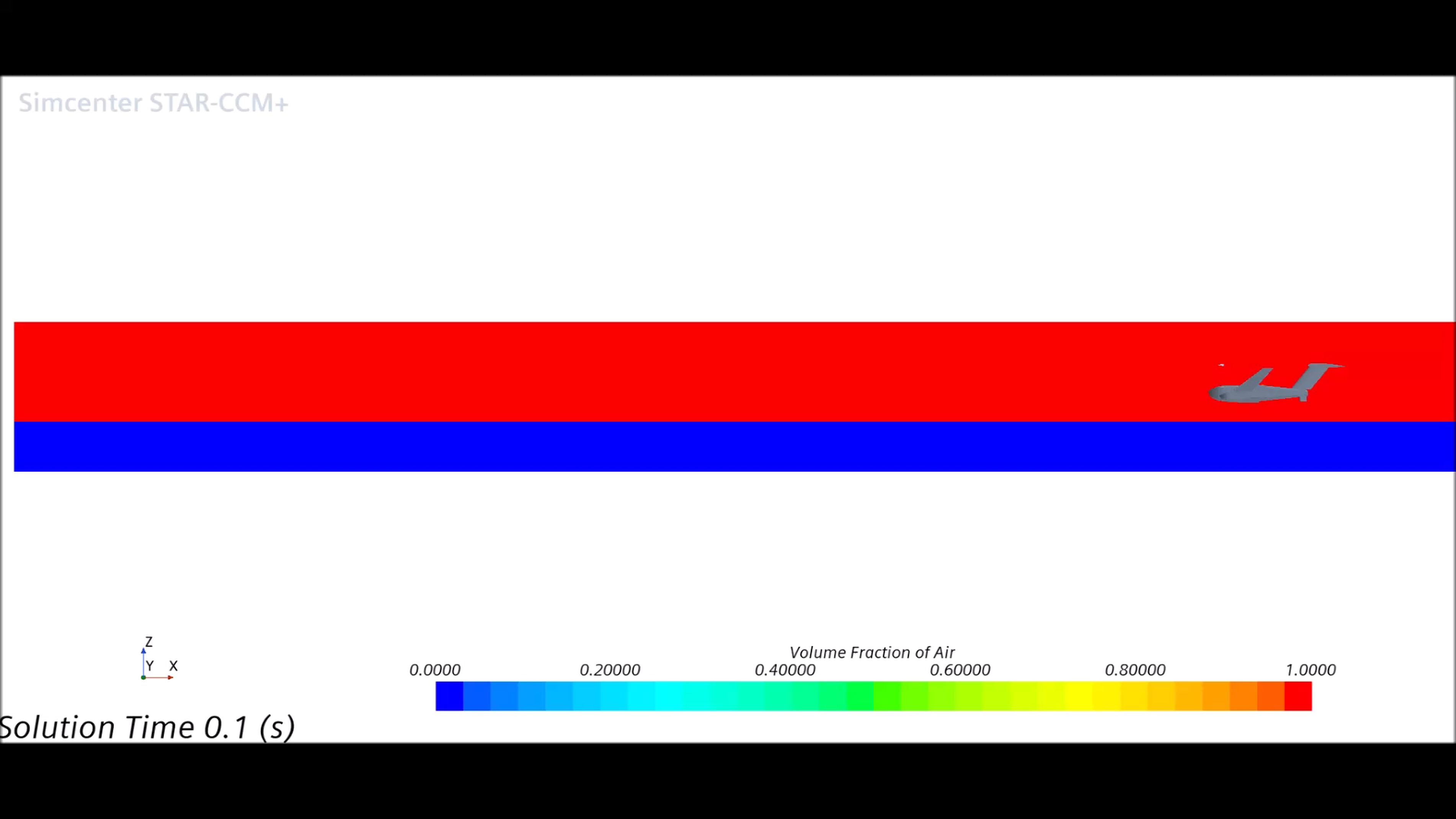
Fig. 14. The flight of the platform with the altitude about 1 meter above the water surface, using the advanced CFD tool, by the Gdańsk University of Technology [23]
The presented platform dynamics during the flight confirmed that the platform is able to fly and that there is an open way to start the design of the platform control system.
Then the next problems were solved. A slightly more complex control function was given to model the transition from take-off to direct stabilized flight. During take-off, when the platform still contacts the water, the elevator aileron is deflected upwards, providing a downforce on the stern, allowing the platform to take off, then, as the hull wetted surface of the platform decreases, the elevator maintains the platform’s position at a 10-degrees elevator aileron deflection with the platform’s nose up.
After lift-off during the flight, the thrust force is slightly reduced as a response to the reduced platform drag. The procedure of maintaining a constant platform speed, speeding up and slowing down the platform will last between the most important problems to be considered before the operational procedures will be prepared.
. USV/WIG platform dynamics during landing
First case of landing: thrust off – landing with no control. In the first attempt to model just before the platform landing both the forces the thrust and elevator aileron force were turned off. This caused the platform to increase its pitch and platform started the uncontrolled parabolic style trajectory like during the primary take-off computer-simulated test. This is the first case of landing when the thrust is off and there is no control using the elevator aileron generated lift force. This case is presented in Figure 15 [23].
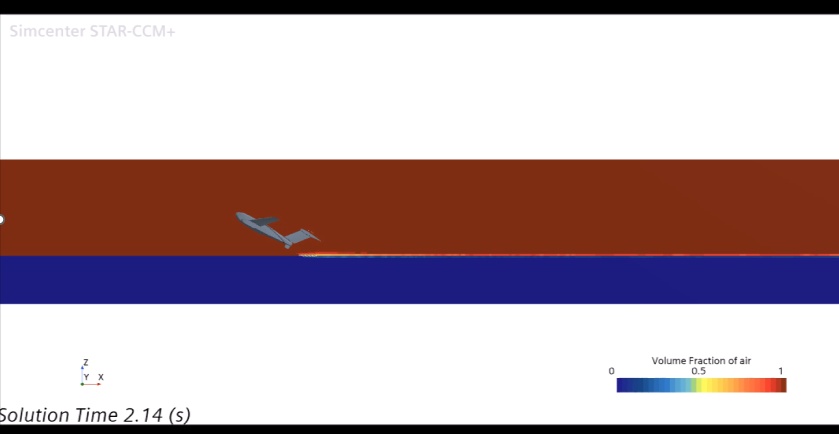
Fig. 15. The first case of landing when the thrust is off and there is no control using the elevator aileron generated lift force, using the advanced CFD tool, by the Gdańsk University of Technology [23]
First case of landing: thrust off - landing with control. In the second attempt during the landing, only the thrust was turned off leaving the elevator in operation. Such the approach to landing caused the platform landed gently on the water surface and gradually lose the speed. So, this is the second case of landing considered when the thrust is off and there is a constant control using the elevator aileron generated lift force. This case is presented in Figure 16 [23].
. SUMMARY
The first stage of the presented research project has been completed. The entire period of the research, design and implementation work will last 36 months. The fundamental problems related to the design of the platform demonstrator include the development of an integrated aero-hydrodynamic hull form of the platform, its structure including the detailed structural and technological solutions, and the construction stage. The key problems from the point of view of the platform's performance and dynamics include the buoyancy and stability of the platform and its aero-hydrodynamic properties in all phases of movement, under the influence of the wind and/or wave excitations. The culmination of the planned work will be testing the platform in conditions close to operational reality.
The research method was based on the analysis of the platform mission consisting of the specific event scenarios, analysis of the platform's performance and dynamics for the defined missions, and risk and safety assessment of the platform’s missions. The above approach is the basis for development of the control system and operational procedures.
The results of the research to date constitute the developed mission scenarios. An integrated aero-hydrodynamic geometry of the platform's hull was developed. An analysis of the platform's aero-hydrodynamic characteristics and dynamics was carried out for the given phases of platform movement, taking into account the operation of the propulsion system.
During the work to date, including the analysis of the platform's aero-hydrodynamic characteristics, the following methods were used. parametric studies, CFD computer-based simulations, FEM computer-based simulations, platform’s aero-hydrodynamic performance, risk and safety assessment.
The key achievements at the current stage of the project include:
- The platform design method was developed, including the functional features, performance and safety.
- The main dimensions, hull form and arrangement of internal spaces.
- The analysis of several variants of the platform's aero-hydrodynamic system was carried out. The parameters and characteristics of the critical technology: the near-surface effect were determined.
- A few variants of the platform's construction were developed, with the indication of optimal solutions.
- The structural and strength analysis of a few variants of the platform's construction was carried out.
- The concept for the platform's navigation and control system was developed, and bench tests were performed.
- The concept of the communication system with the platform's ground and avionic systems was developed, and bench tests were performed.
- The further steps of project concern the executive design, platform construction and platform testing conditions close to reality.