
INTRODUCTION
Economizers are widely recognized as an essential component of modern boiler systems, where they serve to recover waste heat from flue gases and thereby increase overall thermal efficiency. Their historical development dates back to the nineteenth century, when growing industrial demand for improved fuel utilization motivated the introduction of tubular heat exchangers into steam boiler installations. Contemporary economizers, however, have evolved into sophisticated units employing advanced materials, optimized geometries, and integrated control strategies to meet increasingly stringent energy-efficiency and emission standards. The relevance of waste-heat recovery in biomass and solid-fuel boilers has been consistently highlighted in recent research, particularly in the context of reducing fuel consumption and mitigating greenhouse gas emissions.
Recent studies emphasize that the performance of economizers strongly depends on the characteristics of the combustion process and the quality of the fuel supplied. Junga et al. (2017) [1] demonstrated that small biomass boilers exhibit considerable variability in efficiency and pollutant emissions when alternative fuels such as sewage-sludge-based pellets or agricultural-waste blends are used. Their findings indicated that unstable combustion and elevated CO and NOx emissions may occur unless the boiler is supported by improved air-distribution control and heat-exchanger modifications. Similarly, investigations into co-combustion strategies have revealed additional challenges. Junga et al. (2025) [2] showed that introducing thermolysis char from waste rubber into straw-based fuels can maintain acceptable boiler efficiency but leads to increased particulate deposition and risks of slagging or corrosion. These observations collectively demonstrate that stable heat recovery requires not only enhanced combustion control but also heat-exchanger designs resistant to fouling and conducive to uniform flue-gas flow.
Advances in economizer technology focus increasingly on the optimization of heat-transfer structures. Numerical and experimental studies show that improved flue-gas routing and redesigned finned-tube or spiral exchangers can significantly reduce exhaust temperature and fuel losses. Behzadi and Abbasian Arani (2025) [3] reported that modifying flow patterns in economizer channels improves thermal performance and reduces operating fuel demand in high-pressure boilers. Complementary work by Chantasiriwan (2021) [4] demonstrated that combining economizers with air heaters or flue-gas dryers yields cost-effective increases in heat-recovery efficiency for biomass boilers. Further progress in numerical modeling, as shown by Behzadi et al. (2025) [5], confirms that proper tube spacing and ash-deposit considerations are crucial for maintaining heat-transfer effectiveness in industrial water-tube economizers.
A growing body of research also explores the influence of fuel additives on heat-transfer processes. Junga et al. (2020) [6] demonstrated that liquid fuel additives can lower ignition temperature, modify combustion kinetics, and reduce flue-gas losses in small and industrial coal boilers, leading to efficiency gains of up to 2.5 percentage points. Their work highlights that even modest improvements in combustion conditions can significantly enhance waste-heat recovery potential. In parallel, studies by Kornienko et al. (2025) [7] examined deep heat recovery in condensing economizers and identified how acid condensation, particulate fouling, and low-temperature corrosion interact with heat-transfer surfaces. Insights on humidified and condensing economizers from Salehipour et al. (2024) [8] show that enhanced moisture content in the gas stream intensifies latent-heat recovery and raises water-side temperature lift. Despite these advances, several persistent challenges remain. Economizers must operate reliably under conditions involving variable flue-gas composition, ash deposition, and condensation of water vapor particularly relevant in biomass boilers, where fuel moisture and hydrogen content determine latent-heat availability. Tang et al. (2021) [9] and Xiao et al. (2019) [10] underline the importance of structural optimization and active flue-gas temperature control to ensure stable performance and prevent corrosion or deposit-induced degradation. These studies collectively identify a clear research gap: the need for compact, corrosion-resistant economizers capable of maintaining high heat-recovery efficiency under biomass-specific operating conditions and variable thermal loads.
Given the relatively low sulfur content of biomass fuels, condensing economizers offer a promising opportunity to capture latent heat with minimal risk of acid-induced corrosion. However, practical implementation requires a design that ensures stable condensation, effective transfer of latent and sensible heat, and minimized fouling across the tube bundle. Addressing this gap, the present study introduces and experimentally validates a novel condensing economizer (Patent No. PL247342B1) designed for small and medium-scale biomass boilers. The unit integrates a counterflow–crossflow heat-exchange configuration with a centrally distributed flue-gas chamber and a water-cooled tube bundle. Analytical modeling is combined with experimental evaluation on pellet boilers with nominal outputs of 25–100 kW to assess thermal performance, condensate formation, and emission behavior. The goal of the study is to quantify the efficiency gains achievable under real operating conditions and to demonstrate that the proposed monoblock economizer architecture can substantially enhance waste-heat recovery while ensuring low emissions and stable system operation.
ECONOMIZER CONSTRUCTION
Excessively high flue-gas temperatures representing a direct source of thermal losses are frequently encountered during the operation of biomass-fired heating boilers. Such conditions typically arise from oversizing the heating installation relative to the actual thermal demand, selecting a boiler inadequately matched to the system, or from short-term thermal surges caused by combustion of an excessive amount of biomass fuel.
The economizer developed in this study is based on a shell-and-tube heat exchanger configuration. Flue gases are directed through the shell side due to their lower specific volume compared with the water circulating on the tube side, which allows for a more compact gas passage and favorable flow distribution across the bundle. The water flows inside the tubes, ensuring controlled hydraulic conditions and effective removal of the recovered heat.
The tube bundle consists of forty-two straight tubes made of corrosion-resistant stainless steel, selected to ensure durability under condensing conditions and exposure to acidic condensate. Each tube has an outer diameter of 12 mm, an inner diameter of 10 mm, and a wall thickness of 1.0 mm. The active length of each tube is 600 mm. These dimensions were chosen as a compromise between mechanical strength, hydraulic resistance on the water side, and enhanced external heat transfer under crossflow gas conditions.
The tubes are arranged in a staggered configuration in order to intensify turbulence in the flue-gas stream and increase the effective convective heat transfer coefficient. The transverse (lateral) pitch of the bundle is 18 mm (Pt/do = 1.5), while the longitudinal pitch is 20 mm (Pl/do ≈ 1.67). Such spacing ensures sufficient flow acceleration between adjacent tubes while preventing excessive pressure drop and minimizing the risk of ash bridging or fouling under biomass combustion conditions. The adopted pitch-to-diameter ratios are consistent with recommended design practice for compact gas–liquid heat exchangers operating under moderate Reynolds numbers.
Water flows in parallel through six tubes in each row, and the flow is subsequently redirected between successive rows by means of partition plates integrated into the header section.
To ensure uniform distribution of the water flow across the tube bundle, particular attention was paid to the hydraulic design of the inlet and outlet manifolds. The economizer is equipped with a symmetrical supply and return collector system, in which the inlet header distributes water evenly to all parallel flow paths. The geometry of the collectors was designed to maintain identical hydraulic lengths for each individual flow circuit, thereby minimizing the risk of preferential flow in selected tubes. All tubes have identical inner diameters and equal active lengths, which ensures equal hydraulic resistance under steady operating conditions. The total water flow rate through the economizer was continuously monitored using an electromagnetic flowmeter installed in the main supply line. Although individual tube flow rates were not measured separately, the symmetry of the hydraulic layout, combined with identical geometric parameters of all flow paths, provides a uniform pressure drop across each tube. This design approach is consistent with standard engineering practice for compact parallel-flow heat exchangers. During experimental operation, the water flow rate was regulated to maintain a constant temperature difference between the supply and return lines at ΔT = 25°C (±2°C). Stable maintenance of this temperature difference throughout the measurement series confirmed steady thermal behavior and indicated the absence of significant flow maldistribution within the bundle. No temperature oscillations or localized overheating were observed, which further supports the assumption of uniform flow distribution.
This arrangement provides uniform flow distribution and maintains comparable velocity in each flow path, reducing the risk of local overheating or uneven condensation intensity. The multi-pass internal configuration also increases the effective water-side heat transfer coefficient while maintaining acceptable hydraulic losses.
The entire tube bundle is mounted between two sieve plates ensuring precise tube positioning and structural rigidity. The assembly is enclosed within a rectangular housing that facilitates easy access for inspection and cleaning of the external tube surfaces. The housing geometry additionally promotes relatively uniform flue-gas distribution over the frontal area of the bundle, thereby supporting stable condensation and repeatable thermal performance.
The structural frame of the economizer is a box-type construction composed of bent, bolted, and welded sheet-metal components. This modular design enables disassembly of the flue-gas chamber and efficient removal of accumulated particulate deposits. Two flue-gas nozzles connect the economizer to the boiler outlet and the chimney duct. Heat recovery and water-vapor condensation occur within the tube bundle, where the cooled exhaust gases transfer both sensible and latent heat to the circulating water.
The economizer functions as a counterflow heat exchanger, with the flue-gas stream moving in the opposite direction to the water inside the tubes. This configuration enhances the overall heat-transfer effectiveness. Additionally, the water flow within the tube bundle forms a crossflow arrangement relative to the gas stream, further intensifying heat exchange and increasing the degree of moisture condensation. A representative design of the economizer is shown in Figs. 1 and 2 [11].
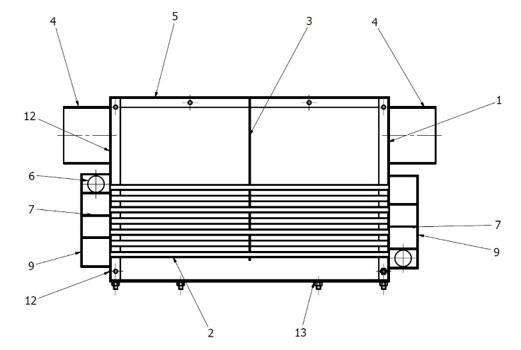
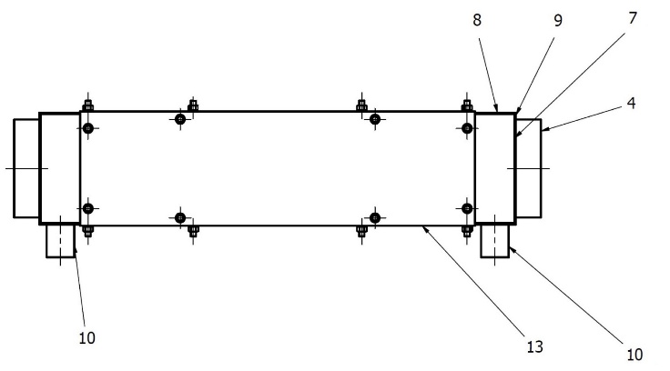
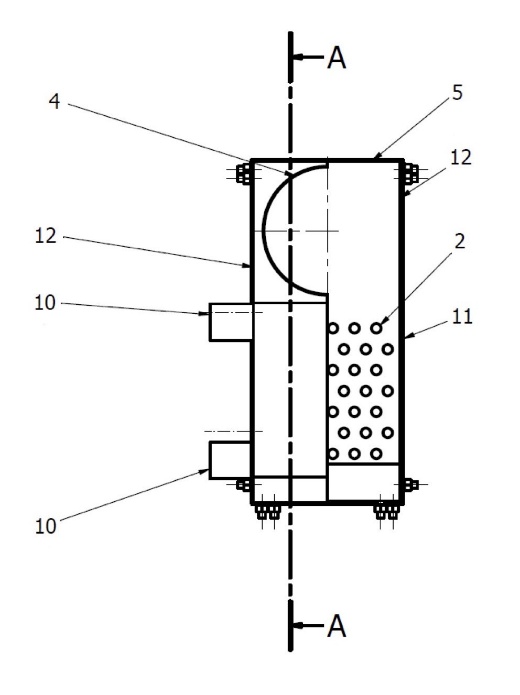
where: 1 – right sieve plate, 2 – screen tube, 3 – middle sieve plate, 4 – flue gas connection, 5 – top cover, 6 – front side cover, 7 – partition, 8 – rear side cover, 9 – front cover, 10 – supply connector, 11 – inspection and cleaning side cover, 12 – left sieve plate, 13 – bottom cover [11].
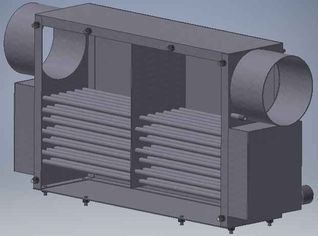
The operating parameters of the economizer (Tab. 1) were established based on certification tests performed for pellet-fired biomass boilers produced in Poland with nominal thermal outputs ranging from 12 to 100 kW. The primary function of the economizer is to recover excess heat from the flue gases and transfer it to the boiler’s heating system. Additionally, by directing the exhaust stream through the water-cooled tube bundle, the economizer promotes particulate precipitation, which helps reduce dust emissions and retain solid particles within the device.
CALCULATION METHOD
The heat flux transferred in the economizer was determined based on equation (1), taking into account the substitute heat transfer coefficient resulting from condensation and convection:

where: i – number of tubes included in the economizer [–], αz – equivalent heat transfer coefficient [W/(m2·K)], Fp – heatable surface of a single tube used to build the exchanger [m2], Δtlog – logarithmic temperature difference [K].
The logarithmic temperature difference (Δtlog) was calculated according to the classical definition for heat exchangers (2):

where: tg,in and tg,out – exhaust gas temperature at the inlet and outlet of the economizer [K], tw,in and tw,out – water temperature at the inlet and outlet of the economizer [K].
The use of Δtlog results from the fact that both the exhaust gases and the water change temperature during flow, which requires averaging this value across the entire heat exchange surface.
The heat transfer coefficients are complex due to the amount of water vapor contained in the exhaust gases supplied to the heat exchanger. The economizer is intended to function as a condensing heat exchanger, so it must be made of stainless steel, resistant to thermodynamic conditions occurring below the dew point of the exhaust gases supplied to the exchanger.
The convection coefficient was determined using a method that allows for obtaining the Nusselt number (3) during flow around a tube bundle in the configuration shown in Figure 1 and is described by the equation:

where: Prf – Prandtl number for exhaust gases in free flow [–], Prw – Prandtl number for exhaust gases in flow close to the wall [–].
To determine the Reynolds number, the outer diameter of the heat exchanger tube (dz) was assumed as the characteristic dimension. To verify the applicability of the adopted heat transfer correlations, the Reynolds numbers for both the flue gas and the water flow were estimated for the operating conditions of the economizer. Based on the measured flow rates and the characteristic tube diameter of 12 mm, the Reynolds number for the flue gas flowing across the tube bundle was within the range of approximately Regas ≈ 600–2500 (Reynolds number for flue gas), depending on the boiler load. This range corresponds to the regime typically considered in empirical correlations for crossflow over staggered tube bundles. On the water side, the total volumetric flow rate of 0.8–1.2 m3/h distributed among 42 parallel tubes resulted in Reynolds numbers in the range Rewater ≈ 700–1100 (Reynolds number for water). The internal flow therefore remained in the laminar to transitional regime. Under these conditions the hydraulic behavior of each tube is stable and consistent with the assumption of uniform flow distribution adopted in the analytical model.
This is a standard assumption for flue gas flowing around a tube bundle. The analytically determined Nusselt number for flue gas flowing around a tube bundle in the given configuration is 10.2 [–], and the heat transfer coefficient obtained from convection is 31 [W/m2·K].
The condensation of water vapor contained in the flue gas supplied to the heat exchanger intensifies the heat transfer process. This is due to the high heat transfer coefficient occurring during the phenomena accompanying phase changes. The molar fraction of water vapor in the flue gas supplied to the economizer was estimated at 13.6%. This parameter crucially defines the effect of the condensation heat transfer coefficient on heat transfer. The heat transfer coefficient during purely steam condensation is expressed by the following relationship (4):

where: ρ – condensate density [kg/m3], ρn – steam density at saturation temperature [kg/m3], λ – thermal conductivity coefficient for condensate [W/(m·K], re – heat of vaporization of condensate [J/kg], υ – kinematic viscosity coefficient of condensate [m2/s], Tn – saturation temperature [K], Ts – wall temperature [K], dz – outer diameter of the pipe [m].
The heat transfer coefficient resulting from purely water vapor condensation determined from equation (4) was 6600 W/m2·K for current conditions.
The average heat transfer coefficient αz was calculated as the weighted sum of the contributions from convection and condensation:

Where: αc – convection heat transfer coefficient (determined based on the Nusselt number), αcond – purely water vapor condensation heat transfer coefficient (according to formula (4)). The final value was determined by analytical averaging, taking into account the molar content of water vapor in the exhaust gases (13.6%).
Weighted coefficients were determined as follows:

where: αz – equivalent (overall) heat transfer coefficient [W/m2·K], αc – convective heat transfer coefficient (determined from the Nusselt number (Eq. 3) [W/(m2·K)], αcond – condensation heat transfer coefficient determined from Eq. (4) [W/(m2·K)], xH2O – molar fraction of water vapor in the flue gas [–].
The above relationship expresses the weighted average of the convection and condensation heat transfer mechanisms, in which the weighting factors correspond to the molar share of the water vapor participating in condensation and the remaining dry gas fraction. Given the experimentally determined value xH2O = 0.136, the resulting equivalent coefficient can be expressed numerically as:

which yields the final averaged value of approximately 70 W/(m2·K) for the considered economizer configuration.
The simplified analytical model described by Eqs. (6) and (7) was primarily used to estimate the overall heat transfer coefficient and to determine the required heat transfer surface of the economizer during the design stage. The validity of this approach was subsequently verified experimentally during laboratory tests of the prototype unit.
During the experiments, the thermal power recovered in the economizer was determined from the energy balance on the water side using the measured water flow rate and the temperature difference between the inlet and outlet of the device. The obtained experimental heat output values were consistent with the predicted performance range of the developed economizer variants presented in Table 2. This agreement indicates that the simplified weighted-coefficient model provides a reasonable engineering approximation of the combined convection and condensation heat transfer occurring in the investigated tube bundle under the considered operating conditions.
The average heat transfer coefficient taking into account convection and condensation was 70 W/m2·K, and the determined heat transfer surface in the theoretical economizer model was 0.95 m2. The heat transfer surface of the theoretical economizer model consisted of 42 tubes with an outer diameter of 12 mm and a length of 600 mm.
Analysing theoretical economizer model it was developed a prototype economizer for biomass-fired heating boilers, featuring a single box-shaped sheet metal housing with a single centrally located exhaust vent and consisting of a bundle of 42 screen tubes with a 1/4" diameter and a length of 600 mm. The economizer, as shown in the example, had a heat exchange surface of 0.63 m2 and a total heat transfer of 1783 W.
Experimental testing resulted in the development of a series of types (five economizers) whose geometric dimensions (increased heat exchange surface) allowed for the following operating parameters, as shown in Tab. 2.
Tab. 2
Operating parameters of the developed economizer variants
Heat exchange surface area [m2] | Heat power [W] |
0.63 | 1783 |
0.95 | 3115 |
1.68 | 4527 |
1.90 | 5499 |
2.90 | 7814 |
During the tests and operation of the economizer with the indicated technical parameters, the temperature difference of a water between the supply and return pipes of the heating boiler was maintained at a minimum level of ΔT = 25°C to achieve full condensation of moisture from the flue gases.
RESEARCH METHODS
The tests were conducted on a laboratory stand using pellet boilers with rated outputs of 25, 50, and 100 kW. Prototype economizers with various heat exchange surfaces (from 0.63 m2 to 2.90 m2) were incorporated into the system. A cross-sectional view of the boiler water block type is shown in Fig. 3. where: 1 – combustion chamber, 2 – first exhaust gas pass, 3 – exhaust gas collector (front), 4 – reversing chamber, 5 – smoke tubes, 6 – exhaust gas collector (rear), 7 – smoke conduit.
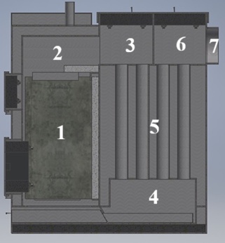
The boiler's design was based on a shell-and-tube heat exchanger system, ensuring high combustion efficiency and minimizing stack losses, and an Ecomat pellet burner. The heat exchanger and combustion chamber were made of sheet steel. The walls of the water space were reinforced with appropriate anchors to ensure the required strength of the entire water block. The front of the boiler was equipped with a door with a clean-out, a burner door, and an inspection door. The boiler had two chambers: combustion and heat exchange. The first, the exhaust chamber, located at the front of the boiler, served as the combustion and post-combustion chamber thanks to the use of ceramic catalysts, while the second, at the rear, served as a heat exchanger. Thanks to the design of the tubular reversing chambers it ensured optimal exhaust flow through the boiler, ensuring high efficiency. An ash pan was located in the lower section, accumulating ash generated during the combustion process. At the top rear of the boiler was a steel flue used to connect the boiler to the exhaust system. During the tests, this was connected directly to the economizer. The water return system (subcooled water) to the boiler passed through a preheating system in the economizer's heating section, and then the preheated water was delivered to the boiler return port. Thanks to the use of a pellet burner and a microprocessor controller, the entire device operated fully automatically.
Thermal and flow parameters on the water side were continuously monitored to characterize the operating conditions of the economizer and to assess the stability, efficiency, and dynamics of heat transfer within the system.
Thermal and flow parameters on the water side:
– Return water temperature: 50–55°C,
– Supply water temperature: 75–80°C,
– Supply-return temperature difference ΔT = 25 °C ± 2°C,
– Circulation pump capacity: 0.8–1.2 m3/h (depending on the test variant).
The following thermal parameters were measured:
– Class A Pt100 resistance temperature sensors (accuracy ±0.15 K),
– Type K thermocouple sensor for flue gas temperature measurement (accuracy ±1.5 K),
– electromagnetic rotameter for water flow measurement (accuracy ±1.5%),
– TESTO 350 flue gas analyser (accuracy ±0.2% for O2, ±10 ppm for CO),
– TESTO 380 flue gas analyser (accuracy ±10 ppm for NO, ± 5 mg/m3 for PM)
– Class 1.6 dial manometers (accuracy ±1.6%).
Measurement uncertainty:
– water temperature: ±0.2 K,
– water flow: ±2%,
– flue gas temperature: ±2 K,
– flue gas composition: ±2% of the measured value.
The economizer's thermal power was calculated based on the energy balance on the water side and, comparatively, on the flue gas side. The calculations were performed taking into account the propagation of uncertainty. The total uncertainty in determining the recovered power was within ±5%.
The woody biomass used in the tests was subject to technical analysis compliant with standards [12,13,14,15,16,17]. Tab. 3 shows the results of the technical analysis applied in the biomass tests, including the higher heating value (HHV), lowest calorific value (LHV) in [MJ/kg], and fixed carbon (FC) in [%].
Physical properties of the pellet used in the tests: diameter 5.0 mm (±0.1 mm), average length 15.0 mm (±1.0 mm) for sample lengths from 5.0 mm to 25.0 mm, and bulk density ranged from app. 728 kg/m3.
Tab. 3
Technical analysis of biomass pellet used in tests
Parameter* | Unit | Value |
Carbon, C | % | 54.74 |
Hydrogen, H | 4.97 | |
Nitrogen, N | 0.19 | |
Oxygen, O | 35.54 | |
Sulphur, S | 0.09 | |
Moisture | 5.00 | |
Ash | 0.47 | |
Volatile matter | 73.61 | |
Fixed carbon | 20.92 | |
HHV | MJ/kg | 14.93 |
LHV | 14.32 |
* Technical parameters for fuel in working condition
RESULTS
The experimental campaign focused on evaluating the thermal performance, condensate formation, and emission characteristics of the one prototype pellet boiler (nominal heat power of 21.0 kW) equipped with an integrated prototype condensing economizer (nominal heat power of 1.8 kW). A view of the complete test object, including the boiler, pellet burner, electronic controller, and view of economizer module, is provided in Fig. 4. All objects illustrate the construction of the heat recovery unit forming the monoblock configuration of the system. The combined unit was operated using certified wood pellets, and all measurements were performed under controlled laboratory conditions using standardized procedures described in PN-EN 303-5:2012 [18].
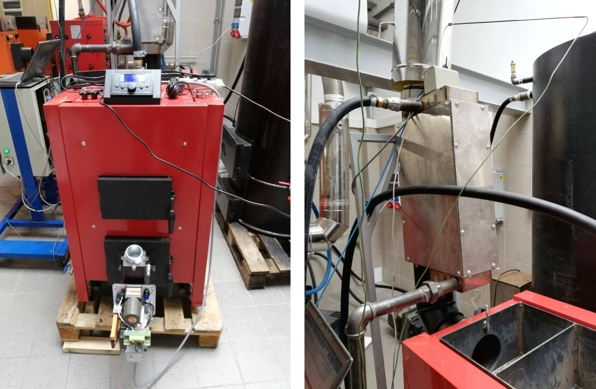
During nominal-load operation (≈ 21 kW), the system maintained stable thermal behavior, and the exhaust gas temperature was reduced to 59°C, confirming effective latent heat recovery. The integrated economizer facilitated sustained flue-gas condensation, directly increasing the usable thermal output. As a result, the gross thermal efficiency reached 107%, exceeding both the design target and the minimum requirements for high-efficiency condensing units. At reduced load, further decreases in flue-gas temperature (down to 34°C) were recorded, leading to peak efficiency values of 119% and demonstrating the robustness of the counterflow–crossflow heat exchange mechanism used in the water–gas interface of the economizer.
To verify regulatory compliance, all emission indicators required by the Ecodesign Directive (EU) 2015/1189 were recorded at both nominal and minimum load. The averaged values for particulate matter (PM), carbon monoxide (CO), and nitrogen oxides (NOx) show full conformity with the directive and correspond to the highest permissible performance class for solid-fuel heating appliances. A summary of the measured parameters relative to the Ecodesign limits will be presented in Tab. 4 (compliance with Ecodesign 2015/1189) [19]. As expected, the lowest PM emissions (≈ 14 mg/m3 at nominal load) correspond to operation under optimal flue-gas velocities and maximum utilization of the ceramic oxidation elements placed in the primary combustion chamber. Elevated CO levels at minimum load are attributed to incomplete combustion under fuel-lean conditions but remain within acceptable regulatory limits.
Tab. 4
Results obtained during testing (according to EU 2015/1189).
* reference conditions: temperature 0°C, pressure 101.3 kPa, dry exhaust gases, converted to mg/m3 for 10% O2 in exhaust gases
In addition to pollutant emissions, the boiler’s seasonal efficiency was evaluated to derive its Energy Efficiency Index (EEI) was 167.80. This parameter, together with the resulting Energy Efficiency Class was: A+++. Both indicators reflect the cumulative thermal performance under standardized seasonal load cycles and confirm that the prototype achieves efficiency levels comparable to modern low-emission pellet boilers available on the European market. Thermal stability was verified throughout the entire measurement period (approx. 5 hours per series), with the heat output remaining within ±0.5 kW of the nominal value. The monitored water-side parameters indicated uniform flow distribution across the economizer tube bundle and no signs of flow oscillation or surface boiling. Continuous flue-gas analysis confirmed that the combustion process remained stable and well-controlled, with real-time lambda regulation preventing excessive O2 fluctuations and minimizing CO spikes. These observations further validate the design approach combining a high-efficiency burner, a two-stage ceramic afterburning section, and a corrosion-resistant condensing heat exchanger.
Overall, the prototype met all predefined thermal and emission objectives. The integration of the condensing economizer enabled a substantial increase in useful heat extraction, reduced fuel consumption, and significantly lowered pollutant emissions. The achieved performance not only satisfies the requirements of PN-EN 303-5:2012 for Class 5 boilers but also demonstrates full compliance with the Ecodesign Directive (EU) 2015/1189. These findings confirm the suitability of the proposed monoblock design for further certification procedures and eventual commercialization as a high-efficiency, low-emission biomass heating appliance.
CONCLUSIONS
The research conducted in this study demonstrates that the developed condensing economizer substantially improves the thermal efficiency and environmental performance of biomass-fired heating boilers. The combination of a counterflow–crossflow heat transfer configuration and a corrosion-resistant tube bundle ensured effective recovery of both sensible and latent heat, leading to a pronounced reduction in flue-gas temperature and a considerable increase in usable thermal output. Under nominal conditions, the integrated boiler–economizer system reached a gross efficiency above 107%, while at reduced load the efficiency increased to nearly 119%. These values confirm stable condensation, enhanced heat transfer, and proper thermal integration within the monoblock system.
All measured emission indicators complied with the Ecodesign Directive (EU) 2015/1189. The low levels of particulate matter, nitrogen oxides, and carbon monoxide, combined with consistent combustion stability, confirm that the pellet burner, ceramic afterburning section, and flue-gas routing operate synergistically to maintain optimal conditions across different load stages. Based on the seasonal efficiency assessment, the system achieved an Energy Efficiency Index (EEI) of 167.8 and the highest available energy class (A+++), placing the prototype on par with leading market solutions.
Additionally, the modular construction of the economizer, with a scalable heat transfer surface ranging from 0.63 m2 to 2.90 m2, provides adaptability for boilers of various power ratings. This feature, combined with the stable thermal behavior observed during testing, indicates that the design is well-suited for future industrial implementation and commercialization in domestic and small commercial heating systems. While the obtained results are highly promising, long-term reliability under real operating conditions remains a significant aspect for further verification.
LIMITATIONS AND FUTURE WORKS
Although the study provides comprehensive insight into the operation of the proposed economizer, several limitations should be noted. First, all experiments were carried out under controlled laboratory conditions using standardized pellet fuel of consistent quality. Actual field operation may involve variable pellet properties, fluctuating moisture content, and unpredictable user behavior, all of which could influence performance. Second, the duration of each measurement cycle, while sufficient for thermal stabilization, did not include extended long-term operation necessary to fully evaluate corrosion processes, fouling rate, or ash deposition patterns on heat transfer surfaces. Third, the prototype configuration was integrated with a specific boiler model, and although the modular concept allows scaling, mechanical integration with other commercial units may require adaptation. Finally, dynamic load changes and frequent start-stop cycles were not part of the present study, which may affect both the condensation efficiency and emission signatures in real-world usage. Future research should focus on long-term operational testing under real installation conditions, including seasonal variability, user-induced fluctuations, and exposure to diverse pellet fuel qualities. Such investigations will allow a more detailed assessment of the economizer’s durability, corrosion resistance, and maintenance requirements. Additional efforts should be directed toward optimizing the geometry of the tube bundle, with particular emphasis on improving condensate drainage and minimizing fouling through enhanced flow distribution. The integration of advanced control algorithms, including model-predictive regulation and adaptive air–fuel ratio control, could further improve combustion stability and reduce transient emissions during load changes.
Computational fluid dynamics (CFD) simulations may also support the development of refined economizer geometries and help identify local heat transfer intensification zones, potentially leading to improved designs with higher energy recovery. Lastly, future work may investigate the economic assessment of the system, including lifecycle analysis, cost–benefit evaluation, and comparison with commercially available condensing solutions, to strengthen the market applicability of the proposed design.