
INTRODUCTION
The interest of researchers and engineers in studying heat transfer and fluid flow during natural, forced and mixed convection in enclosed geometries came from the crucial necessity for enhanced performance in various energy-related applications. Some of these applications include air conditioning [1], [2], drying processes [3], stenotic artery [4], geothermal reservoir utilization [5], cooling of electronics [6–8], thermal insulations [9], nuclear reactor operations [10]. There have been different studies for convection heat transfer for a variety of geometries and cavities such as square cavities, rectangular cavities, circular cavities and more [11–16].
In cooling systems, Fluid-structure interaction (FSI) has proven to be highly effective in enhancing heat transfer within cooling systems by disrupting thermal boundary layers through the use of obstacles. This approach has garnered significant interest, particularly in scenarios where fluid dynamics interact with flexible structures or membranes [17]. S.A.M. Mehryan et al [18] investigated the natural convection behavior of a square cavity containing a heated thin flexible plate which encountered a large deformation, the perpendicular side of the cavity were assumed to be cold and the horizontal walls was assumed to be adiabatic and the heated flexible thin plate was isothermal and fixed in the center of the cavity with a variation in inclination angles, the finite element method was adopted with the arbitrary lagrangian-Eulerian to solve this system. The results shown that the heat transfer and the fluid flow affected by the location of the inclination angle and the fixed point. Also, the increase in Rayleigh number with the low elasticity of the flexible thin plate gives better results than a rigid thin plate in terms of heat transfer and it was confirmed by the visualization of the Nusselt number graph. Afraz Hussain Majeed et al. [19] numerically analyzed natural convection and energy storage in Casson fluids within enclosures containing cylinders and wavy surfaces. Using a Galerkin finite element approach with an LBB-stable element, Newton’s method, and PARDISO solver, the study explored how geometry and parameters such as Rayleigh, Hartmann, Lewis numbers, and β affect flow, heat, and mass transfer. Results showed that higher Rayleigh numbers enhance concentration gradients, while increased Hartmann numbers suppress convection, offering insights into optimizing thermal storage systems. Habibis Saleh et al [20] studied numerically the contribution of two flexible fins attached on the left heated wall interact with the fluid towards the natural convection in an open square cavity, the right wall is in contact with ambient air, the rest of the walls are insulated, the movement of the end of the upper elastic fin was followed using the trigonometry function. The results showed that an increase in Rayleigh number increase the fluid velocity and made a strong fluid circulation, the identical oscillating fins permitted better fluid circulation at the left hot wall. Also, the maximum point of the heat transfer enhancements reached at the extreme amplitude tip configuration for the highest flexibility. Afraz Hussain Majeed et al. [21] numerically investigated convective thermal flow in a vertical enclosure with sinusoidal walls filled with nanofluid. This study aimed to focus on how magnetic field, oscillation and concentration particles alter heat transfer. By using the finite element method with an LBB-stable element, the study showed that lower nanoparticle volume fractions enhanced kinetic energy and Nusselt number, while higher Hartmann numbers reduced temperature and velocity highlighting optimal conditions for energy-efficient thermal management. Ahmadreza B et al [15] studied the natural convection to analyze the heat transfer rate of a circular enclosure divided in two parts, one of them is cold and the other is hot, where the fluid structure interaction is inside it, the middle wall transport the heat that goes from the hot part to the cold part, they considered the middle wall flexible. They noticed that increasing the Rayleigh number increased the flow of fluid which makes the middle wall experience a significant stress and get deformed. Therefore, these remarks let them to conclude that the dominant mechanism was the convective heat transfer, and the opposite, in low values of Rayleigh number the plate distortion and the power produced by the vortex was almost negligible. Mixed convection heat transfer in a vented cavity was investigated numerically by Md. Azizul Hakim et al [22]. This study employed a flexible flow modulator subjected to external oscillations, with air as the working fluid. The numerical simulations utilized a combination of the Galerkin finite element method and the Arbitrary Lagrangian-Eulerian (ALE) method. The focus was on evaluating the impact of various dynamic parameters, including the amplitude and period of oscillation, as well as the flexibility of the modulator, on the flow field, heat transfer performance, thermal field, thermal oscillations, and induced flow. The findings revealed that interaction with a more flexible modulator generated vortices closer to the heater wall near the modulator, whereas stiffer modulators caused the vortices to move away. Furthermore, as the modulators flexibility increased, the thermal boundary layers became thinner, leading to enhanced heat transfer. H. Saleh et al [23] studied the impact of a flexible fin on the unsteady convective flow within a square enclosure consisting of a porous layer and a vertical fluid layer, the fin connected in the left of heated wall. The Brinkman-Forchheimer-extended Darcy flow model was used in the porous layer. The computational system was solved using the finite element method and the governing equations were written by the aid of the Arbitrary Lagran-gian-Eulerian (ALE) formulation in the fluid and structure domains. The oscillation of the fin affected the area beneath the fin more significantly than the area above or in the center. Additionally, the positioning of the fin tip altered both the quantity and position of the flow circulation core which showed the impact of the position variation of the fin. Mufeng Chen et al [24] analyzed numerical and experimental methods to investigate the R-B natural convection of a TSMF with an immersed nonmagnetic particle and an external magnetic field. The results showed that an increase in Ra number increases the Nu number with low magnetic field values, in the meanwhile, the same increasing in Nu number achieved by using highest variations of external magnetic field with the lowest variations in the Ra number. Khalil Khanafer et al [25] investigated numerically phenomena of transport inside a solar porous collector where there was inside an isothermal cylinder positioning in the center of the enclosure for different parameters. The results showed that an increasing in the heat transfer caused by an increasing in the Rayleigh number and the effective thermal conductivity. Moreover, heat transfer was higher when there was a cylinder. Mohammad Ghalambaz et al [26] studied the heat transfer and fluid flow of dilatants liquids and pseudo-plastic in a square cavity that has a thin hot plate in it. The outcomes results revealed that increasing in Rayleigh number increases the buoyancy forces that lead to higher heat transfer. In addition, when they used longer flexible plate, the heat transfer reduced significantly. Bader Alshuraiaan et al [27] numerically investigated the applied effects on lid driven trapezoidal cavity by a hybrid nanofluid in addition of a flexible wall. Different Reynolds numbers along with volume fraction of the hybrid nanofluid was used in this study which showed that using a flexible wall has significantly increased the heat transfer rate. Those previous studies showed the importance of the fluid structure interaction and their effects on increasing the heat transfer.
In the present study, we focused on controlling fluid dynamics by utilizing deformable fins that bend in response to increasing Rayleigh numbers. This deformation created an opening between the top and bottom of the cavity or established a separation between these two regions, this could be useful in many industrial applications especially in thermal management field, microfluidic devices with deformable boundaries. Therefore, this investigation highlighted the effect of these combinations on the fluid flow and heat transfer performances.
MODELING APPROACH
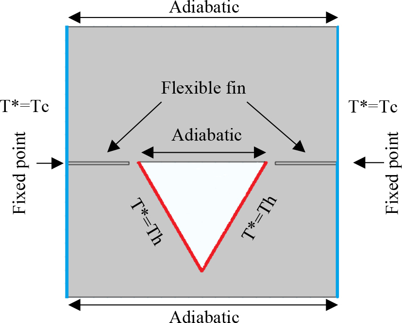
The geometry in the present study that shown in Fig. 1, is a square cavity containing a heated triangular block from the bottom and adiabatic wall from the top base of it with two flexible fins separately attached in the cold vertical walls of the cavity, the top and bottom walls of the cavity are considered to be thermally insulated. The cavity filled with an incompressible fluid. The natural convection produced a buoyancy force that make the two flexible fins to bend. The no-slip boundary condition is imposed on all the cavity walls, the triangular structure, and the two flexible fins.
Mathematical Equations
The temperature variations were assumed to be minimal. Also, the thermo physical properties and temperature was considered to be independent of each other, but not for the case of variation of the density liquid where it’s was not neglected and solved by using the Boussinesq model. Additionally, the technique of ‘’Arbitrary Lagrangian-Eulerian” (ALE) is employed besides of utilizing the assumptions mentioned earlier, the equations governing the thermal characteristics and hydrodynamics of the problem are presented below [17], [28]:
Continuity equation:
Momentum equations:
The energy equation for the fluid is defined in the Eq. (3) as:
For elastic structure domain, the energy equation for the fins can be written in Eq. (4) as:
where, u* represents the velocity vector, w* shows the moving mesh velocity vector, and P represents the pressure filed, g is the gravity vector. kf and ks signifies thermal conductivity of the fluid and the solid respectively.To define the stress tensor of Eq. (5) we applied the Neo-Hookean solid model:
The boundary conditions applicable to the external walls Eq. (8) and Eq. (9), and the two flexible fins interface Eq. (10) are defined as follow:
At the hot wall:
At the cold wall
At the interface of the flexible fin:
Also, Prandtl numbers and the Rayleigh and the Elasticity modulus are introduced as:
Prandtl number:
Elasticity modulus
To quantify the heat transfer between the two flexible fins and the fluid, the nusselt number has been used as follows in the Eq. (14) and Eq. (15):
The average Nusselt number on the wall is given by Eq. (16) as follows:
Numerical Method
In our study we employed the technique of Arbitrary Lagrangian-Eulerian (ALE) combined with finite element method (FEM) to solve the non-linear governing equations. The finite element method and the details approach are discussed in reference [29]. In our work, Gaussian quadrature, based on FEM, gives smooth solutions within the internal sub-domains. A fully coupled approach integrates the structure, heat, mesh displacements and momentum, resulting in a large matrix of coefficients, which is solved at each time step using the method of Newton.
Validation
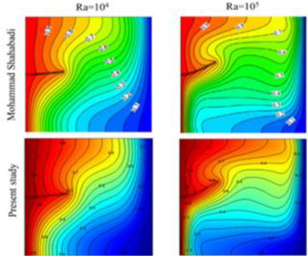
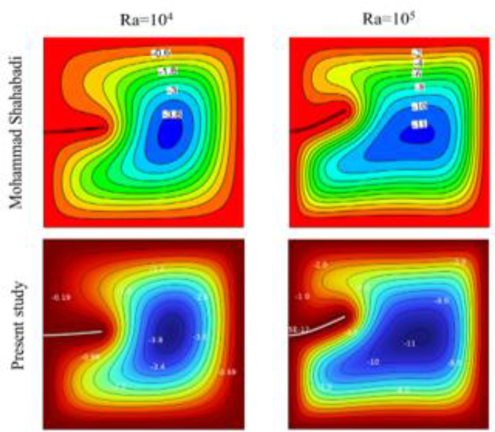
To make sure that this current study has accurate results, a validation results have been made with another study that made the same numerical technique as shown as in figure 2 and 3. [30]
Grid Study
Tab. 1.
The average Nusselt number for variety of elements number
| Number of elements | 1112 | 8139 | 12172 | 54685 | 54981 |
| Average Nusselt number | 4,3988 | 4,8061 | 4,8905 | 4,9829 | 4,9829 |
After several tests of meshing, we choose 54685 number of elements since the value of average Nusselt number didn’t change after this number.
RESULTS AND DISCUSSION
The aim of this study is to examines the effects of the fin elasticity with the variation of Ra on thermal behavior and the dynamic of the fluid in a cavity that contain a heated triangular shape. A simulation was performed to visualize the impact of the fins and the Rayleigh number as a control parameter. The range values for the Rayleigh number were (103 ≤ Ra ≤ 106) to perform moderate to strong buoyancy regimes, elasticity modulus (5×10⁹ ≤ Et ≤ 1011) to cover practical materials used in microdevices, polymers and thin fins in electronic systems, Pr=7.1. In the next following, the obtained results were presented in a qualitative way by the streamlines and the contours in figures (4–5). The temperature profiles as well as the velocity profiles for different regions via the cutlines L1, L2, L3, L4 in figures (7–14). The average Nusselt number in function of Ra in figure 15. These lines likely correspond to critical locations where temperature gradients can reveal the thermal behavior and where velocity reveal the streamlines variations across different sections of the cavity.
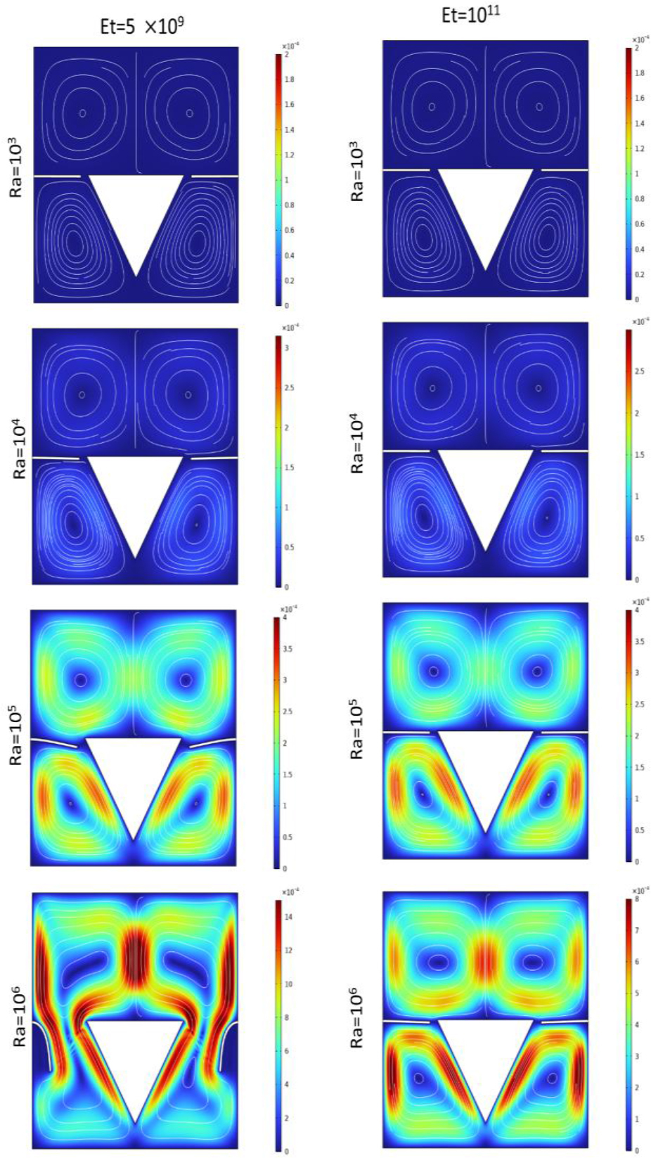
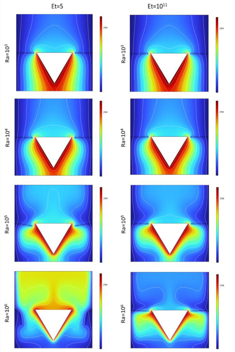
Figure 4 depict the effect of the Rayleigh number on the velocity streamlines when the elasticity modulus of the fins was equal to 5×10⁹ and 1011 respectively. For low value of Rayleigh number which is 103 there was no effect on the fins and the fluid motion was nearly negligible due to the lack of significant thermal exchange, the streamlines were separated between the top and bottom parts of the cavity for both values of the elasticity modulus. The remarkable change started when the Rayleigh number reached the value of 105 for Et = 5×10⁹, we noticed that the two fins started to bend indicating that the hydrodynamic forces started to exerts on the fins, but not for the case when the elasticity modulus was equal to 1011 where the fin acted as a fixed obstacle at this value, the fluid remained separated between the two parts of the cavity in both cases. At a Rayleigh number of 106, we observed that when the fins flexibility was 5×10⁹, the fins bended more prominently, nearly touching the cavity walls. This created a wider passage, allowing significant fluid flow and interaction between the upper and lower regions of the cavity caused by the significant effect of hydrodynamic forces on the fins at this value. In contrast, when the fins flexibility was 1011, this passage did not exist despite the high Rayleigh number, as the fins was not affected by the increased Rayleigh number, and thus, do not bend due to fixed behavior of the fins as previously mentioned.
In Figure 5 that represent the effects of the Rayleigh number (Ra) on the isotherm contours within the cavity under two distinct elasticity modulus for the fins 5×10⁹ and 1011.
For Et=5×10⁹: at low Ra values, there is minimal thermal convection within the cavity, resulting in non-uniform isotherms that indicate limited fluid motion and minimal temperature gradients. As Ra increases to 104, slight changes in the isotherms appear, indicating slight convective flow. However, the fins remain mostly unaffected due to low buoyancy forces. At Ra=105, stronger buoyancy forces cause the fins to bend slightly, significantly impacting the isotherms, fluid motion enhanced.
At the highest Ra=106, intense convection results in more distorted isotherms and efficient heat transfer between the upper and lower parts of the cavity. The fin flexibility allows the isotherms to converge near the fins, showing that heat transfer is intensified by the fluid mixing caused by fin deformation.
For Et=1011 we noticed that across all Ra values, the fins remain largely rigid due to the high elasticity modulus, resisting deformation. Consequently, the isotherm contours indicate limited fluid mixing between the upper and lower cavity regions, even as Ra increases. As Ra grows, the isotherms show increased thermal gradients, but the rigid fins restrict flow interaction, maintaining a relatively stable boundary between the upper and lower sections.
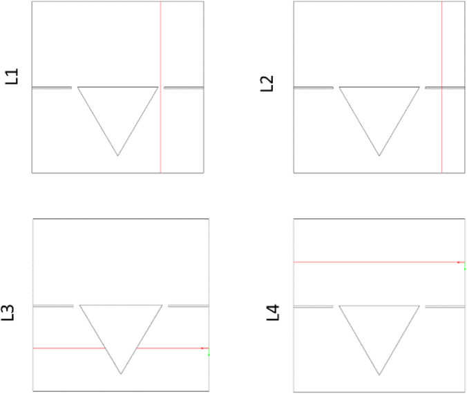
Figure 6 illustrated the cutlines (L1, L2, L3, and L4) used to measure the velocity profiles and the temperature variations within specific areas of the cavity.
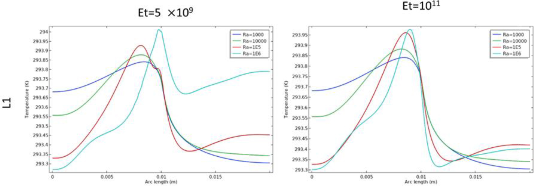
In figures 7–10, at Et=5×10⁹ the temperature profiles along the cutlines showed more pronounced variations, indicating significant heat transfer across different regions of the cavity. In figure 7, along the L1 cutline, there was minimal change when the value of the Rayleigh number was low for both elasticity modulus. At Ra=106 when Et=5×10⁹: the fin bended downward, leading to temperature increases in the region between the fin and the triangular structure (from 0.01 arc length (m) to 0.02 arc length (m)). This area exhibited higher temperatures compared to the case where Et=1011 for the same value of the Rayleigh number, which indicated the heat transfer in this area.
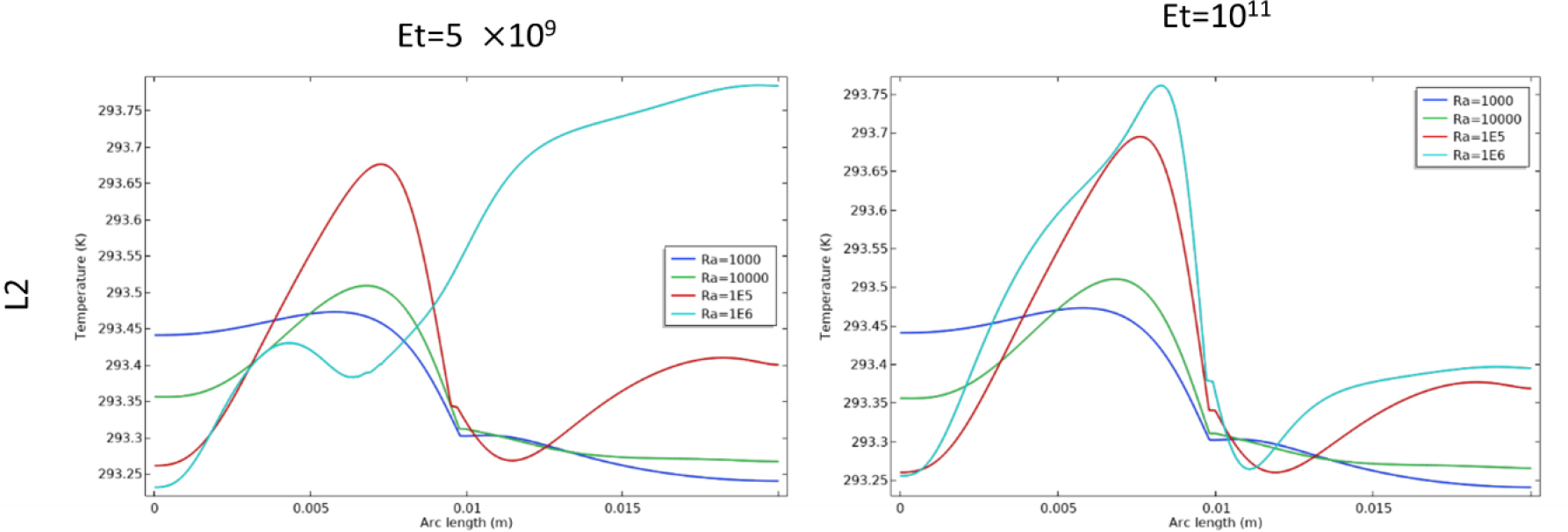
Similarly in figure 8, along the L2 cutline which intersects the fin, a comparable pattern was observed.
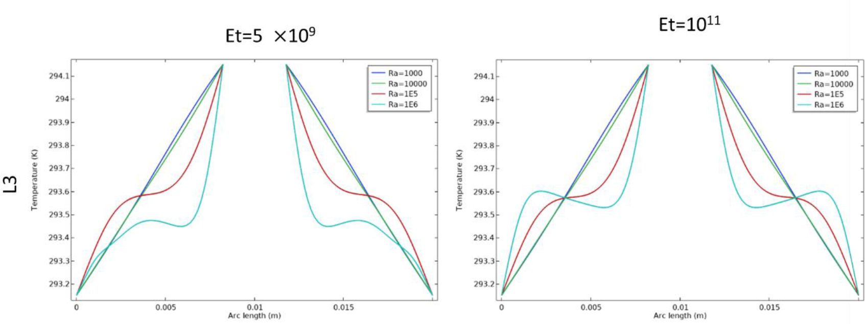
In figure 9, at the L3 cutline, variations also occurred at Ra=106, specifically, at Et=5×10⁹, the temperature near the vertical walls of the cavity was lower compared to when Et=1011, this reduction is due to the fin opening at Ra=106, allowing heat to dissipate more from this area. In contrast, when the fin remained closed, the heat remained concentrated in the lower region.
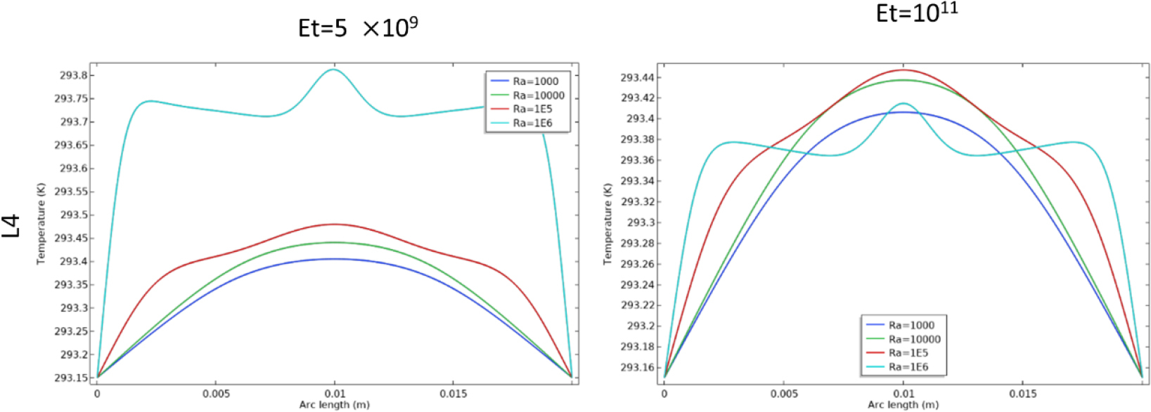
In figure 10 for the L4 cutline (upper part), an increase in temperature was observed at Ra=106 for Et=5×10⁹ which indicated that there is a heat dissipation from the lower region to the upper region. In contrast, at the same Rayleigh number but with Et=1011, the temperature was lower due to the high rigidity of the fin which made the fin to be closed, thus, restricted heat dissipation from the lower part to the upper part in this region.
These observations align with the earlier findings on fin flexibility at these elasticity values, indicating that more flexible fins improve mixing and thermal distribution, especially at higher Rayleigh numbers.
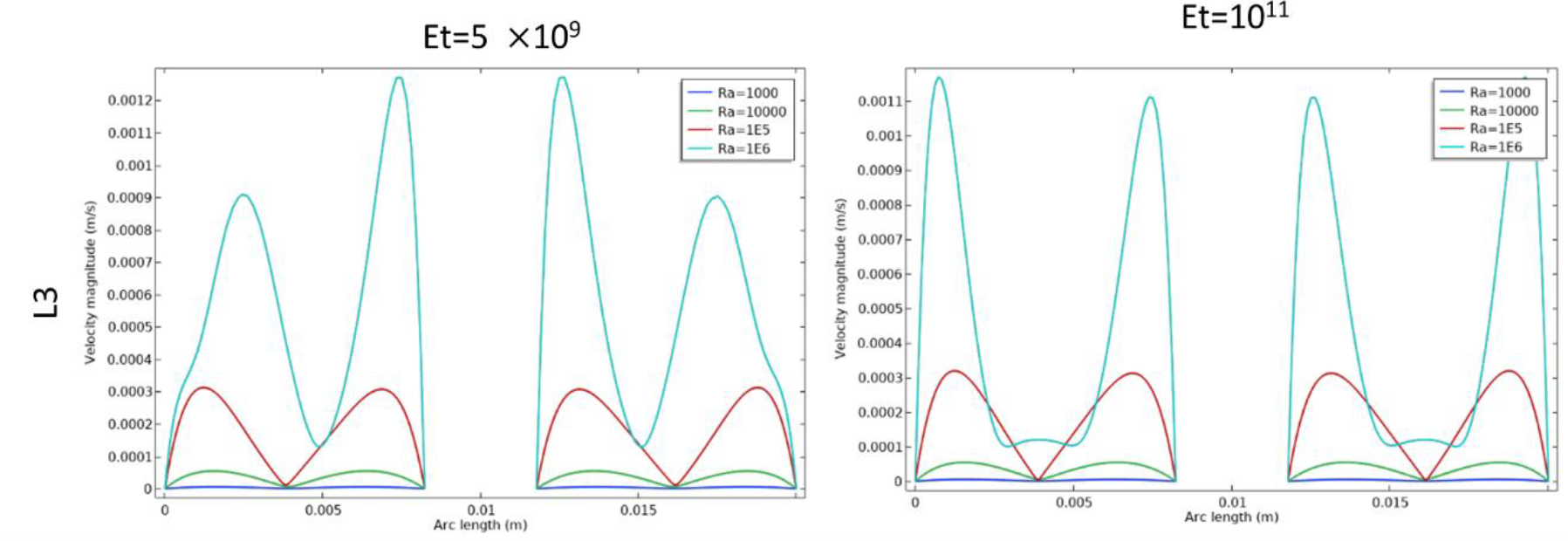
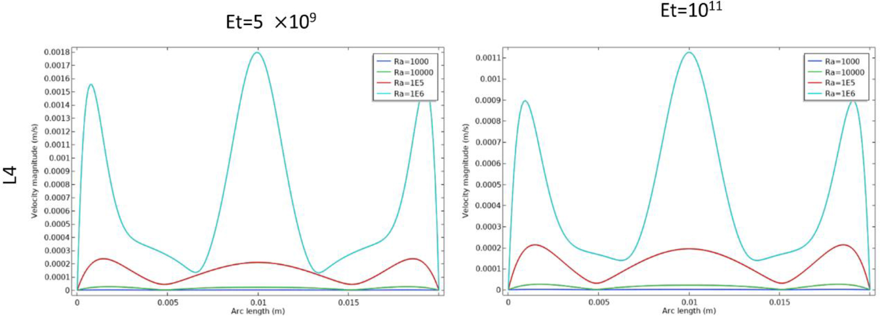
In figures 11–14 depict the velocity profiles in different areas of the enclosure according to the cutlines L1, L2, L3, L4 for different values of Ra where Et=5×10⁹, Et=1011 respectively. The velocity profiles across the cutlines L1, L2 provide a higher fluid motion within the cavity at Et=5×10⁹ compared to Et=1011 and the same observations in L3, L4 in specifics areas. As the Rayleigh number increased, the profiles show higher peak velocities, indicating stronger convective flows due to the enhanced buoyancy forces. The high rigidity of the fins limits their deformation, maintaining a more rigid structure that hinders the fluid movement between the top and bottom regions. Even at higher Rayleigh numbers, the velocities values remain subdued, showing limited convective mixing. The lower peak velocities values in these profiles confirm that the fins rigidity prevents the cavity from achieving the mixing fluid between the upper and lower parts of the cavity that seen in the flexible fin case.
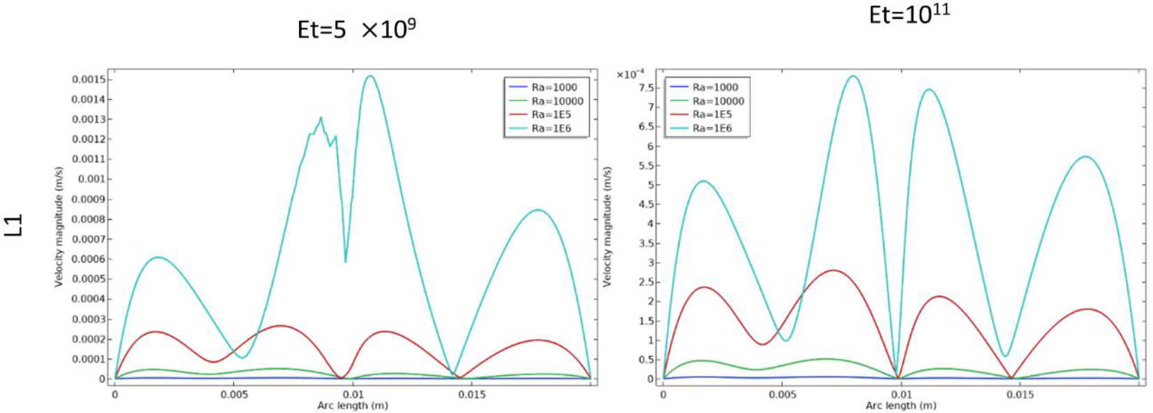
In figure 11, along L1 cutline, a significant change in the velocity speed as mentioned earlier when Et=5×10⁹. Also, at Ra=106 when Et=5×10⁹ the fin bended downward which created an opening between the upper and lower parts of the regions. Additionally, a vibrating curve appeared between (0.007 arc length (m) and 0.01 arc length (m)) in the same parameter’s values which can be attributed to the downward bending of the fin and the resulting opening, in the other hand, the curve goes smoothly between (0.01 arc length (m) and 0.013 arc length (m)) as the fin didn’t bend upward.
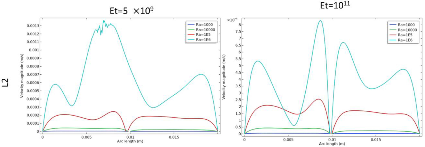
In Figure 12, similar results are observed along the L2 cutline that intersects the fin.
In figure 13, along L3 cutline where it intersects the bottom of the triangular, at (Ra=106, Et=5×10⁹), there is an increase in velocity motion near the vertical edges of the cavity compared to Et=1011 due to the opening that has been created by the bending of the fins.
In Figure 14, along L4 cutline, a slight increase is observed in middle of the cavity, while a significant increase occurs near the vertical edges.
Figure 15 represent the average Nusselt number variation as a function of the Rayleigh number (Ra) for variating values of elasticity modulus (Et) of the fins.
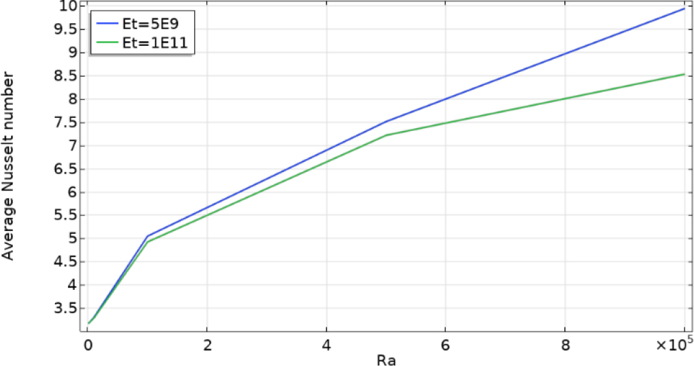
Effect of increasing Ra : As Ra increased, the average Nusselt number also increased for all elasticity values, indicating enhanced heat transfer. Higher Ra values induce greater buoyancy forces, intensifying fluid motion and thus increasing thermal exchange within the cavity.
Influence of the fin elasticity Et: for lower Et, the average Nusselt number shows a steeper increase with Ra compared to higher Et values. This suggests that flexible fins enhance convection by bending more significantly with increasing Ra, allowing fluid of the hot and cold regions to mix more effectively. Conversely, at higher Et values, the fins remain largely rigid, limiting fluid interaction between the regions of the cavity. As a result, the heat transfer enhancement due to convection is lower, even at high Ra values.
CONCLUSION
This work highlights the critical role of fin flexibility in promoting thermal interaction between the upper and lower regions of an enclosed cavity. Flexible fins facilitate fluid circulation between these areas, particularly at higher Ra values, as fin deformation opens channels that allow hot and cold fluid regions to mix. This dynamic interaction reduces thermal stratification, leading to significantly higher heat transfer rates. Conversely, rigid fins restrict the passage of fluid between the bottom and upper of the cavity, resulting in a stable thermal boundary that limits convective heat transfer. These findings underscore the importance of fin flexibility to control and create an open and a close passage of the fluid which can lead to achieve enhancement thermal mixing, which can be advantageous in designing heat transfer systems were minimizing thermal gradients and maximizing energy efficiency are priorities as well as in devices like microfluidic and biomedical devices requiring localized thermal control.
This numerical study is limited to 2d simulations with laminar flow. For this reason, future contributions has the possibilities to investigate and analyses 3D simulations, turbulent flows with different types of fluids, different flexible structural shapes.
Nomenclature
s the second Piola–Kirchhoff stress tensor
ds vector of displacement
g gravitational acceleration (m/s2);
Pr Prandtl number
T non-dimensional form of temperature
u velocity in a vector form
y cartesian coordinate in y direction
T* temperature (K)
w the vector of moving coordinate velocity
L* height and width of the cavity
x cartesian coordinate in x direction
cp specific heat capacity at constant pressure (J/kg.K);
ET non-dimensional form of the elasticity modulus
Ra Rayleigh number
Fv vector of body force
P fluid pressure
k thermal conductivity (W/(m.K));
E dimensional form of young’s modulus (N/m2)
t dimensional time
tb thickness of flexible baffle