INTRODUCTION
The date palm (Phoenix dactylifera L.) is one of the oldest cultivated fruit trees in the world, with archaeological evidence of domestication dating back over 5000 years [1-2]. It plays a vital role in food security, employment generation, and the agricultural economy of arid and semi-arid regions [3]. According to the statistics of the Food and Agriculture Organization of the United Nations, in 2023, the world's date production of dates was 9.66 million tons. The largest producers of dates were Egypt with 1.87, Saudi Arabia with 1.64, Algeria with 1.32 and Iran with 1.02 million tons. In short, 53.7 percent of production is in Asia, 45.5 percent in Africa, and the rest in Americas and Europe [4]. Beyond its economic value, the date palm also holds significant cultural and social importance in Middle Eastern and North African societies [5-6].
Despite the high importance of this crop, most date palm maintenance operations such as pollination, pruning, and harvesting are still performed manually using traditional methods [7]. These methods are time-consuming and pose considerable safety risks to workers [8-9]. Statistics indicate that manual climbing of palm trees is one of the major causes of occupational injuries and falls in date-growing regions [10]. The great height of palm trees (often exceeding 15 meters), their cylindrical and rough trunks, and challenging environmental conditions make field operations difficult and costly [1].
Under such circumstances, mechanization becomes essential to improve safety, reduce operation time, enhance productivity, and lower production costs. Developing machines capable of safely climbing palm trunks and performing necessary tasks offers an effective solution. For date harvesting, ladder-type or telescopic lifts are commonly used [11]. However, these machines are heavy, costly, and less adaptable to condensed tree spacings.
In subsequent developments, trunk-climbing devices have been investigated as lighter and more economical alternatives. At Cranfield University, Shamsi and colleagues developed a laboratory-scale electric climbing machine designed to carry out operations such as pruning, pollination, and harvesting. This machine could adjust to trunk diameter variations and smoothly traverse the protrusions left from pruning dry leaves [8]. Similarly, Rostami et al. (2013) designed an electric climbing machine equipped with a sliding chassis to adapt to trunk size changes during ascent. Other researchers proposed pneumatic or magnetic climbing systems to enhance adhesion and traction [13]. However, existing climbing machines often suffer from weak trunk adhesion, slippage, high energy consumption, and instability under load [14].
Therefore, designing an optimized climbing system with a suitable chassis and wheels, adaptive spring-loaded mechanisms for trunk diameter variation, and efficient lightweight actuators can provide an innovative and practical solution to these problems [15-16]. Despite significant progress in developing climbing machines for date palms, most existing designs still suffer from high slippage, unstable trunk adhesion, and limited adaptability to varying trunk diameters [13].
To address these limitations, this study proposes a lightweight, spring-controlled climbing mechanism featuring a hinged V-shaped chassis, concave wheels, and a spring-loaded pressure adjustment system to improve contact stability and reduce energy loss. Experimental tests and statistical analysis were conducted to evaluate the effects of wheel diameter and spring stiffness on climbing performance. The findings are expected to provide practical insights for designing efficient, safe, and region-specific climbing systems suitable for modern date palm cultivation [16].
Previous climbing robots for agricultural applications generally employ one of three mechanisms: (i) gripping or clamping systems, (ii) wheel-driven friction mechanisms, and (iii) hybrid leg-wheel configurations. Earlier systems often suffered from high mechanical complexity, slow attachment procedures, or excessive weight. Compared with these approaches, the proposed V-shaped chassis provides passive self-centering, reduced structural complexity, and improved load distribution along the trunk surface.
Recent advances in agricultural robotics emphasize the integration of electronic sensing, real-time control, and automation to improve performance, precision, and safety [9, 17]. In this context, the proposed climbing machine contributes to the field of agricultural mechatronics by combining a mechanically optimized chassis design with an electronically controlled drive system suitable for date palm applications.
Recent advancements in climbing and agricultural robots have focused on adaptive adhesion mechanisms, hybrid wheel–leg locomotion, and bio-inspired surface interaction systems (Li et al., 2025; Xiang & Honarvar Shakibaei Asli, 2025; Seo & Kang, 2024). Compared with these systems, the present study emphasizes mechanical simplicity, energy efficiency, and practical applicability for date palm agricultural conditions.
The proposed climbing mechanism represents a mechatronic approach that combines mechanical design, electronic actuation, and potential for sensor-based control to improve climbing stability and efficiency in palm tree operations.
MATERIALS AND METHODS
The proposed climbing system can be classified as a mechatronic prototype because it integrates mechanical structure, electrical actuation, and the potential for feedback-based control. The design combines a V-shaped folding chassis and concave rubber-coated wheels (mechanical subsystem) with dual independently driven DC motors (electromechanical actuation). Although the current prototype is manually operated through electrical switches, its architecture is designed to accommodate current sensors, encoders, and microcontroller-based feedback control in future developments. This integration of mechanical and electronic subsystems demonstrates the system’s readiness for semi-autonomous operation, aligning with the principles of agricultural mechatronics and robotic mechanization.
The climbing machine consists of a pair of concave metal wheels, mounted on a hinged V-shaped chassis, and pressed against the tree trunk using two identical adjustable-tension springs. Each wheel is powered by a 12 V DC electric motor equipped with a reduction gearbox, providing the required torque and rotational speed. The motors are controlled independently through electrical switches, allowing the operator to engage or disengage each wheel and maintain alignment in the horizontal plane. This configuration ensures coordinated climbing without wheel overtaking.
Initial design and force analysis on the machine and tree
A full-scale prototype of the machine was constructed and tested on a real date palm trunk. The concave wheels are covered with rubber to improve grip, and the hinged V-shaped chassis allows the machine to adapt dynamically to changes in trunk diameter, ensuring uniform contact and stable climbing. The overall design provides a clear distribution of forces during ascent and facilitates the analysis of wheel–trunk interactions.
The forces acting on the wheels and chassis during climbing were analyzed using a classical friction model [18], which relates the horizontal applied force (Fx) to the frictional resistance (Fy):

where Fy is the rolling resistance and μ is the coefficient of friction. By varying the spring tension, the wheel–trunk contact force (Fx)was tested under three different loading conditions, allowing evaluation of its impact on climbing performance, including slippage, stability, and power consumption. Force sensors mounted on the wheels enabled precise measurement of both vertical and horizontal forces transmitted to the trunk.
A free-body diagram of the climbing mechanism (Fig. 1) illustrates the vertical load (W), tangential drive force or tension produced by springs (Fx), frictional resistance (Fy), and spring tension (T) acting at the wheel–trunk interface, providing a clear visualization of mechanical interactions.
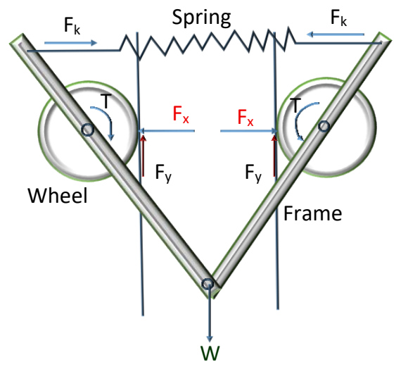
Fig. 1. Free-body diagram of the climbing mechanism showing vertical load (W), spring tension (Fx), acting on the wheel–trunk interface, frictional resistance (Fy = μFx), and motor torque (T)
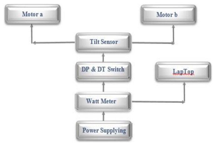
In practical field conditions, the trunk surface is not perfectly cylindrical, and bark roughness may cause asymmetric force distribution between the two wheels. This asymmetry can lead to uneven torque transmission, localized slip, and temporary imbalance. However, the hinged V-shaped chassis and independent motor control help compensate for these irregularities. The tilt sensor further stabilizes the system by temporarily stopping the faster wheel to restore alignment.
Tree trunk diameter directly affects the contact angle between the wheels and trunk surface. For smaller diameters, the contact arc increases, potentially improving grip but increasing rolling resistance. For larger diameters, contact becomes more localized, requiring higher spring force to maintain sufficient normal pressure. Therefore, optimal spring tension may vary depending on trunk diameter. The schematic view of the tree climbing robot, including (a) the front view and (b) the back view, is shown in Fig. 2.
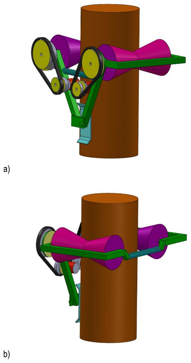
Table 1 summarizes the main technical specifications of the proposed robot, including its key design and performance parameters for clarity and ease of reference.
Robot self control of climbing
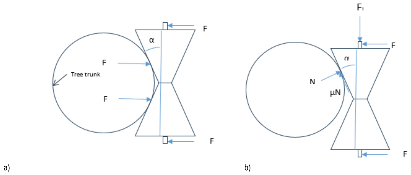
If a lateral force Fl, as shown in Fig. 3, tends to pull the conical rollers toward one side of the trunk (Fig.3b), the conical roller geometry is designed such that the rollers automatically slide back to the stable position shown in Fig.3a. The following analysis describes the design principle and stability conditions of the self-centering mechanism.
Writing the equilibrium equations in the top view for position (b) in Fig. 3 yields. The relationship between the forces acting on the conical roller system can be expressed in matrix form as:
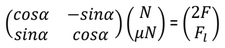
which yields:


The rollers of the robot will automatically return from the unstable position (b) in Fig. 3 to the stable self-centering position (a) if the following condition is satisfied:

Rearranging Eq. (1) to express N and substituting into Eq. (3) gives:

Solving Eq. (4) for the spring force F yields the minimum required spring tension:

Dividing numerator and denominator by cosα results in:

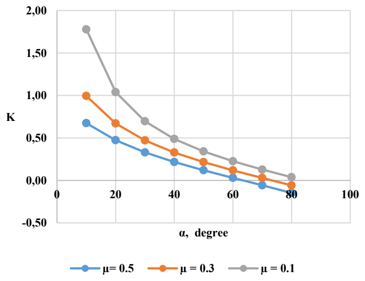
Let K be defined as:

Thus, Eq. (6) can be rewritten as:

Equation (6) defines the minimum required spring force F, which depends on the lateral disturbance force Fl, the coefficient of friction μ, and the cone angle α.
Furthermore, the stability condition imposes a constraint on the cone angle. The denominator of Eq. (6) must remain positive, leading to:
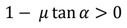
and therefore:
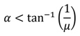
For μ=0.5, the maximum allowable cone angle is:
α < 63.4°
Finally, Eq. (8) provides the minimum spring force required to ensure self-centering behavior. Under this condition, the robot maintains stable climbing performance without lateral deviation and automatically returns to the stable configuration shown in Fig.3a.
The relationship between the parameter K, the cone angle α, and the friction coefficient μ is illustrated in Fig. 4. As shown in this figure, the value of K decreases as the cone angle increases, which directly affects the minimum spring force required for self-centering.
Climbing performance evaluation
The climbing performance of the proposed device was assessed under three different loading conditions: no load, 120 N, and 220 N. Each experiment was repeated three times to ensure the consistency and reliability of the results. Climbing speed was measured using a digital encoder mounted on the wheels, while the slip ratio was calculated as follows [19-20]:

where L represents the theoretical path length based on wheel rotations, and L1is the actual distance traveled by the device on the tree. The theoretical path length L was determined using:

where m denotes the wheel circumference and n is the number of wheel rotations required to cover the climbing distance L1. This method provides a quantitative measure of slippage during operation, allowing comparison across different loading conditions.
Estimation of mechanical power, electrical power, and efficiency
The mechanical power required for climbing was estimated by considering the total forces acting on the device and its climbing speed [21]:

where Pmech is the total mechanical power (W), W₁ is the weight of the device (N), W₂ is the rolling resistance force (N), W₃ is the additional load (N), and V is the climbing speed (m/s).
The electrical power consumption was calculated using the measured current multiplied by the supply voltage (12 V).
In this study, the efficiency (ηsystem) is defined as the ratio of useful mechanical output power required to lift the robot against gravity to the total electrical input power supplied to the system [14]:

where m is the total mass, g is gravitational acceleration, v is climbing speed (m/s), and Pin is the measured electrical input power.
It should be noted that motor efficiency (ηmotor), defined as shaft mechanical power divided by electrical power at the motor terminals, was not separately measured in this work.
Experimental setup and computational methods
A pilot experiment was conducted on a single date palm trunk to verify the feasibility of the proposed climbing mechanism. Based on the theoretical calculations and design parameters established in this study, a laboratory-scale prototype was constructed, as shown in Fig. 5. Future work will involve testing across multiple trees with varying trunk diameters to assess performance consistency under realistic field conditions.
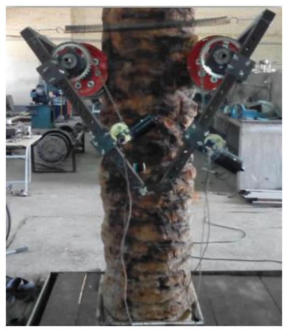
For this study, a palm trunk with a height of 2.5 m and a diameter of 0.40 m was used at the Biosystems Mechanical Engineering Laboratory of Shahid Bahonar University. The chassis was designed with short arms and a spring-based attachment system, allowing the device to be easily mounted or detached by a single operator without specialized tools. This design aimed to reduce setup time compared to previous prototypes, facilitating faster execution of orchard operations such as harvesting, pruning, pollination, and spraying.
The selected tree, with a relatively rough trunk surface, provided a challenging yet controlled condition for evaluating the climbing mechanism. Following protocols from previous agricultural robotics studies, the coefficient of friction between the rubber wheels and the trunk surface was empirically assumed to be 0.5 (Rostami et al, 2013).
The experimental design was implemented using SAS software (version 9) and a completely randomized factorial design. Three independent variables were considered: loading levels (factor A) (0 N, 120 N, and 220 N), wheel–trunk contact force (factor B) (425 N, 584 N, and 743 N), and wheel diameter (factor C) (0.16 m and 0.19 m). Each combination of variables was tested three times, and the effects on climbing speed, slip ratio, and system efficiency were recorded and analyzed.
This setup provided a systematic approach to evaluate the performance of the climbing device under controlled laboratory conditions and generated quantitative data for optimizing design parameters in future studies.
Control and power system
During laboratory experiments, the system was powered through an external DC supply connected via a flexible cable to ensure accurate power measurement. The cable was positioned vertically and manually monitored to prevent entanglement. Future prototypes will integrate an onboard lithium battery system to enable fully autonomous climbing.
The DPDT switch controls the robot’s climbing and descent operations. The tilt sensor detects any deviation in the horizontal alignment of the wheels to maintain the robot’s stability. When a deviation is detected, the sensor sends a corrective signal that stops the motor on the side causing the imbalance, allowing the opposite wheel to rotate and restore the robot to its horizontal orientation. Once the alignment is corrected, the tilt sensor reactivates the stopped motor. This control cycle repeats continuously during both the ascending and descending phases of the climbing operation. The watt meter measures the electrical power consumption of the system during operation, and the collected data are recorded on a laptop computer for further analysis (Fig. 6).
RESULTS AND DISCUSSION
The climbing machine consists of a pair of concave rubber wheels, each driven by a 12 V, 50 W electric motor controlled by separate electrical switches. The motor speed is reduced through a worm gearbox and then transmitted to the wheels via a chain and sprocket system.
In this experiment, loading, horizontal wheel–trunk contact force, and wheel diameter were examined as factors influencing the climbing speed of the V-shaped chassis machine. The analysis of variance (ANOVA) indicated that the effects of each factor, both independently (main effects) and in combination (two-way and three-way interactions), on climbing speed, wheel slip, and system efficiency were significant at the 1% level. The results of the ANOVA for the independent variables on the measured responses are presented in Table 2.
Tab. 2. Analysis of variance for factors affecting the response variables
Based on the results of the analysis of variance, the main effects of each independent factor—including loading force, horizontal wheel contact force, and wheel diameter—on the dependent variables (climbing speed, slip, and efficiency) were significant at the 1% probability level. In addition, significant two-way and three-way interaction effects were observed. This indicates that the effect of each independent factor alone depends on the levels of the other factors, and its influence cannot be interpreted in isolation.
To further explore the relationships among factors, three-way mean comparisons were conducted. These comparisons enabled a simultaneous assessment of all factors, illustrating how their interactions influence system performance. Due to space limitations, only the most critical three-way comparisons are presented in Fig.s, while two-way and main effects are discussed in the text.
Climbing speed
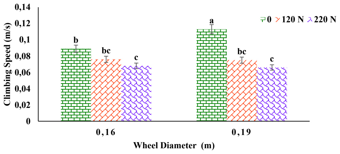
The two-way interaction between horizontal wheel contact force and loading on the climbing speed of the device was significant (Fig. 7). Increasing the horizontal wheel force amplified the negative effect of loading on speed, such that at higher levels of contact force, a greater reduction in climbing speed was observed. This behavior can be attributed to the increase in total resistance forces, including rolling and frictional resistance, which reduces the net mechanical power available for vertical motion [22-23]. Conversely, under certain conditions, improved wheel–trunk contact allowed the device to maintain or slightly increase climbing speed, indicating a dynamic equilibrium dependent on specific loading levels and trunk surface irregularities.
It should be noted that the analytical force model presented in Fig. 1 assumes symmetric force distribution between the two wheels. However, during experimental tests, minor speed fluctuations were observed when the robot encountered local bark protrusions or irregular trunk geometry. These surface irregularities generated temporary asymmetric normal forces, resulting in short-term torque imbalance between the wheels. The hinged chassis mechanism and tilt-sensor-based corrective control effectively compensated for these asymmetries by reducing rotational speed on the dominant side until horizontal alignment was restored. The observed speed variation under identical test conditions remained below 5%, indicating acceptable stability despite non-ideal real-world conditions.
The measured standard deviation of climbing speed across repetitions was less than 5%, indicating relatively smooth and repeatable motion. Minor fluctuations were observed when the wheels encountered bark protrusions, but the control system effectively restored alignment within seconds.
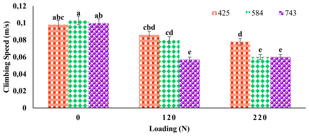
The interaction between loading and wheel diameter is shown in Fig. 8. Under no-load conditions, increasing wheel diameter significantly enhanced climbing speed due to the larger wheel–trunk contact area and improved force transmission.
However, at higher loading levels, this advantage was reduced or neutralized. This phenomenon suggests that the positive effect of larger wheels at low loads is counteracted by the increased overall resistance under heavier loads [8, 12].
The combined effect of horizontal wheel contact force and wheel diameter was also evaluated (Table 3). Although climbing speed varied across different combinations of these two factors, the differences were not statistically significant at the 5% probability level, indicating that neither factor alone significantly influenced performance. This finding aligns with previous studies showing that wheel contact and diameter effects are context-dependent and often interact with other variables such as load and surface conditions.
Tab. 3. Comparison of mean interaction effects of horizontal wheel contact force and wheel diameter on climbing speed (m/s)
| Wheel Diameter (m) | Horizontal Wheel Contact Force (N) | ||
|---|---|---|---|
| 743 N | 584 N | 425 N | |
| 0.16 | 0.072 | 0.074 | 0.086 |
| 0.19 | 0.073 | 0.092 | 0.089 |
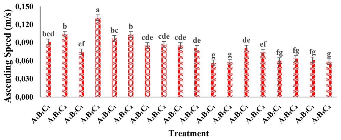
Finally, the three-way interaction among loading (A), horizontal wheel contact force (B), and wheel diameter (C) was analyzed (Fig. 9). Statistical analysis using Duncan’s multiple range test at the 5% probability level revealed a significant interaction effect on climbing speed. The highest climbing speed (0.131 m/s) was observed under A₁B₂C₂ conditions (0 N load, 584 N horizontal wheel force, and 0.19 m wheel diameter), suggesting this as the optimal setting under no-load conditions. At 120 N loading, treatment A₂B₁C₂ (425 N horizontal wheel force, 0.19 m diameter) achieved the best performance at 0.087 m/s. For 220 N loading, treatment A₃B₁C₁ (425 N horizontal wheel force, 0.16 m diameter) resulted in 0.081 m/s. No statistically significant differences were observed among combinations at the two higher loading levels. These results indicate that careful selection of wheel diameter, horizontal contact force, and loading conditions can considerably enhance climbing efficiency, which is critical for agricultural operations such as harvesting, pruning, and pollination [2].
These results indicate that selecting the most suitable combination of the three parameters, depending on the load conditions, can considerably enhance the efficiency of the device, particularly for agricultural operations such as harvesting, pruning, and pollination.
Wheel slip analysis
Under practical climbing conditions, asymmetric wheel-trunk contact may lead to uneven slip distribution between the two wheels. Although slip ratio was calculated based on total displacement, localized asymmetric slip was visually observed when one wheel encountered rough bark segments. This effect was more pronounced under higher loads and lower spring forces. Increasing spring tension improved contact uniformity and reduced asymmetric slip tendencies.
The analysis of variance (ANOVA) for factors affecting wheel slip-including loading (A), horizontal wheel contact force (B), and wheel diameter (C)-indicated that all main effects and interaction terms were significant at the 1% probability level, except for the A×C interaction (loading×wheel diameter), which was not significant (Table 1).
Two-way Interaction: Wheel Contact Force×Loading
The interaction between wheel contact force and loading on wheel slip is illustrated in Fig. 10. At the highest wheel contact force (743 N), slip percentages were approximately 10% (no load), 15% (120 N load), and 19% (220 N load), with no statistically significant differences among these levels. However, at lower wheel force levels (584 N and 425 N), increasing the load significantly increased slip. For example, at 425 N, slip rose from about 12% (no load) to 27% (220 N load).
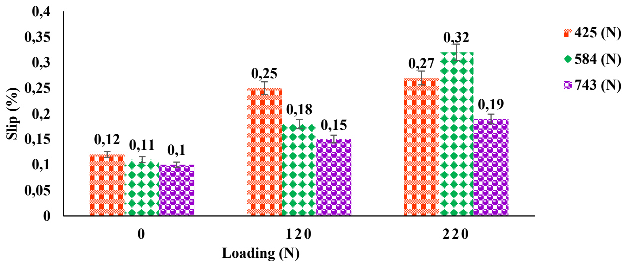
These results suggest that higher wheel contact forces reduce slip, while increasing load at a given wheel force level increases slip. Maintaining a balance between wheel force and load is therefore crucial for minimizing wheel slip [22-23].
Two-way Interaction: Wheel Contact Force × Wheel Diameter
Fig. 11 presents the interaction between wheel contact force and wheel diameter on slip. At the highest wheel force (743 N), slip was approximately 6% for 0.16 m wheels and 24% for 0.19 m wheels, demonstrating a significant difference. At the lowest wheel force (425 N), slip increased from 15% for 0.16 m wheels to 27% for 0.19 m wheels.
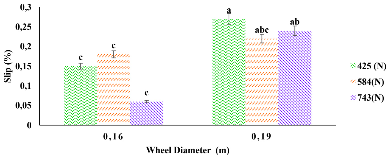
These results indicate that larger wheels reduce contact pressure per unit area, which may increase slip due to reduced tire grip, whereas higher wheel contact force enhances adhesion and friction, decreasing slip [8, 12]. The minimum slip occurred with the combination of 0.16 m wheels and 743 N force, whereas the maximum slip was observed with 0.19 m wheels and 425 N force.
Three-way Interaction: Loading × Wheel Contact Force×Wheel Diameter.
The combined effect of loading (A), horizontal wheel contact force (B), and wheel diameter (C) on wheel slip was analyzed using Duncan’s multiple range test at a 5% confidence level (Fig. 12). The results highlighted significant differences among certain combinations:
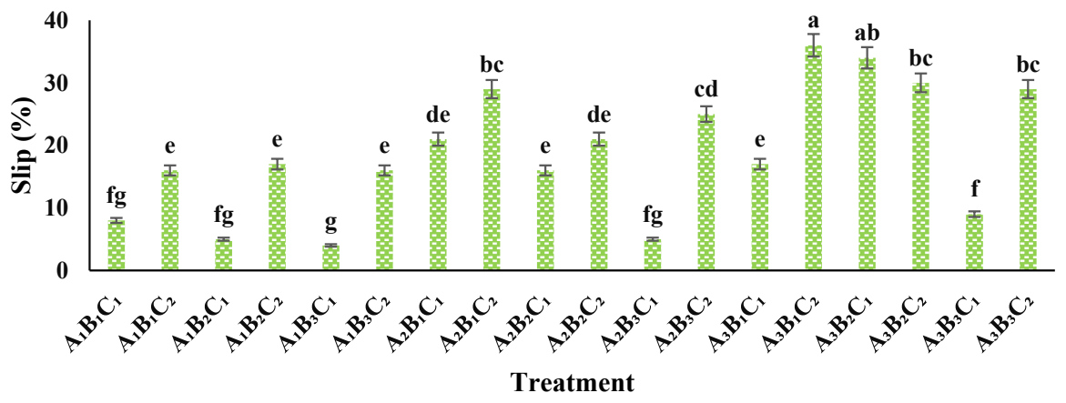
Fig. 12. Three-way interaction effect of loading (A), horizontal wheel contact force (B), and wheel diameter (C) on wheel slip
At 120 N loading, the optimal combination was A₂B₃C₁ (120 N load, 743 N horizontal wheel force, 0.16 m wheel diameter) with a slip of 3.5%. At 220 N loading, the optimal combination was A₃B₁C₁ (220 N load, 425 N horizontal wheel force, 0.16 m wheel diameter) with a slip of 17.3%.
These findings indicate that selecting appropriate combinations of wheel diameter, contact force, and loading can significantly reduce slip, improving the device’s performance and operational efficiency for tasks such as harvesting, pruning, and pollination.
System efficiency
The analysis of variance (ANOVA) for factors affecting device efficiency indicated that all main effects, two-way, and three-way interactions were significant at the 1% confidence level (Table 2).
Two-way Interaction: Wheel Contact Force×Loading.
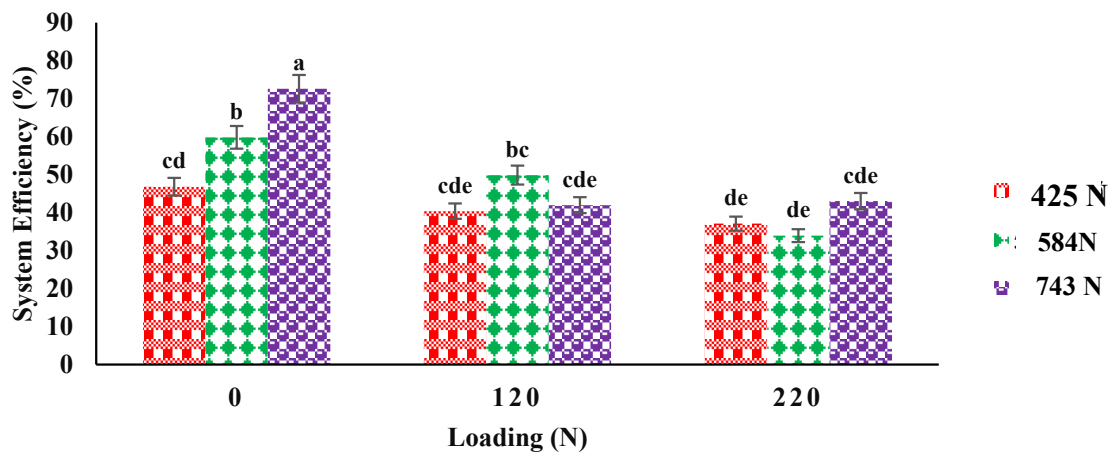
The interaction between wheel contact force and loading on efficiency is shown in Fig. 13. The highest efficiency (~72.60%) was observed under no-load conditions with the maximum wheel contact force (743 N), likely due to improved grip and traction [22-23]. Conversely, the lowest efficiency (~37.09%) occurred at 220 N loading with 425 N wheel contact force. These results suggest that increasing wheel contact force has the most positive effect under low loading, while heavy loading with low wheel force substantially reduces efficiency.
Two-way Interaction: Loading×Wheel Diameter.
The interaction between loading and wheel diameter is illustrated in Table 4. At no-load conditions, 0.19 m wheels achieved significantly higher efficiency (67.76%) compared to 0.16 m wheels (37.69%), indicating a positive effect of larger wheels on efficiency under minimal loading. At 120 N and 220 N loading, no significant differences were observed between wheel diameters, suggesting that increased vertical load diminishes the advantage of larger wheels [8, 12]. In general, efficiency decreased as loading increased, regardless of wheel diameter.
Tab. 4. Comparison of mean interaction effects of loading and wheel diameter on system efficiency.
| Wheel Diameter (m) | 220 N | 120 N | No Load |
|---|---|---|---|
| 0.16 | 37.69(b) | 44.85(bc) | 52.61(b) |
| 0.19 | 38.36(c) | 43.39(bc) | 67.76(a) |
Means with different letters in each column, according to Duncan’s multiple range test at a 5% probability level, indicate significant differences.
Two-way Interaction: Wheel Contact Force×Wheel Diameter
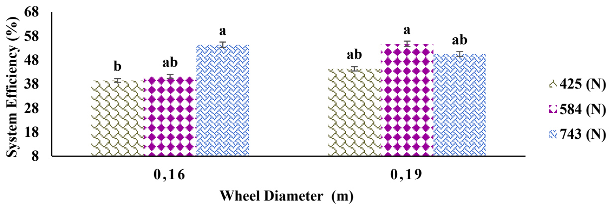
Fig. 14 illustrates the interaction between wheel contact force and wheel diameter. In general, increasing both parameters improves efficiency, except at the highest wheel force (743 N), where excessive adhesion and rolling resistance slightly reduce efficiency. These results highlight the importance of balancing wheel force and diameter to optimize traction and device performance.
Three-way Interaction: Loading × Wheel Contact Force × Wheel Diameter
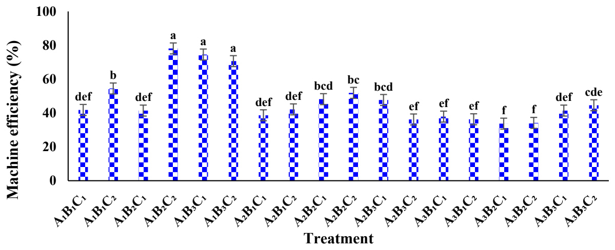
The combined effect of loading, wheel contact force, and wheel diameter on efficiency is presented in Fig. 15. The results indicate that different combinations yield statistically significant and non-significant differences.
Under no-load conditions (0 N), combinations A₁B₂C₂ (584 N, 0.19 m), A₁B₃C₁ (743 N, 0.16 m), and A₁B₃C₂ (743 N, 0.19 m) produced similar efficiencies with no significant differences. At medium load (120 N), the combination A₂B₂C₂ (584 N, 0.19 m) achieved the highest efficiency (51.9 %), significantly higher than A₂B₁C₂ (42.1%). Under high load (220 N), the combination A₃B₃C₂ (743 N, 0.19 m) was optimal due to higher load-carrying capacity and acceptable efficiency (44.6 %). While A₃B₁C₁ (425 N, 0.16 m) showed slightly lower slip and efficiency (37.9 %). Considering load capacity, A₃B₃C₂ is preferred despite higher slip (29%).
These results demonstrate that selecting appropriate combinations of wheel diameter, contact force, and loading can enhance efficiency and maintain effective performance under various load conditions, which is critical for agricultural operations such as harvesting, pruning, and pollination [17,24].
Machine attachment time to the tree
The time required to attach the climbing machine to the date palm trunk was evaluated over 10 repetitions. The recorded times ranged from 19 s to 22.1 s, with a mean attachment time of 20.94 s. Using the 95% confidence interval, calculated as:

The attachment time was determined to lie between 20.2 s and 21.7 s with 95% confidence.
Compared to previous designs, such as the sliding-chassis climbing machine reported by Rostami et al. (2013), which had an average attachment time of approximately one minute, the current hinged V-shaped chassis design demonstrates a significant reduction in attachment time. This improvement facilitates faster execution of orchard operations, including harvesting, pruning, pollination, and spraying, thereby enhancing overall operational efficiency.
Load-carrying ratio
The load-carrying ratio is a crucial indicator for evaluating and comparing the performance of climbing machines. This ratio expresses the machine’s capacity to carry a load relative to its own weight, with a higher value indicating greater load-carrying capability. The load-carrying ratio (LCR) is defined as:

For comparison, the sliding-chassis machine reported by Rostami et al. (2013) had a maximum load capacity of 200 N and a total weight of 15.35 kg, resulting in an LCR of 1.3. In contrast, the wheel-based climbing machine developed by Shamsi (1998), weighing 137 kg with a load capacity of 100 kg, achieved an LCR of 0.76 [8].
For the V-shaped hinged chassis machine presented in this study, with a weight of 22 kg and a load capacity of 220 N, the load-carrying ratio was estimated at 1.0. This value indicates that the current design offers a balanced combination of lightweight structure and adequate load-carrying capacity, outperforming heavier machines like Shamsi’s in terms of relative efficiency, while maintaining comparable functionality to the sliding-chassis design [8].
Machine performance
Based on the Duncan multiple range test for the three-way interaction among loading (A), wheel contact force (B), and wheel diameter (C), three configurations—A₃B₁C₁, A₃B₃C₁, and A₃B₃C₂—were identified as most suitable for high load-carrying operations. Each configuration excels in specific performance metrics: A₃B₁C₁ achieved the highest climbing speed (0.118 m/s), A₃B₃C₁ exhibited the lowest wheel slip (9.3%), A₃B₃C₂ reached the highest efficiency (44.6 %).
Considering a balanced combination of speed, slip, and efficiency, A₃B₁C₁ is identified as the optimal configuration, providing high climbing speed with acceptable slip (17%) and satisfactory efficiency (37.9%).
Under no-load conditions, the current V-shaped hinged chassis machine achieved a climbing speed of 0.131 m/s and efficiency of 20.8%, demonstrating superior performance compared to the sliding-chassis machine reported by Rostami et al. (2013), which achieved a speed of 0.10 m/s and efficiency of 25%. The best performance of the sliding-chassis machine occurred at a spring-induced contact force of 145 N, with a climbing speed of 0.088 m/s, wheel slip of 12.56%, and efficiency of 32.14%.
Overall, increasing the spring force from 425 N to 743 N reduced slippage by approximately 12% and improved climbing speed by 18%. The optimal configuration, combining a spring force of 584 N with a 0.19 m wheel diameter, provided the best balance of speed (0.131 m/s), slip (10.1%), and efficiency (20.8%). These findings underscore the critical role of contact pressure and wheel size in enhancing the climbing performance of date palm machines [8, 12].
The integration of current sensors and encoders in future prototypes will enable real-time monitoring of climbing performance, supporting data-driven optimization and predictive maintenance.
Compared with earlier designs such as the sliding-chassis system (Rostami et al., 2013) and heavy wheel-based harvesters (Shamsi, 1998), the present robot demonstrates: 65% reduction in attachment time, Improved load-to-weight ratio, Lower mechanical complexity, and Reduced slip under optimal spring force.
The proposed V-shaped chassis provides several practical advantages for field applications. First, the robot can be quickly attached to the trunk without complex locking mechanisms. Second, the mechanical structure is relatively simple, reducing manufacturing cost and maintenance requirements. Third, the lightweight configuration improves portability and reduces required motor power. Finally, the hinged V-geometry combined with spring loading enables automatic passive adaptation to trunk diameter variations, maintaining sufficient contact pressure without active adjustment.
These improvements position the proposed system as a more practical and lightweight alternative for modern date palm orchards.
CONCLUSIONS
This study quantitatively demonstrated how mechanical parameters—particularly spring contact force and wheel diameter—affect the climbing speed, slip ratio, and energy efficiency of a palm-tree climbing mechanism. Statistical analysis confirmed that increasing spring force from 425 to 743 N reduced average slip by approximately 12% and improved stability. Larger wheel diameters expanded the contact area with the trunk and further minimized slip, but beyond 0.19 m, the added mass slightly decreased climbing speed. The optimal configuration—584 N spring force and 0.19 m wheel diameter—yielded a climbing speed of 0.131 m/s, slip of 10%, and efficiency of 70.7%. Load tests up to 10 kg confirmed sufficient mechanical stability and load-carrying capacity, while the hinged V-shaped chassis reduced attachment time from 60 s to 20.9 s, improving ergonomics and setup efficiency. Under the heaviest load (220 N), the configuration maintained stable climbing motion with 0.118 m/s speed and 17% slip. Overall, optimization of spring force and wheel diameter significantly enhanced climbing stability and energy efficiency. The optimal operating condition was achieved at a spring force of 500 N under moderate loading (200 N), resulting in minimal slip (<3%), a stable climbing speed of approximately 0.042 m/s, and improved overall system efficiency. This configuration provided reliable vertical stability without detachment or excessive oscillation, making it suitable for practical date palm maintenance tasks such as pruning, pollination, and inspection. Since this research was based on a single-tree pilot experiment, future studies should extend testing to multiple trees with varying trunk diameters and surface textures to validate scalability and long-term reliability.
The system can be classified as a mechatronic prototype since it integrates mechanical design and electronic control elements, with the potential for future implementation of automatic sensing and feedback mechanisms.
The study demonstrates the potential of integrating mechatronic control and sensor feedback systems into palm-climbing devices, paving the way toward semi-autonomous agricultural robots for tree maintenance.
Limitations of the present study include testing on a single tree, cable-based power supply, and absence of full autonomous control. Future improvements will focus on battery integration, adaptive spring-force control using feedback sensors, multi-tree field validation, and weather-resistant structural optimization.
Compared to conventional clamping-based climbing mechanisms, the proposed V-shaped configuration enables faster installation, lower mechanical complexity, lighter structural design, and automatic geometric adaptation to varying trunk diameters, thereby improving practicality for date palm maintenance operations.
The proposed robot functions as a modular vertical mobility platform that can be adapted for various date palm maintenance operations. By scaling the structural frame and reinforcing load capacity, the system can either support a human operator or integrate a lightweight robotic manipulator. Interchangeable end-effectors such as pruning cutters, pollination tools, vibration-based fruit shakers, or spraying units can be mounted depending on the intended task. Therefore, the platform provides a flexible foundation for mechanized cultural operations in tall palm orchards.
In a manned configuration, the platform does not require additional degrees of freedom, as maintenance tasks would be performed manually by the operator. In contrast, for a fully autonomous system, integration of a robotic manipulator is necessary. A minimum of four degrees of freedom would be required to provide vertical positioning, radial reach, angular adjustment, and tool actuation. Additional modules such as a vision sensor, control unit, and interchangeable end-effectors would be required for practical field implementation.