INTRODUCTION
The subject of the analysis are sandwich panels, which consist of two stiff but thin facings and a thick but shear-deformable core. These types of panels are used in many industries including aviation, space, automotive, and construction. Metal facings constitute protective layers against external factors, and from a mechanical point of view, their role is to take over the bending of the panel caused by external loads. The core typically serves as a thermal insulation layer. Therefore, it is made of lightweight materials with low stiffness modules, which also means high susceptibility to deformation. For construction applications, the core of sandwich panels is made of materials such as polyisocyanurate foam (PIR), expanded polystyrene (EPS), and mineral wool.
One of the basic and most common mechanisms of sandwich panels failure is the local loss of stability of the facing, which is subjected to compressive stresses. Facing deformations are limited by the core, but at a certain level of facing compression, the form of facing deformation suddenly changes due to buckling. The characteristic form of this deformation (periodic waving) is called wrinkling, and the critical compressive stress in the facing is called the wrinkling stress. The stress is calculated as the critical force divided by the facing area.
The problem of determining the wrinkling stress has been discussed many times in the literature. In the vast majority of cases, it was reduced to the issue of a thin facing resting on an infinite elastic substrate. This assumption seems to be correct because it has been repeatedly proven that the deformation of the facing is influenced only by a small area of the core adjacent to it (of the order of a few centimeters, see [1, 2, 3]).
Classical solutions to the problem of determining the wrinkling stress were presented by Hoff and Mautner [4], and Plantema [5], who used an energy approach. In [4], a linear deformation decay function was used, whereas in [5], an exponential decay function was implemented. Another method, namely the differential equation method was applied by Allen [6]. Subsequent authors presented solutions to increasingly complex problems. The issue of local instability of facing in the case of an orthotropic core was presented in [7] and [8]. The problem of the wrinkling of composite-facing sandwich panels under biaxial loading was presented in [9, 10]. In [9], various classical solutions (Winkler, Hoff-Mautner, Plantema) were compared, whereas [10] concentrates on multiaxial loading in the context of core anisotropy. Application of the higher-order theories to the problem of facing local instability was presented in [11-13], where there are, among others, comparison of theoretical results with experimental research. The case of buckling of the facing resting on a non-homogeneous core, using the higher-order theory, was also discussed in [14]. A classic solution to this problem was presented in [3]. Scientific research on wrinkling of thin facing is still of great interest because layered structures have many applications [15, 16]. The high sensitivity of thin facing to loss of stability means that this issue should be considered in detail also in the context of dynamic loads [17, 18].
This paper considers the problem of a compressed facing that is stabilized by a homogeneous core. The difficulty of the issue is that different moduli of longitudinal elasticity of the core were assumed in the case of compression and tension. In other words, the linear elasticity of the core was assumed, but the slopes of the relationship σ(ε) (stress σ as a function of strain ε) in the compression and tension zones are different. This type of physical nonlinearity of the core, due to its complexity, was mainly taken into account numerically (see, [19]). The aim of this article is to determine the critical force for the case of a facing resting on an elastic core with a nonlinear constitutive relationship. The presented problem is of fundamental importance for the damage mechanism of sandwich panels constituting the cladding of industrial buildings, but may be of great importance in another research area, namely in the case of the analysis of railway rails laid on various types of substrates [20, 21], in research on properties of composites [22] and even in the case of physically non-linear analysis of buildings [23, 24].
MOTIVATION
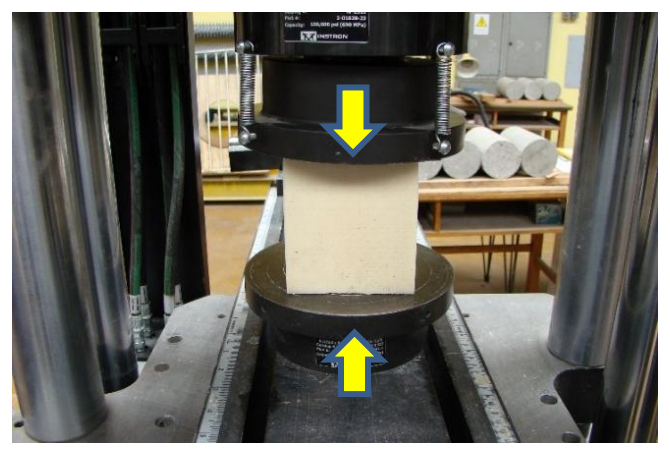
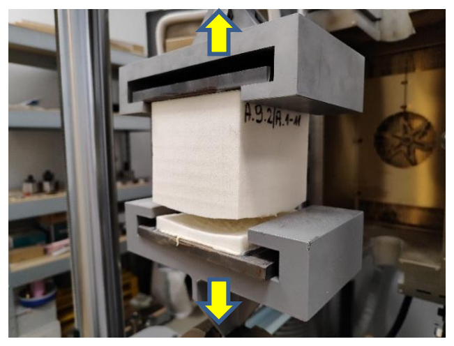
Sandwich panel cores are subjected to typical compressive and tensile tests (Fig. 1, Fig. 2). The arrows in these figures indicate the direction of force excitation. In the case of sandwich panels used in construction, the compressive and tensile strength tests are carried out in accordance with standards [25] and [26], respectively, with [27] being the reference standard for all tests.
The aim is both to determine the longitudinal moduli of elasticity of the core (in compression and tension) as well as to determine the appropriate strength. Figures 3 and 4 show examples of the σ-ε relationship for a core made of PIR foam. In both figures, trend lines have been added, which show that the compressive modulus is 3167.6 kPa, and the tensile modulus is higher and has a value of 3807.1 kPa.
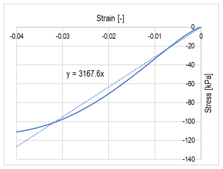
Fig. 3. Stress-strain relationship in the case of PIR foam compression: solid line - experimental data, dotted line - linear trend function (given in the figure)
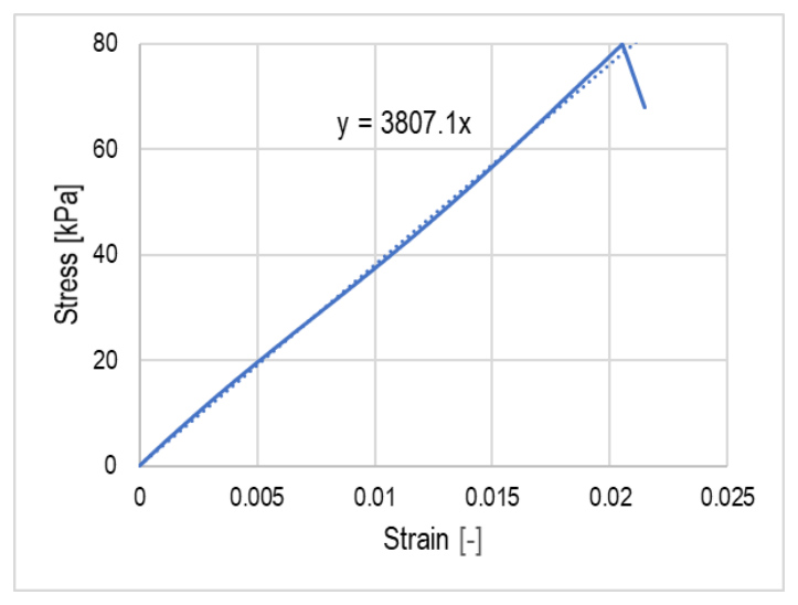
Fig. 4. Stress-strain relationship in the case of PIR foam tension: solid line - experimental data, dotted line - linear trend function (given in the figure)
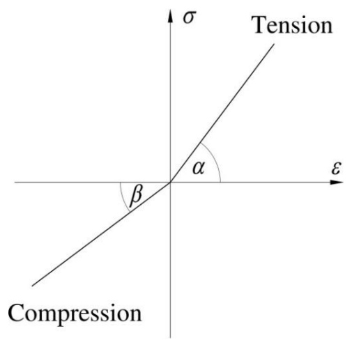
The comparison of the relationships presented in Figs. 3 and 4 shows that the behavior of the foam depends on whether it is compressed or stretched. If we ignore the nonlinearities of the σ-ε diagrams, the behavior of the foam can be simplified to the relationship shown in Fig. 5. The tangent of α corresponds to the modulus in tension, and the tangent of β is equal to the modulus in compression. The elastic range is not limited here, because it is assumed that the loss of stability occurs when the core strength is not exceeded. In the conducted analyses, it was also decided to make the shear modulus independent of the longitudinal elastic moduli, which is a very common and at the same time universal procedure. This does not mean, however, that the shear modulus cannot change. On the contrary, no relationship was introduced between the elastic moduli and the shear modulus, and therefore these values can be arbitrary. In numerical nomenclature, this means the use of the so-called engineering constants (see, [28]).
FORMULATION OF THE PROBLEM
The sandwich panel is subjected to an external load that causes compression in one of the facings. The compressed facing together with the surrounding core is considered (Fig. 6). Such a simplification is allowed when the core is so thick that deformations of one facing do not affect the other facing, which is the case in most practical cases [4-6]. Due to compression, there is a local loss of stability of the facing, which takes the form of a periodic wave. As a result of deformation, the normal stress σCz and the shear stress τCxz appear in the core.
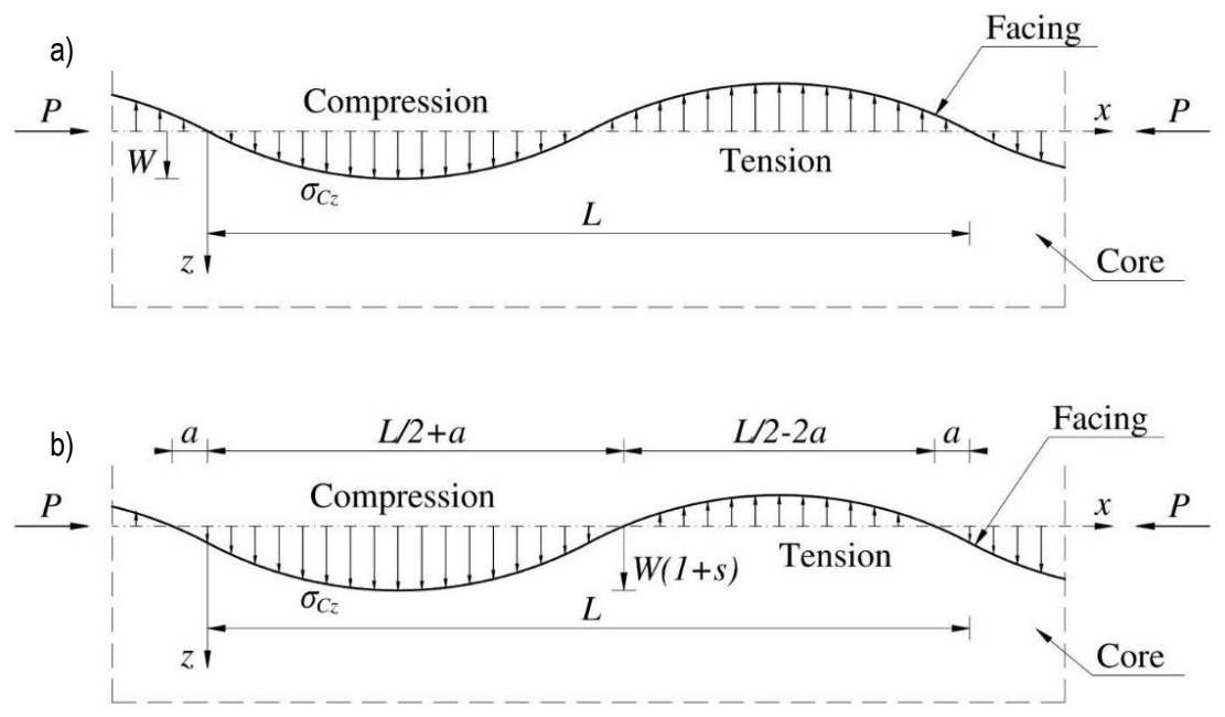
Fig. 6. Assumed deformation of the thin facing resting on the infinite core in the case of: a) the classical case of linear elasticity of the core, b) the case of non-linear constitutive relationship presented in Fig. 5
One of the basic problems is the assumption of a specific form of deformation of the compressed facing. In the classical case of a linearly elastic core (substrate), the wrinkling of facing is assumed in the form of sine function (Fig. 6a):

where W is the amplitude of the deformation and L is the full wavelength of the sine wave.
In the considered case of a substrate characterized by different compressive and tensile stiffness (Fig. 5), and therefore by different deformations in the area of core compression and tension, some modification of the deformation function is necessary. From a theoretical point of view, it is enough that wF(x) is a function of class C4 (the function and its four consecutive derivatives are continuous). Determining a function of this class that would also satisfy the additional conditions regarding inflection points is quite difficult. Therefore it was decided to approximate the solution with a shifted sine function (Fig. 6b, Eqs.(2-4)). If the compressive stiffness modulus of the core is lower than the tensile modulus, larger deformations occur in the compression zone, as shown in Fig. 6b.
DETERMINATION OF THE CRITICAL LOAD
General equations
In order to determine the critical load and wrinkling stress, the energy approach was used in this paper. The deformation of the infinite facing at the moment of buckling is

Equation (2) means that the sine function is shifted by an unknown value Ws, so s indicates a shift in relation to the sine function, the maximum value of which is of course equal to 1. Moreover, by setting that a ≥ 0 and introducing the dimensionless quantity m = a/L, one obtains:

Similarly to the approach of other authors [5, 8], it was assumed that deformations in the core decay exponentially with the increase of the variable z:

The parameter k (k > 0) introduced in (4) corresponds to the decay of the core deformation with increasing position variable z. It should be noted that the parameter k is not dimensionless, but the product kz is. The decay of the core deformation with increasing distance from the wrinkled facing is consistent with experimental observations.
The energy balance equation for the system shown in Fig. 6b can be written (per unit width and over wavelength L) as:

where

is the work of applied force P,

represents the strain energy of the facing due to bending, where BF denotes the facing bending stiffness per unit width, and

expresses the strain energy of the core, where the modulus of core elasticity ECz:

It was assumed that the core shear modulus GCxz would not depend on whether the compression or tension region was considered.
The normal stress σCz and the shear stress τCxz in the core can be find as:


Due to (9), when integrating the first expression in (8), it is necessary to take into account the separation of the integration limits over the variable x corresponding to the compression and tension zones of the core:

Energy expressions
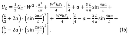
Substituting (2-4) into (6-8), using (10-11) and taking into account (12), the following energy expressions were obtained:


By substituting expressions (13-15) into (5) and reducing W2, the force P is received:
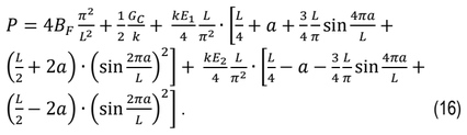
The determined force depends on material parameters of the facing and core, but also on unknown quantities a, k and L.
Solution finding procedure
To find the minimum force P that causes the buckling of facing, first derivative zeroing conditions with respect to the variables a, k and L are applied:
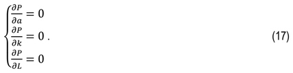
From equations (17), keeping in mind that m = a/L, the following conditions are obtained:

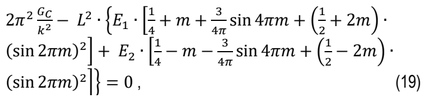
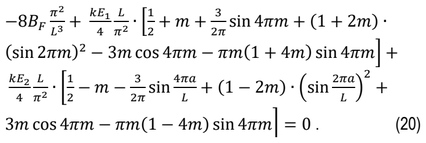
The value of m is determined from (18), and then the set of equations (19-20) is solved. It is worth noting that (20) shows that the shift of the deformation function (2) represented in (18) by m depends only on the relationship between the modules E1 and E2.
Using (20), k can be presented as a function of L, which should be substituted into (19). By determining L, parameter k and the critical force P defined by (16) are also obtained.
EXAMPLES
Example 1
A special (borderline) case is considered in which the modules in the compression and tension zones are identical EC = E1 = E2, therefore a = 0 and m = 0. Conditions (19-20) then take the form:


and the final solution is:



The value of the critical force (25) is consistent with the value given in many publications (see, [8]). For example values: BF = 2.404×10⁻³ kNm, GC = 2800 kPa and EC = 6000 kPa, the critical load is P = 64.84 kN/m. The bending stiffness BF corresponds to a typical facing with the thickness tF = 0.5 mm made of steel EF = 210 GPa, F = 0.3.
Example 2
The example is considered in which the moduli of longitudinal elasticity of the core in compression and tension differ by 10%, namely: E1 = 5400 kPa and E2 = 6000 kPa. The remaining values were determined as before: BF = 2.404×10⁻³ kNm and GC = 2800 kPa.
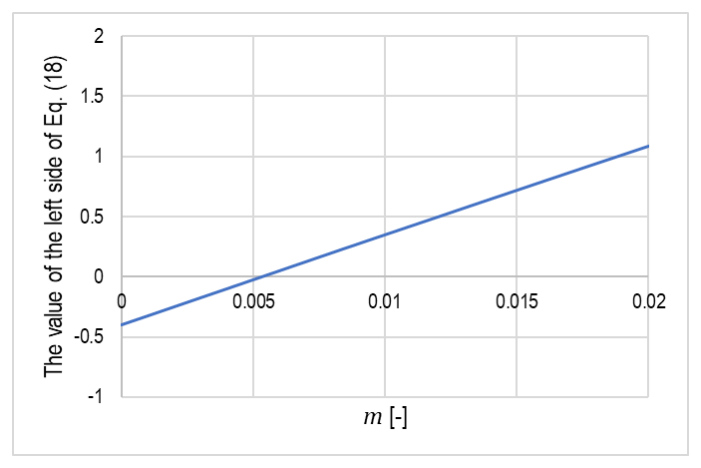
The graph of the function expressing the left side of equation (18) is shown in Fig. 7, and the solution of (18) is m = 0.0053367 [-]. This value means that the horizontal shift of the deformation function, in this case, is of the order of 0.5% of the sine wavelength, which corresponds to a vertical shift value (s) of the order of 3.35%.
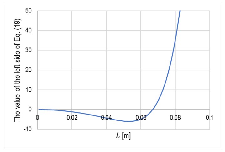
In the next step, k was expressed as a function of L based on (20) and substituted into (19). A plot of the values of the left side of equation (19) as a function of L is shown in Fig. 8.
For the given material parameters, the solution to equation (19) is L = 0.066845 [m], which corresponds to k = 65.9913 [1/m] and P = 63.69 kN/m. Both Example 2 and previous publications [3, 8] show that in principle there is no problem in determining the uniqueness of the solution. The comparison of the values presented in Examples 1 and 2 show that reducing the elastic modulus EC in the compression zone by 10% resulted in a reduction of the critical force by 1.77%. This is not much, but it is due to the fact that the buckling of the facing is influenced not only by the energy of normal deformations of the core, but also by the energy of the core shear deformation (related to GC) and the deformation energy of the facing itself (related to BF).
Example 3 – parametric study
In order to illustrate the influence of the different modulus of longitudinal elasticity of the core in compression on the value of the critical force, calculations were made using a different level of reduction E1 in relation to E2. The remaining parameters were assumed as before: BF = 2.404×10⁻³ kNm, GC = 2800 kPa and E2 = 6000 kPa. Figure 9 shows a graph of the dependence of the critical force P on (E2-E1)/E2.
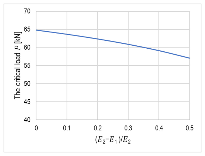
Figure 9 illustrates an obvious relationship that as the E1 module decreases, the critical force decreases, and this relationship is slightly non-linear. By the way, it can be added that the smaller the module, the longer the wavelength L. Reducing E1 modulus by 50% resulted in a reduction of the critical force (and therefore the wrinkling stress) by about 12% (P = 57.07 kN/m).
CONCLUSIONS
The problem of local instability of a thin facing resting on a shear-deformable core was considered. Due to the slightly different behavior of the core of the sandwich panel in the compression and tension zones, two moduli of longitudinal elasticity of the core material were distinguished. Because of the different stiffnesses of the core, it was assumed that the facing deformation function may have the form of a shifted sinusoid.
The most important effect of this work is the derivation of equations that allow for the determination of the critical force causing the loss of stability of the facing resting on the above-described substrate. The energy method was used to derive the equations. The obtained solutions are illustrated with examples, which also explain the procedure used to obtain the solution.
The results indicate that the physical nonlinearity of the core, previously neglected in the literature, influences the local loss of stability of the compressed facing. For a 10% difference in the core's longitudinal elastic moduli (the difference between compression and tension), the difference in the critical force is 1.77%. A 50% difference between the moduli means a 12% change in the critical force, assuming a constant core shear modulus. In reality, as the difference between the core's longitudinal elastic moduli increases, its shear modulus will likely also change as well, amking the change in critical load more significant.
The derived equations allow for the assessment of the sensitivity of the critical force to changes in the material parameters of the core and facing. The presented approach has its limitations, particularly related to the assumed nature of the physical relationship for the core material and the assumed homogeneity. Further work could simultaneously consider material inhomogeneities combined with a more general form of physical nonlinearity of the core material.