
INTRODUCTION
Accidents in everyday human activity have always been and continue to be, an inherent part of both individual and societal functioning. The need to protect the human head from mechanical injuries has long been recognised. Historically, this need arises primarily from the use of armour to protect warriors from military weapons. With civilisational progress, the attention has moved toward protecting the human body from mechanical injuries in a broader context. The human head is highly sensitive to dynamic loads and is difficult to protect due to the random nature of possible accident scenarios. Current research in head protection can be categorised into four areas:
Experimental studies aimed at determining the mechanical properties of biological tissues, materials, structures, and components.
Experimental investigations of complete objects, focussing on overall mechanical behaviour.
Analytical research, including the development of material models and models of relevant physical phenomena.
Simulation-based studies, which allow rapid analysis of multiple variants of a problem.
The integration of these research areas is essential. Currently, none can operate independently. Combining scientific disciplines and research methods produces rational outcomes and identifies directions for future development. Monea et al. [8] reviewed 15 years of literature on bicycle accidents and head injuries. They reported that head impacts are most frequently caused by skull fractures, subdural haematomas, and brain contusions. The energy criteria for the fracture ranged from 22 to 24 J for the frontal bone and from 5 to 15 J for the temporal bone. Tolerance levels for rotational accelerations of the head have been estimated at approximately 10,000 rad/s², assuming load impulses of less than 10 ms. Exceeding this threshold can lead to an acute subdural haemorrhage due to blood vessel rupture. Head protection is closely related to the relative motion between the brain and the skull, which can generate secondary dynamic loads under certain conditions. Stark et al. [21] highlighted inconsistencies between different head models used in experimental helmet tests. At high linear impact velocities, friction between the head and helmet lining becomes significant. Trotta et al. [24] studied sliding properties between the scalp and skull, as well as between the scalp and the helmet lining, using human cadaver heads. Yoganandan et al. [23] conducted impact tests on human heads, instrumented with accelerometers, in which the temporal–parietal region struck an anvil with a force sensor at varying velocities. These tests provided maximum values of the impact force, bone displacement, acceleration, and energy-related indicators, as well as parameters to estimate the head injury criterion (HIC). Verschueren [1] analysed head injuries in his doctoral research. This study forms the basis for ongoing work to improve protective helmet design. Original experiments using a pendulum apparatus were conducted to study macroscopic and micro-skull damage. Impact tests were used in the frontal region of the human head to assess biomechanical tolerance, considering skull fractures, subdural haematoma, diffuse axonal injury, and brain contusion. Based on the studies by Verschueren et al. [1, 5] and current research, a methodology for evaluating head protection absorbers was developed. This methodology is registered as patent application No. P.453213 with the Patent Office of the Republic of Poland. A comprehensive approach requires testing bone tissue and applying a modified superposition method to determine the equivalent stiffness of the head–helmet or neck–head–helmet system.
Sahoo et al. [11, 22] improved a human head model to simulate head injuries using the finite element method (FEM). The model was validated using data from experimental cadaver studies. Various mechanical indicators were analysed to evaluate bone tissue injury. The energy criterion was identified as the most accurate predictor of skull fractures, while the HIC was found to be unsuitable for lateral head impacts. The impact velocity and the stiffness of the striking object had a greater effect on the impact force than the geometry of the striking surface or impacted area. Sbriglio et al. [29] reviewed computational modelling of head injuries. Li et al. [19] and Wilhelm [32] discussed FEM simulations of child head models, highlighting variations in the mechanical properties of bone tissue with loading direction. Virtual models of newborn and newborn heads (5- and 9-months) were subjected to impact simulations across the forehead, occipital bone, vertex, and parietal regions, including skull compression tests. Obst et al. [13] reviewed motorcycle helmet testing procedures, highlighting differences in approval methods and test protocols. The dynamic relationship between head and neck stiffness was emphasised. Fernandes et al. [33] summarised knowledge on helmet design, testing, and effectiveness in preventing head injuries. Curnow et al. [31] questioned the protective effect of helmets on brain injury and critiqued assumptions from previous studies. Meng [18] identified inaccuracies in evaluating rotational effects and recommended updates to helmet testing standards. Li et al. [3] proposed FEM-based methods to assess helmet protective performance. Experimental tests involved helmet drops with accelerometer-equipped headforms (ECE 22.05). Maximum acceleration, HIC, and biomechanical parameters such as intracranial pressure and Huber–Mises stress were measured. Helmet liner geometry and foam density optimisation improved protection ratings.
Zhou et al. [2] modelled child head impacts using FEM and validated the results against cadaver data from static and dynamic tests. High agreement was observed for the acceleration and head deflection measurements. Huber– von Mises - Hencly stress analysis was performed and injury indices (HIC, BrIC, HIP) were estimated to assess accident risk. Li et al. [4] applied translational acceleration to head models to study brain tissue loads, intracranial pressure, Huber–Mises stress, and head deformation. The duration affected stress and deformation, while intracranial pressure remained independent of the duration of the load. Yazıcı et al. [15] tested head impacts on foam-covered car hoods, simulating pedestrian accidents. HIC was used to evaluate the results. Deck et al. [6] proposed methods to assess the effectiveness of motorcycle helmets under realistic impact conditions. Wang et al. [7] conducted biomechanical studies on nine bicycle helmets to validate FEM models. Mosleh et al. [14] emphasised the effects of rotational acceleration during oblique impacts and proposed anisotropic composite foam for helmet liners and car headliners to mitigate rotational loads. Anisotropy was achieved by layering EPS foams of varying density. The injury indices HIC, HICrot and HIP were used to evaluate the foam. Li et al. [9] developed layered foam impact tests (FGF) for helmet protection using FEM. Obst et al. [12] examined LDPE pneumatic absorbers in two shock scenarios: with free air flow and sealed. Mechanical dynamic characteristics were established for both cases, supporting potential use as energy-absorbing elements in collisions. Spinelli et al. [10] proposed adaptive helmets for construction workers using flexible materials that respond to the rate of deformation. Ptak et al. [30] studied the behaviour of cork impact with attention to strain rate and temperature. Varela et al. [16] addressed head injuries in contact sports and suggested energy-absorbing headbands made of agglomerated cork for environmental and ecological benefits. Tomita et al. [20] developed nonlinear FEM models of auxetic structures to absorb impact energy. Catena et al. [17] reconstructed a motorcyclist accident involving complex head injuries. A subarachnoid haemorrhage and multiple skull fractures were observed, including facial bones. Death resulted from an impact with a road bolt that penetrated the helmet and skull, highlighting the risks posed by the elements of the infrastructure.
Despite extensive research on conventional foam-based impact absorbers, pneumatic structures with controlled air flow remain largely unexplored in the context of head protection systems. In particular, the application of LDPE pneumatic absorbers as impact energy dissipating elements represents a novel approach, enabling tunable mechanical behaviour through regulated air release. This study presents, for the first time, a systematic experimental investigation of LDPE pneumatic absorbers subjected to dynamic impact loading, in which the effects of air flow rate, ventilation configuration, and vent hole diameter on energy dissipation, stiffness, and damping characteristics are quantitatively assessed.
Furthermore, the proposed research methodology allows for a direct comparison between pneumatic absorbers and conventional EPS100 polystyrene foam under equivalent volumetric conditions, which has not been previously reported. By establishing dynamic characteristics and air flow–dependent diagnostic indicators, the study provides new insights into the design of adaptive impact mitigation systems with adjustable protective performance. The results demonstrate the potential of LDPE pneumatic absorbers as an innovative and scalable alternative to traditional foam-based solutions for head protection and other critical safety applications.
The specific objectives of this research are: (1) experimental testing of pneumatic impact absorbers under controlled conditions, (2) processing and analysis of results using approximation functions, (3) development of dynamic characteristics for pneumatic and polystyrene absorbers, and (4) comparative evaluation of protective effectiveness between pneumatic LDPE and EPS100 polystyrene absorbers.
MATERIALS AND METHODS
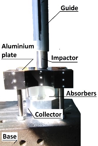
Impact tests of LDPE pneumatic absorbers and EPS100 polystyrene absorbers, matched in terms of volume and geometry, were performed using an inertial test rig, commonly referred to as a drop tower (Fig. 4). The test conditions were identical for all absorbers, including a test temperature of 23°C, impactor weight, and drop height. The pneumatic absorbers (Figs. 1 and 2) were placed and fixed with thermal silicone parallel to an aluminium collector plate equipped with internal channels. This arrangement allowed the impact to compress the air within the common volume of the absorbers and the collector. In each experiment, five pneumatic absorbers were tested simultaneously.
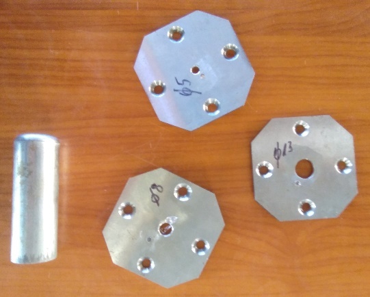
The tests included fully sealed systems, systems with controlled air flow, and fully open configurations. In sealed systems, the aluminium collector was closed with a cover without openings. For throughflow systems, air flow from the absorber was regulated using openings with diameters of 5, 8, 10, and 13 mm (Figs. 2 and 3). Different air flow rates were achieved by employing interchangeable sealed plates with a centrally located hole (Fig. 3).
The testing methodology for EPS100 polystyrene absorbers (Fig. 1b) was analogous to that used for LDPE pneumatic absorbers, except that no aluminium collector was used. Sets of pneumatic or polystyrene absorbers were placed beneath the aluminium bumper plate of the drop tower and dynamically loaded with a steel impactor weighing 0.275 kg, which was dropped from heights of 0.2, 0.3, 0.4, and 0.5 m. The heights of the impactor drop were determined based on preliminary observations of the performance of the pneumatic absorbers under dynamic loading conditions. Excessive impact velocities caused the absorbers to reach a state of full compression. Furthermore, the selected impact velocities represent the boundary between conditions considered acceptable and those potentially hazardous to human health and safety. The impactor mass was chosen according to the same criteria. A steel impactor striking an aluminium plate weighing 0.942 kg, mounted on linear ball bearings and guided along rods with negligible resistance, transferred the energy of the elastic impact to the plate, which in turn dynamically loaded the tested absorbers. The motion of the aluminium plate was recorded using a Chronos 2.1 HD high-speed camera and displacements were measured as a function of time. Data were acquired at a frame rate of 7135 fps, providing a sufficient number of measurement points within the tested range. The displacement results obtained from multiple tests were averaged and subsequently approximated using a modified three-parameter family of sine functions. This analytical description of the experimental characteristics enabled the derivation of additional mechanical parameters, which constitute the primary objective of this study.
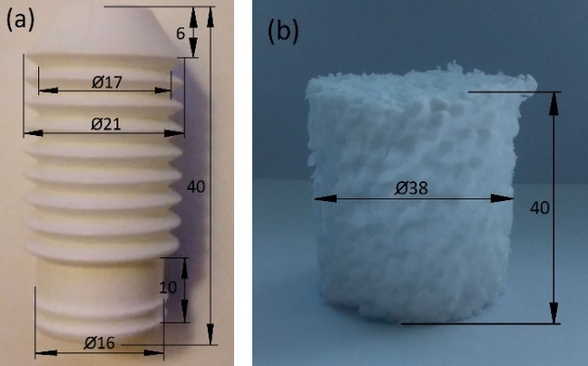
Fig. 1. (a) LDPE pneumatic absorber, (b) EPS100 polystyrene absorber, adequate in terms of volume and geometry for five LDPE pneumatic absorbers
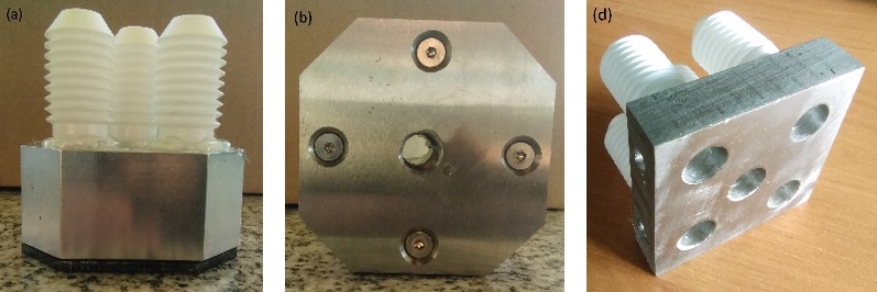
Fig. 2. Aluminium base, collector to test LDPE absorbers (a). View of the manifold from the side of the replaceable plate with a 10mm diameter opening (b). View of the through collector (c)
Analytical considerations were made on the following assumptions:
Impact of a steel impactor on an aluminium plate is treated as quasi-elastic. The tested configurations were classified as simple central collision cases.
Contact surfaces are ideal bonds (the impactor contact surface is a little rough); no tangential forces act on them.
A set of five parallel LDPE pneumatic absorbers was selected because such devices typically operate in groups in practice.
The displacement results obtained using the Chronos 2.1 HD high-speed camera were averaged from five measurements for each case under the same experimental conditions due to the similarity of their characteristics and the purpose of their analytical description.
Experimental Data Approximation
Approximations of all experimental dependencies of the dynamic lowering of the pneumatic absorber package over time, in the progressive phase (increase in displacement x(t) until its maximum value is reached), were made using a family of functions of the following form.

where b [mm], c [s⁻¹] and n are parameters that affect, respectively: the amplitude, period, and shape (especially the convexity) of the approximating function.
The degressive phase (return of absorbers to their initial state), depending on the experimental results obtained, was approximated using a function from family (1) (however, with approximation parameters generally different from those for the progressive phase) or by using a linear function:

with constants g [mm/s] and h [mm] ensuring continuity and consistency of the approximation with the experimental characteristics.
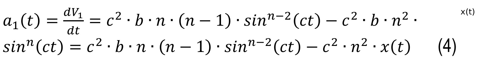
The main characteristics under consideration, i.e., velocity V1(t) and acceleration a1(t), occurring up to the moment of maximum displacement of the absorber package, were determined using relationships based on formula (1):

and:
To determine (critical due to the designation of the attenuation T of the absorber system) the velocity V2 in the degression phase (decrease in absorber displacement), formula (3) or the relationship of the form:

Having initial speeds V₀ = V₁(0) and final Vₑ = V₂(t*) (achieved at the end of the absorber operation time), the damping coefficient of the system was determined by defining it using the relationship:
t* - designation of the time at which the absorbers return to their original shape.
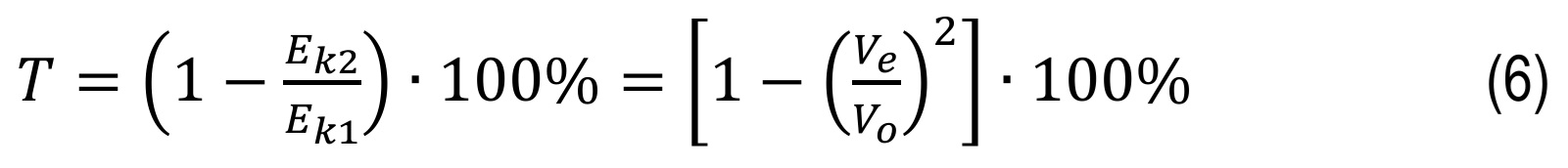
where Eₖ₁ and Eₖ₂ determine the kinetic energies of the plates at the beginning and end of the absorber’s operation, respectively.
The resistance force of the absorber system, depending on its deflection, was determined using the relationship based on the second principle of dynamics and formulas (1) and (4):
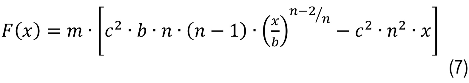
where m [kg] is the mass of the plate loading the absorbers. Using the classical definition of stiffness C(x) as the first derivative of force with respect to deflection, we obtain the following.
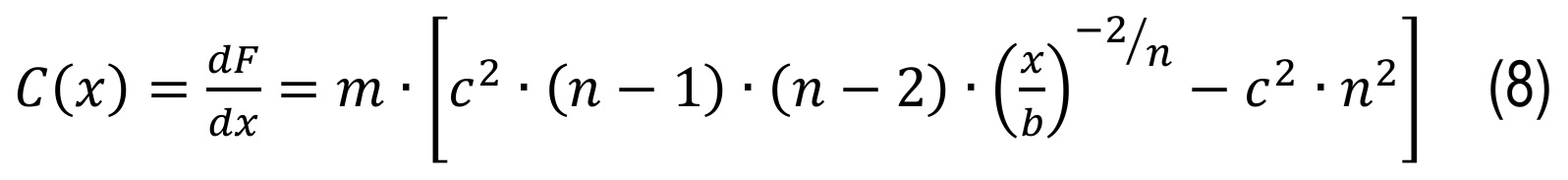
It is worth noting that for n=1, the stiffness is constant and equal to c2. The convexity of the function describing the characteristic xt can be a useful indicator in assessing the effectiveness of the tested absorber, determining the change in dynamic stiffness Cx within a strictly defined time interval. The quality of the measurement results and their processing for the purpose of performing calculations is very important.
LDPE pneumatic absorber experimental tests
Five sealed LDPE pneumatic absorbers were arranged in parallel on an aluminium manifold and fixed with thermal silicone (Fig. 2a). The collector space was sealed with a tight cover plate equipped with a rubber gasket to prevent air escape during testing. Flow-through absorber tests were performed using a collector with channels and openings to allow air to exit the absorbers (Fig. 2c). LDPE pneumatic absorbers with restricted air flow through openings of specified diameters were tested in the same systematic manner. The channels within the aluminium manifold were designed to vent air externally while minimising their total volume and, consequently, their influence on the pressure change rate inside the absorbers during impact. The geometry of the manifold also accommodates the installation of sensors such as pressure and temperature sensors. Using data recorded with a Chronos 2.1 HD high-speed camera, derivative characteristics were derived, including velocities, accelerations, forces, dissipated impact energy, stiffness, damping, and air flow intensity. Experimental displacement data was averaged over five tests for each configuration and subsequently approximated as a function of time. The approximated displacement characteristics for LDPE absorbers are presented in Figs. 5 and 10.
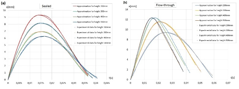
Fig. 5. Results of the experimental displacement tests and their approximations for five (a) sealed and (b) LDPE pneumatic flow-through absorbers
Characteristics (a) and (b) (Fig. 5) show the results of displacements as a function of time (solid lines) and their approximations (dotted lines) for two extreme cases of tested LDPE pneumatic absorbers, that is, in the case of sealed absorbers (a) and flow-through (b). Different displacement values for sealed and free through absorbers at different speeds and impact energies. The time required to achieve maximum displacement is noteworthy, which for sealed absorbers is approximately 0.015 s for all impactor drop heights, while for through-type absorbers it ranges from 0.015 s for higher impact energy values and approx. 0.02 s to 0.025 s for lower impact energy values. The displacement time and its value indirectly constitute a biomechanical indicator that can be interpreted as the course of the braking process. A longer brake distance that requires more time is crucial to protect the human head from the consequences of impulse loads, resulting in the minimisation of adverse overloads causing mechanical injury.
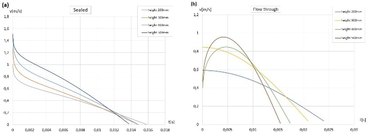
Fig. 6. Results of experimental speed tests for five (a) sealed and (b) LDPE pneumatic flow-through absorbers
Characteristics (a) i (b) (Fig. 6) for sealed and free air through-type LDPE pneumatic absorbers; They are a measure of the indicator speed at which the tested impact absorbers dissipate the kinetic energy of an aluminium bumper plate. In the case of sealed absorbers (characteristic (a), Fig. 6), the curves are similar for the four impactor drop heights. In the initial phase of operation of sealed absorbers, a period of intense velocity decay is visible, occurring in a very short time, approx. 3∙10-4s. This is an unfavourable phenomenon that results in high acceleration values, which cause head injuries. LDPE through-type absorbers (characteristic (b), Fig. 6) are characterised by a gentler acceleration over a longer period of time, which is beneficial from the point of view of human head biomechanics. At higher impact energy values (300 and 400 mm impactor drop height), intense velocity increases in the initial phase of the impact (duration up to approx. 0.005 s) are predominant. This is an undesirable phenomenon, although the duration of the increase in speed is within a range that is biomechanically acceptable for humans. Furthermore, the indicated intensive increase in velocity for through-type pneumatic absorbers may be caused by a mechanism related to the geometry of the absorber and the mechanics of LDPE plastic, whose mechanical properties depend on the velocity of deformation Obst [25].
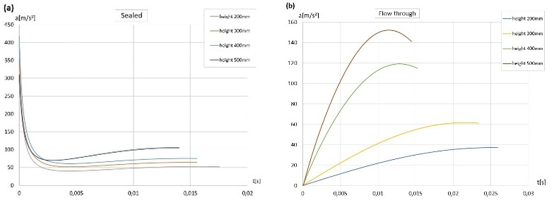
Fig. 7. Results of experimental acceleration tests for five (a) sealed and (b) LDPE pneumatic flow-through absorbers
The acceleration characteristics of the sealed and flow-through pneumatic absorbers (a) and (b) (Fig. 7) show clear differences in the operation of both extreme cases. Sealed pneumatic absorbers exhibit very high acceleration values in the initial phase of impact (duration approx. 0.002 s), then this is followed by a reduction in the acceleration to values ranging from approximately 5 to 10 g, acting within hundredths of a second. The case of pneumatic through-type absorbers (Fig. 7b) is characterised primarily by significantly lower acceleration values compared to sealed-type absorbers. The peak acceleration values obtained for higher impact speeds appear to be unfavourable, as their duration of action in relation to possible overloads is not biomechanically advantageous.
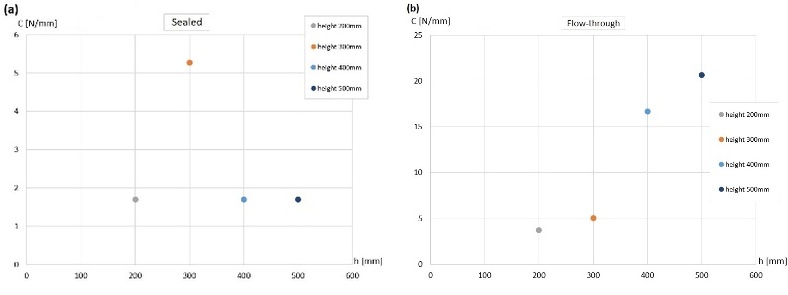
Fig. 8. Stiffness as a function of the height of the impactor drop: 0.2 m, 0.3 m, 0.4 m, and 0.5 m for five (a) sealed and (b) LDPE pneumatic flow-through absorbers
Stiffness is an important mechanical indicator used in the evaluation of materials and structures. Stiffness indices for sealed and through-type pneumatic absorbers (a) and (b) (Fig. 8) show, above all, that the resulting stiffness of a pneumatic absorber depends on many factors, including the deformation speed and impact energy. Sealed absorbers are relatively rigid, which is disadvantageous in terms of the biomechanical conditions of the protected head. The flow-through pneumatic absorber, which operates mainly on the geometry of the coating and the mechanical properties of the LDPE plastic, exhibits more favourable stiffness values under test conditions.
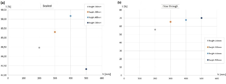
Fig. 9. Impact energy absorption of five LDPE pneumatic absorbers as a function of impactor drop height: 0.2m, 0.3m, 0.4m, and 0.5 m - results obtained for (a) sealed and (b) LDPE pneumatic flow-through absorbers
The T attenuation coefficients for the sealed and open absorbers (a) and (b) (Fig. 9) are a measure of the dissipation of impact energy. In the case of sealed absorbers, a linear relationship is visible for attenuation in the speed range up to 2.8 m/s, while attenuation indicators range from approximately 88 to 90%. Higher impact energy and speeds above 3 m/s result in a decrease in the damping properties of sealed absorbers of approximately 87%. The performance of the flow-through pneumatic absorber is characterised by relatively stable attenuation in the range of approximately 55% to 70% across the range of impact speeds tested.
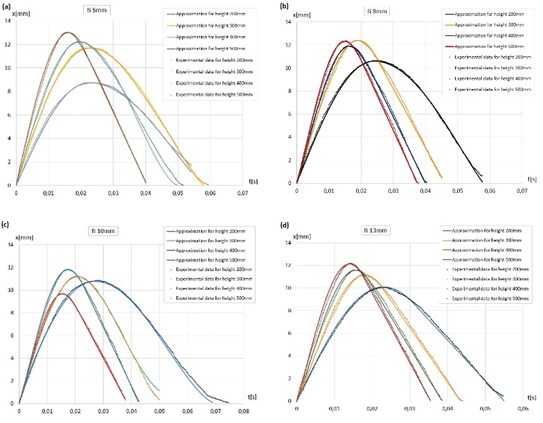
Fig. 10. Results of the experimental displacement tests x(t) and their approximations for five LDPE pneumatic absorbers with a flow restriction plate with a throttling hole diameter of (a) 5 mm, (b) 8 mm, (c) 10 mm, and (d) 13 mm
Characteristics (a-d) (Fig. 10) show the results of displacements as a function of time (solid lines) and their approximations (dotted lines) for LDPE pneumatic absorbers with air throttling by holes with diameters of 5.8, 10, and 13 mm, respectively. In all cases, attention is drawn to the maximum displacement value, which fluctuates around 12 mm. Absorbers with a 5-mm diameter hole showed the highest maximum displacement value of 13 mm and the lowest minimum displacement value of approximately 9 mm. There are visible differences in the duration of displacement. Increasing the diameter of the throttling hole generally results in shorter braking times.
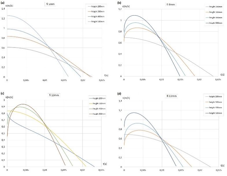
Fig. 11. Speed results v(t) obtained based on displacement approximations x(t) for five parallel LDPE pneumatic absorbers with a throttling hole diameter of (a) 5 mm, (b) 8 mm, (c) 10 mm, and (d) 13 mm
The velocity characteristics (a-d) (Fig. 11) for pneumatic absorbers throttled with holes of different diameters show similar maximum velocity values and similar minimum values. Differences are visible in changes in speed values and their change time. Absorbers with a 5-mm diameter throttle hole are the most advantageous in this case. The speed changes occur smoothly, and in the case with the highest impact energy, the time interval is the longest.
The acceleration characteristics of LDPE pneumatic absorbers throttled with plates with holes of various diameters (a-d) (Fig. 12) indicate that a hole with a diameter of 5 mm is the most advantageous. It should also be noted that the acceleration curve for a 10 mm hole diameter when struck from a height of 200 mm differs from the others (Figs. 12-c). The reasons for the estimated acceleration values can be found in errors resulting from the approximation of displacement characteristics and the differentiation of analytical functions to estimate acceleration. Despite the inconveniences of the methodology, the proposed system appears to be valuable for evaluating the impact energy absorbers under investigation. Figure 13 shows the relationship between the estimated accelerations for the sealed absorbers and the flow throttled by holes of various diameters from the height of the impactor drop. The relationships obtained are not linear with respect to the individual heights of the impactor drop. Interestingly, the highest accelerations were obtained for the throttling plate with a hole with a diameter of 13 mm, while the greatest accelerations were determined for the sealed absorber, where in both cases the hammer fell from a height of 500 mm. Therefore, it can be concluded that the most advantageous absorber in terms of accelerations would be one equipped with an adaptive valve that adjusts the air flow rate to dynamic load conditions.
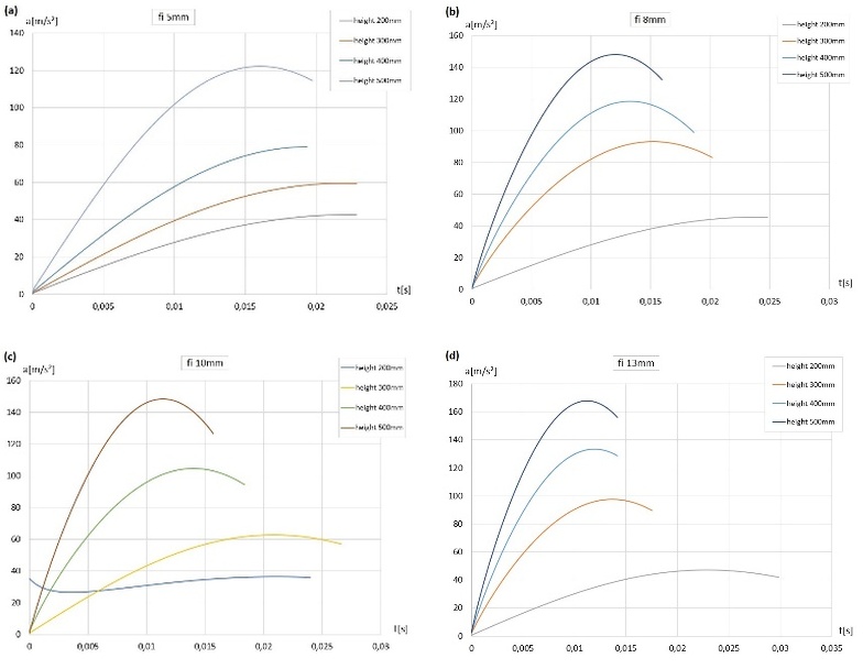
Fig. 12. Acceleration results a(t) obtained based on displacement approximations x(t) for five parallel LDPE pneumatic absorbers with a throttling hole diameter of (a) 5 mm, (b) 8 mm, (c) 10 mm, and (d) 13 mm
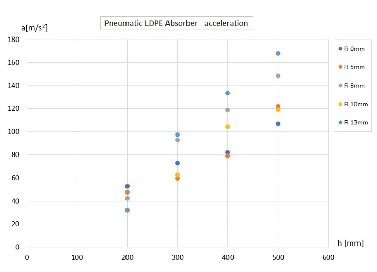
Fig. 13. Compiled maximum acceleration results a(t) obtained based on displacement approximations x(t) for five parallel LDPE pneumatic absorbers with a throttling hole diameter of: 0 mm, 5 mm, 8 mm, 10 mm, and 13 mm
The stiffness characteristics for pneumatic absorbers with flow throttled by plates with holes of various diameters are shown in Fig. 14 (a-d). For a hole with a diameter of 5 mm, pneumatic absorbers are the most rigid. There is also a noticeable trend for decreasing stiffness as the diameter of the air vent increases.
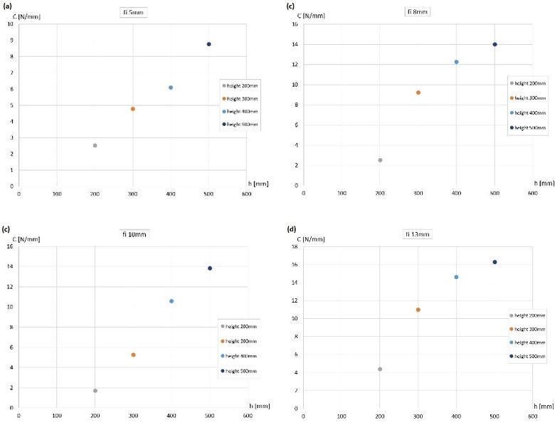
Fig. 14. Stiffness of five LDPE pneumatic shock absorbers as a function of their deflection for impactor drop height: 0.2 m, 0.3 m, 0.4 m, and 0.5 m for (a) hole fi 5 mm, (b) hole fi 8 mm, (c) hole fi 10 mm, and (d) hole fi 13 mm
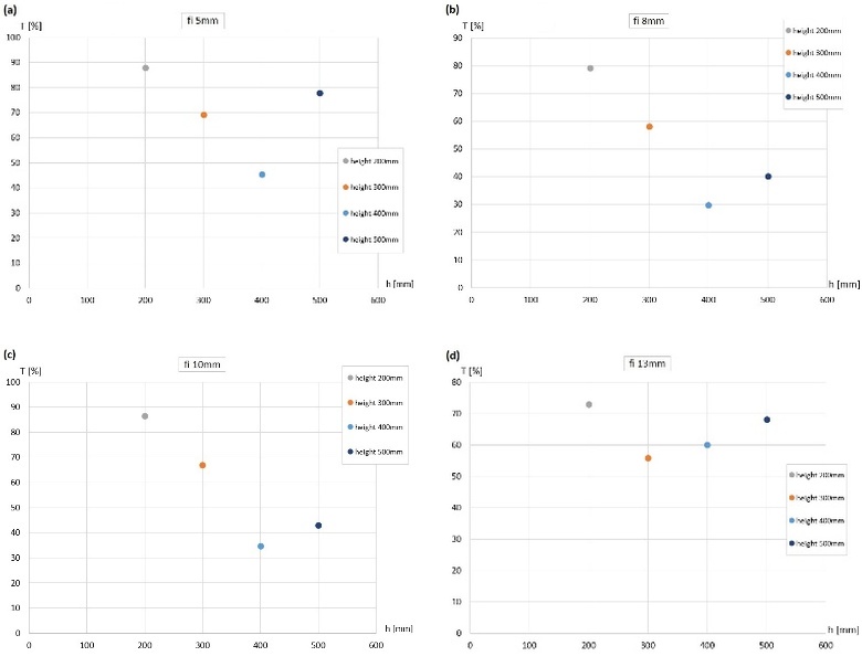
Fig. 15. Impact energy absorption of five LDPE pneumatic absorbers as a function of their deflection for the height of the impactor drop: 0.2 m, 0.3 m, 0.4 m, and 0.5 m for (a) hole fi 5 mm, (b) hole fi 8 mm, (c) hole fi 10 mm, and (d) hole fi 13 mm
The T attenuation coefficients for a pneumatic absorber throttled with plates with holes of various diameters (a-d) (Fig. 15), which are measures of the dissipation of impact energy, are characterised by interesting relationships with respect to energy and impact velocity. At low speeds of around 2 m/s, pneumatic shock absorbers with a 5 mm diameter hole dissipate almost 90% of the energy. Furthermore, for all impactor drop heights, airflow through a 5mm diameter hole has the highest impact energy dissipation capacity. Interestingly, each case, that is, the diameter of the aperture and the height of the impactor drop, showed that the energy dissipation capacity decreases and then increases. There is a threshold for changes in the damping coefficient in the speed range of 2.4-2.8 m/s. The reasons for this can be found in the properties of the LDPE material and, possibly, in the geometry of the vent hole. The plates used had sharp edges that were not shaped, especially for air flow. Therefore, it seems appropriate to conduct further research on the optimal geometry of the ventilation opening edge and the geometry of adaptive valves.
Experimental testing of EPS100 polystyrene foam
Samples of the EPS100 polystyrene absorber (Fig. 1b) were made in a cylindrical shape by cutting the desired shape out of a polystyrene board. The geometry of the cylindrical samples was based on a volume equivalent to five LDPE pneumatic absorbers. The height of the cylindrical polystyrene samples, equivalent to the height of the LDPE pneumatic absorber, was also retained. The geometry of the polystyrene sample also ensured that the stability requirement was met during impact testing. Similarly to the tests carried out on LDPE pneumatic absorbers, the impact load on the polystyrene sample was obtained by striking an aluminium plate with a steel impactor weighing 0.275 kg. Five measurements were taken for each drop height. Each EPS100 polystyrene sample was replaced with a new one after five blows to the impactor from a given height. No significant changes in displacement characteristics were observed when striking the same sample several times. Further research is planned to reveal the impact of secondary loads on the impact protection properties and durability of the absorbers tested. The experimental results of impact tests on EPS100 polystyrene foam and their approximations obtained on the basis of a modified sine function (1.1) are compiled below.
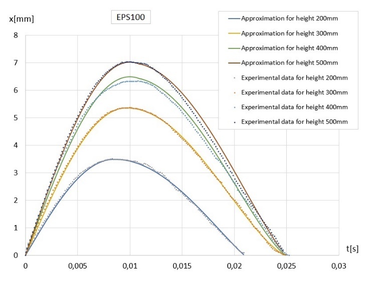
Fig. 16. Results of the experimental displacement tests and their approximations for EPS100 polystyrene absorber
The displacement characteristics of the EPS100 polystyrene absorber (Fig. 16) show lower displacement values compared to the closed LDPE pneumatic absorber (max. greater than 9 mm) and the through-type absorber (maximum greater than 12 mm) for all impactor drop heights. Furthermore, the displacement time for a polystyrene absorber is longer, both from the start of the process to the maximum displacement value (approximately 0.010 s for EPS100 polystyrene compared to approximately 0.015 s for LDPE pneumatic absorbers also with throttled airflow plates), as well as the entire recorded displacement.
The EPS100 polystyrene absorber is characterised by gentle velocity curves (Fig. 17), while the time values are lower compared to the LDPE pneumatic absorbers in each tested configuration. A longer speed reduction time is beneficial from the biomechanical point of view of the human head.
Accelerations in the case of the EPS100 polystyrene absorber (Fig. 18) reach higher values compared to the results obtained for sealed and through-type LDPE pneumatic absorbers (Fig. 7). The gentle acceleration curves for the EPS100 polystyrene absorber are noteworthy. When comparing the acceleration values for the EPS100 polystyrene absorber with the acceleration values for the LDPE pneumatic absorber with air flow attenuation using plates with holes of various diameters (Fig. 12), it can be seen that each variant tested of the pneumatic absorber is more advantageous in terms of acceleration curves compared to the acceleration curves shown in Fig. 18.
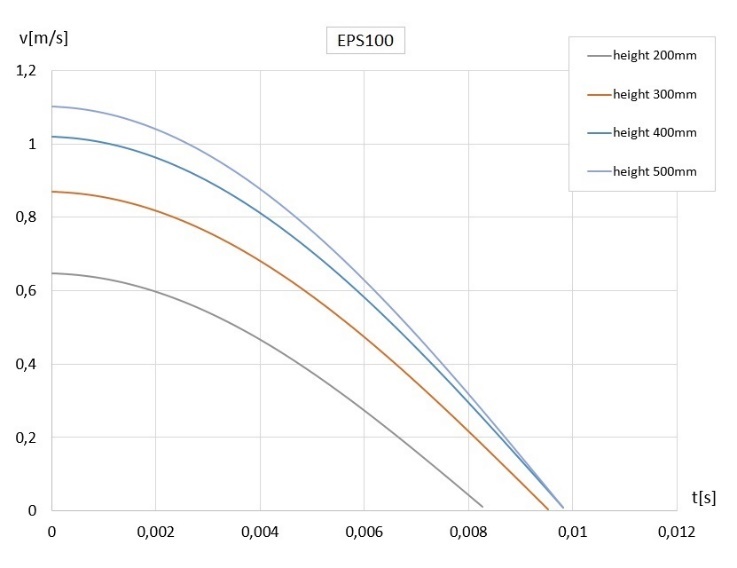
Fig. 17. Speed results obtained on the basis of displacement approximations for EPS100 polystyrene absorber
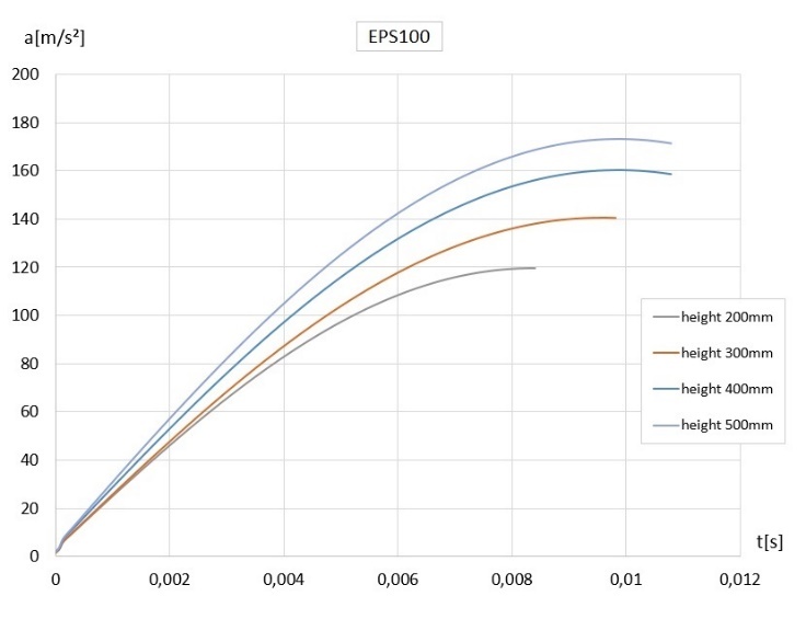
Fig. 18. Acceleration results obtained on the basis of displacement approximations for EPS100 polystyrene absorber
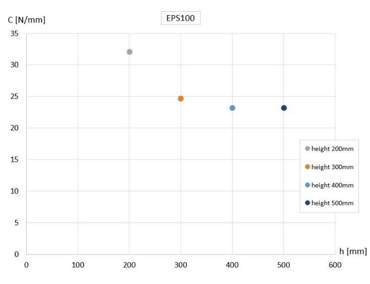
The stiffness index for the EPS100 polystyrene absorber (Fig. 19) is higher for lower impactor drop heights; then a decrease in stiffness is visible, followed by stabilisation at level 23 N/mm.
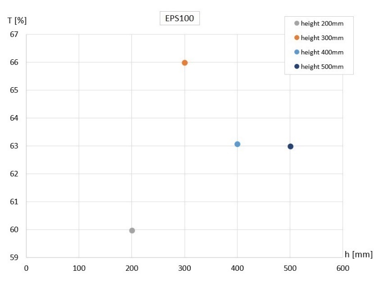
The EPS100 polystyrene absorber showed the highest attenuation value, 66%, at an initial deformation velocity of 2.43 m/s. This means that impact attenuation (i.e. the intensity of impact energy dissipation) by a polystyrene absorber depends on the deformation speed or structural changes that have occurred. The slight difference in attenuation values relative to the neighbouring points at a height of 300 mm is also noteworthy. Attenuation would be expected to stabilise after exceeding the critical impact velocity. This may be due to approximation errors.At speeds ranging from 2.8 to 3.13 m/s, the tested polystyrene absorber showed a slight change in attenuation relative to the initial deformation speed. When comparing the damping capabilities of EPS100 polystyrene absorbers with LDPE pneumatic absorbers, the values are as follows: EPS100 polystyrene absorber, range 60-66%, sealed pneumatic absorber, range 87.3-90.3%, pneumatic flow-through absorber approx. 60-70%, pneumatic absorber with a 5mm diameter hole, range 45-88%, pneumatic absorber with an 8mm diameter hole, range 30-80%, pneumatic absorber with a 10mm diameter hole, range 35-88%, pneumatic absorber with a 13mm diameter hole, range 56-73%. In summary, the dissipation capabilities of the EPS100 polystyrene absorber are comparable to those of a pneumatic flow-through absorber. A sealed pneumatic absorber works best in terms of energy dissipation. Furthermore, it can be observed that as the diameter of the aperture in the plate increases, the impact energy dispersion indicator decreases.
Analytical Study of LDPE Pneumatic Absorbers with Flow-throttling
The test stand used in the testing of LDPE pneumatic absorbers and EPS100 polystyrene absorbers allows tests that take into account the interaction between the absorbers tested simultaneously. This is an advantage that allows you to evaluate the average response of the hit absorbers. However, the problem is the difficulty in accurately analysing the parallel arrangement of LDPE pneumatic absorbers connected to a collector equipped with a plate with an airflow throttling hole. Therefore, the decision was made to use reverse engineering, where a phenomenological description of the phenomena studied was proposed.
During impact tests using a high-speed camera, the following acceleration was indirectly recorded (using analytical relationships based on functions that approximate experimental data) of an aluminum plate with a mass of m₁, obtaining a time-dependent relationship a(t). Referring to Newton's second law of motion, we can write:

where F(t) is the instantaneous resistance force exerted by the absorber.
Referring to the definition of pressure, it is correct to say:

where: A₀ denotes the cross-sectional area of the absorber, while p(t) is the instantaneous value of the excess pressure occurring inside it.
To determine the instantaneous volumetric flow rate of air through an opening of a given diameter in the manifold throttling plate, it is sufficient to note that in the case of free air flow (assuming no compression inside the absorbers), the analytical description of the air flow rate is as follows.

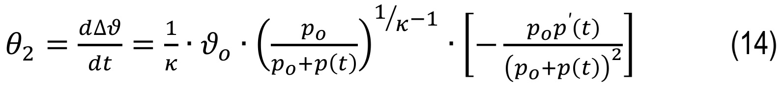
Because in reality air flow is restricted by the interaction between the manifold and the flow-restricting plate with the hole, the change (increase) in pressure inside the absorbers can be expressed as:

where p₀ is the atmospheric pressure, initial inside the LDPE pneumatic absorber, ϑ is the volume of the pneumatic absorber, and κ is the adiabatic exponent, which for air at a temperature of 20ºC takes the value 1.40.
By transforming:
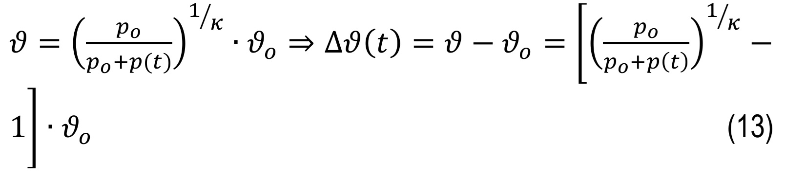
The instantaneous volume of the outflowing air can be determined as a function of time.
The decrease in instantaneous mass flow caused by the attenuation of the opening in the plate can be expressed as follows:
Therefore, the total volumetric flow of air will be the sum of the flow rate of air at its free flow θ1 and the flow rate of air passing through the opening in the collector plate:

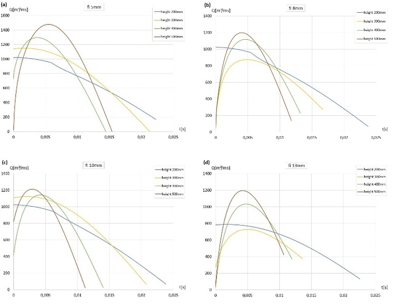
Fig. 21. Air flow rate of five LDPE pneumatic absorbers as a function of time for impactor drop height: 0.2 m, 0.3 m, 0.4 m, and 0.5 m for (a) hole fi 5 mm, (b) hole fi 8 mm, (c) hole fi 10 mm, and (d) hole fi 13 mm
The flow rate characteristics reflect the instantaneous dynamic load of the pneumatic absorber. The characteristics obtained can serve as a basis for further consideration of a technical solution for an air release valve that adjusts air flow to current load conditions.
DISCUSSION
The purpose of the study was to conduct a comparative and quantitative evaluation of the effectiveness of the tested LDPE pneumatic absorbers and EPS100 polystyrene shock absorbers, which are commonly used as padding in motorcycle helmets. During the experimental tests, a drop tower was used, while displacements as a function of time were recorded with a Chronos 2.1HD camera, designed to observe rapidly changing phenomena. The raw results obtained from the experimental tests were approximated in the progressive displacement range using a three-parameter family of sine functions, which were modified to reflect the analytical characteristics by selecting parameters that control the amplitude, period, and convexity of the curve. The degressive range of displacement was described analytically, depending on the needs, using a linear or sinusoidal function, whose parameters were selected appropriately to the experimental data. The approximations of the experimental results obtained accurately reflect the experimental displacement data. The proposed modifications to the sine function are therefore an effective tool for processing experimental data. Furthermore, the obtained analytical mappings are differentiable functions with well-defined derivatives in the considered interval of real numbers. It is also worth mentioning the imperfections adopted by the approximation methodology, which, despite its advantages, is not an ideal solution, which translates into the results of the derived characteristics obtained, that is, errors in estimating speed, acceleration, and dependent indicators. Acceleration characteristics estimated based on the proposed approximation functions are not suitable for calculating the intensity of their changes, known as ‘jerk’. Knowledge of the characteristics of ‘jerk’ would be a valuable addition to research on energy-absorbing elements against the effects of impacts, particularly in the field of human protection. Obtaining ‘jerk’ characteristics requires the use of professional measuring equipment with high-class acceleration sensors and discrete signal filters. More research is planned using high-class acceleration sensors and filtration of acquired measurement data [26-28]. Probably a hybrid method, i.e. optical-digital, using high-speed cameras, acceleration sensors, data filtering procedures, and data approximation can be an effective research tool, enabling the control of results obtained from high-speed cameras and acceleration sensors. As a supplementary element that can also improve the effectiveness of the testing method, an impact force sensor can be used, for example. At the current stage of research presented in this paper, several mechanical characteristics are presented that allow energy absorbers to be evaluated from various perspectives. When LDPE pneumatic absorbers are tested in the tested cases, taking into account the values and acceleration curves, absorbers equipped with an opening are characterised by a visible difference in their favour compared to hermetically sealed pneumatic absorbers. Furthermore, the estimated acceleration curves for LDPE pneumatic absorbers with air flowing through an opening of a specific diameter are more favourable and lower than those for sealed pneumatic absorbers and EPS100 polystyrene absorbers. The cases of absorber types indicate that the most advantageous option is a pneumatic LDPE absorber with a 5mm diameter hole. Furthermore, further reduction of the hole diameter and precise testing seem to be the right direction for further consideration.
CONCLUSIONS
Experimental investigations were carried out on LDPE pneumatic absorbers and EPS100 polystyrene absorbers using a drop tower test stand to enable a quantitative comparison of their dynamic responses. The drop-tower methodology proved to be an effective and versatile tool for the assessment of rapidly changing impact phenomena.
The recorded displacement–time characteristics were approximated using a modified sine function, which allowed the derivation of comparative indicators for the tested absorbers. Although certain imperfections in the approximation were identified, the proposed analytical representation was found to be a practical and effective tool for the analysis of experimental data obtained from dynamic impact tests.
The study highlighted the inherent difficulties associated with the investigation of highly dynamic processes. The results indicate that further improvements may be achieved through a hybrid research approach combining high-speed imaging, acceleration, and force measurements, and appropriate signal filtering, particularly in critical time intervals.
The results confirm that pneumatic absorbers are characterised by high versatility, low cost, and good effectiveness, including under repeated impact loading. A distinct advantage of LDPE pneumatic absorbers over EPS100 polystyrene absorbers is the ability to adapt their mechanical characteristics to specific impact conditions by controlling air flow. Experimental tests performed with plates of defined hole diameters demonstrated the effectiveness of this solution and allowed the estimation of stiffness and damping characteristics for configurations intermediate between sealed and fully open systems.
Finally, knowledge of the dependence of the mechanical characteristics of pneumatic absorbers on air flow creates a basis for the further development of this type of energy-absorbing device, particularly in relation to adaptive control of the flow rate under varying impact conditions.