INTRODUCTION
Magnesium alloys are a group of materials with a wide range of applications. This is primarily due to their low density – the lowest among metals. This is the main feature that makes them a favourable solution where it is crucial to manufacture components with the lowest possible weight. They are therefore widely used in the automotive and aerospace industries, as well as increasingly in the sports and electronics industries. Modern magnesium alloys are also characterised by good corrosion resistance and vibration damping properties. Despite their excellent machinability, their machining is associated with one serious difficulty – the possibility of self-ignition. This is the main characteristic of magnesium alloys that prevents many manufacturers from using them. The ignition temperature depends on the chemical composition, but is usually above 450 °C [1,2]. The possibility of ignition applies particularly to magnesium dust, therefore abrasive processing of magnesium alloys should be avoided. This is a significant limitation in terms of improving the quality of manufactured components. An alternative method therefore seems to be precision machining, the main result of which is high surface quality.
The main feature of precision machining is the very small undeformed chip thickness that is removed during the process. Nevertheless, its values cannot be too low, as this will prevent the initiation of the shearing process and, as a consequence, the material ploughing phenomenon will occur. It results from plastic and elastic deformation of the material, which mainly manifests itself in the deterioration of the surface condition. Burrs are also formed from the deformed material, which require additional operations to remove them. An unfavourable consequence of material ploughing may also be an increase in cutting force, vibrations or stresses [3,4]. Improper implementation of the material removal process may not provide the expected benefits of precision milling, and may even provide negative results. It is therefore important to recognise the ploughing dominant zone, so that undesirable outcomes can be avoided. This requires conducting research into the material removal process, for example using cameras and vision systems. However, in the case of milling, this is considerably more challenging due to the rotating cutting tool and limited visibility of the cutting zone, as confirmed in [5]. The authors conducted up and down milling of C45 steel. The use of a high-speed camera enabled the observation of chip formation, although visibility was limited. Nevertheless, it was observed that the chip shape depended on the milling direction. The up and down milling process was also described in [6], but in relation to the Ti-6Al-4V titanium alloy. By using a high-speed camera, observations of the chip flow direction were taken, which during up milling, was opposite to the direction of tool rotation. This resulted in a higher tendency for chip adhesion to the surface, leading to a poorer surface quality compared to that achieved through down milling. Azmi et al. [7] employed high-speed camera when milling GFRP. The study revealed that chip formation mechanisms in the tested material differ significantly from those observed in conventional materials, showing a higher level of complexity. Machining performed along the direction of the fibres enabled effective chip generation. However, when the cutting was done perpendicular to the fibres (at 90°), the material tended to disintegrate into fine dust rather than form distinct chips. Furthermore, signs of delamination were also detected during the machining process. In turn, high-speed camera was used for observation of deflection of thin-walled components in paper [8]. For comparison, measurements were also conducted using laser sensors. The difference in the results ranged from 11% to 28%, with the error increasing as the wall thickness decreased. As can be seen, the number of articles related to the observation of the milling process is relatively limited.
A high-speed camera was also used for turning of magnesium-based metal matrix composites [9]. Imaging techniques enabled the monitoring of chip morphology as machining parameters varied. At low cutting speeds, the chips exhibited a saw-toothed form, whereas increasing the cutting speed resulted in the formation of particle-type chips. In contrast, other machining parameters had a negligible effect on the resulting chip geometry. Images recorded using high-speed cameras can also be utilized for the evaluation of chip geometry parameters [10]. An increase in cutting speed was primarily associated with a larger shear angle and a decrease in the chip compression ratio. Conversely, a rise in the uncut chip thickness negatively affected both parameters, resulting in a lower compression ratio and a simultaneous increase in the shear angle. Davis et al. [11] examined the orthogonal turning process of commercially pure grade 4 titanium. The study found that at lower cutting speeds, chip formation occurred in a cyclic manner, characterized by periodic segmentation. However, when higher cutting speeds were applied, chip formation became more continuous, and the distance between successive shear bands increased noticeably. In the paper [12], orthogonal cutting of titanium alloy was analysed with particular emphasis on real-time measurement of kinematic fields. The cutting process was monitored using a high-speed camera. The findings indicated that increasing the cutting speed promoted a more uniform shear mechanism and resulted in a reduction of the primary shear zone. The image-based algorithm has been implemented to quantify strain and strain rate from the recorded sequences. It was observed that higher cutting speeds generated slightly lower strain values, while the associated strain rates increased significantly – by several times. The research presented in [13] investigated orthogonal cutting of potassium dihydrogen phosphate, focusing on material removal mechanisms across a broad spectrum of uncut chip thickness. Three separate cutting modes and associated chip geometries were classified based on the variation in cutting depth. During cutting with low uncut chip thickness, only a slight built-up edge was observed. As the undeformed chip thickness increased, chip formation transitioned from continuous flow to the development of chip curling. In [14], the material removal behaviour during orthogonal cutting of cortical bone was investigated, with high-speed microscopy employed to capture the chip formation process. Regardless of the cutting depth, the chips consistently exhibited a serrated structure. Notably, increasing the cutting speed did not alter the shear plane geometry but resulted in narrower chip segments. This refinement in chip morphology was associated with a reduction in the energy required for the cutting process. The research described in the paper [15] used high-speed imaging to analyse orthogonal cutting behaviour in hybrid materials – SAE1020 and SAE5140 steels. The investigation addressed the influence of cutting speed variation, uncut chip thickness, and edge radius on the cutting process. The findings revealed that these factors substantially influenced both the resulting chip thickness and the shear angle. Additionally, the machining parameters had a notable effect on surface quality and cutting forces. When the uncut chip thickness was too low, a transition from continuous to segmented chip formation was observed. The orthogonal cutting behaviour of commercially pure titanium grade 2 was examined in [16], with microstructural analysis performed using a scanning electron microscope. The study focused on the influence of undeformed chip thickness and cutting edge geometry on chips formation. For larger undeformed chip thicknesses values, chip segmentation occurred independently of the tool’s edge geometry. In contrast, when the thickness was reduced, continuous chip formation was observed only in combination with a sharp cutting edge. The application of such a sharp-edge tool not only promoted thicker chips formation but also contributed to improved surface finish and lower cutting forces. The paper [17] examined the influence of cutting coolants on chip formation during orthogonal cutting of AISI 4140. The application of coolant resulted in a noticeable reduction in both, the tool–chip contact length and chip curl. These effects became more pronounced as the coolant pressure was increased. This trend was consistent for cutting tools featuring either a ground or polished rake face. Additionally, application of the coolant contributed to a decrease of cutting forces. Study [18] concentrated on the observation of the orthogonal cutting process of the Ti-6Al-4V titanium alloy with the use of high-speed camera. The recorded image sequences enabled the measurement of tool-chip contact length and chip thickness. Based on these observations, shear strain values were calculated, revealing a positive correlation with increasing cutting speed. In contrast, variations in feed rate had only a minor influence on the shear strain. In the paper [19] utilized high-speed imaging to capture the chip formation process during orthogonal cutting of C45E4 steel. The observations revealed a progressive development of chips, with curling initiating once the chip reached a critical length. The resulting chips exhibited a jagged morphology. To complement the experimental work, numerical simulations were conducted, showing strong correlation with the experimental results. The chip formation mechanism during orthogonal cutting of 2024-T351 aluminium alloy was examined in [20]. Continuous chips were produced at an low uncut chip thickness value, whereas segmentation became evident when the chip thickness was increased. Chip segmentation was further promoted by low cutting speeds and a low rake angle. The occurrence of segmented chips was intensified by rise of cutting speed. High-speed image analysis also enabled estimation of the shear angle, which was found to range between approx. 30° and 40°. A related investigation [21] demonstrated the applicability of high-speed image analysis for studying dynamic phenomena during cutting processes. As part of the study, an image-based algorithm was proposed for the detection of chatter vibrations, highlighting the potential of visual data in monitoring and diagnosing unstable cutting conditions.
As mentioned before, the temperature in the machining area plays a significant role during magnesium alloys milling. During its execution, ignition and explosions may occur [22], which poses a significant risk. Large amounts of heat can also adversely affect the milling process, including geometrical errors resulting from the thermal expansion of cutting tools and workpiece [23–25] or thermal deformation of the machine tool [26]. Karimi et al. [27] conducted temperature measurements during milling of AZ91C magnesium alloy. It was shown that the temperature increased with increasing cutting speed. Higher temperatures were also achieved when using higher depth of cut. These relationships were recorded using an IR thermometer and thermocouples. Temperature changes during milling of the AM50 alloy [28] were similar, as recorded using thermocouples. In this case, the temperature also increased with increasing cutting speed. The increase was also observed during long machining times. Flares were also observed during machining. A temperature increase due to increased cutting speed was also demonstrated when milling AZ31 alloy [29,30]. Thermal imager also recorded a temperature increase when increasing feed and depth of cut. In turn, Zhang et al. [31] observed a temperature increase only at cutting speeds below 300 m/min. Above this speed, the temperature began to gradually decrease. Magnesium alloys are typically machined in dry conditions, due to the potential for explosions when using water- and oil-based coolants. This significantly reduces the possibility of reducing the temperature in the cutting zone. However, attempts are being made to improve safety through the use of Minimum Quantity Lubrication (MQL) [32,33] and cryogenic cooling [34,35]. In addition to temperature reduction, these methods also improve surface quality and reduce cutting forces [36,37]. However, they require additional equipment to implement them. To date, only a few other studies have been published on micro-milling of magnesium alloys, and these have concentrated mainly on the assessment of surface roughness or cutting force [38–42]. However, none of them concern the analysis of the material cutting process using vision devices and cutting temperature measurements. Furthermore, their number is negligible compared to other materials such as aluminium or titanium alloys. The proposed research topic is therefore poorly explored and requires further research in this area, especially considering the limitations in the machining of magnesium alloys. Nevertheless, due to the increasingly widespread use of magnesium alloys in different industries, the need for research on this group of materials is justified.
The purpose of the study is to analyse the precision milling process of AZ31B and AZ91D magnesium alloys. The observation of the material cutting process is aimed at determining the range of feed per tooth where the material shearing occurs. This will enable the minimisation of material ploughing, which adversely affects the machining process and, above all, on the surface condition. The study also analysed the burrs formation, which are also an undesirable result of machining. The research also included temperature measurements in the cutting zone, which are particularly important in the aspect of safety. The main novelty is the research conducted in the area of material removal process analysis, burr formation, and temperature measurements during precision milling of AZ31B and AZ91D magnesium alloys. Another novelty is the attempt to identify a transition zone between material ploughing and shearing for these materials. As presented in the literature review, this type of research has not been conducted for these magnesium alloys before.
MATERIALS AND METHODS
Investigations into precision milling were conducted on AZ31B (stage I and II) and AZ91D (stage II) magnesium alloys. These are two popular materials from the AZ (Mg-Al-Zn) group. Due to their low density, they are mainly utilised in the aviation and automotive sectors. The mechanical properties of the analysed materials are presented in Table 1.
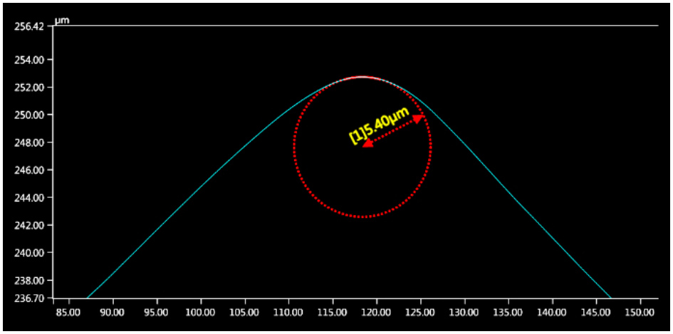
Cuboidal specimens were prepared from these materials and then precision milled on an AVIA VMC 800HS milling centre. A double-flute end mill with a diameter of 16 mm was applied as a cutting tool. This tool is suitable for the milling of light metal alloys and has a helix angle of 45°. The tool is made of fine grain carbide, which allows for greater flute manufacturing accuracy. The tool was not coated with any protective coating. Using a Keyence VHX-5000 digital microscope, measurements of the cutting edge radius rn were taken – Fig. 1. This radius has a similar value to the undeformed chip thickness in precision machining. The determined radius value was rn = 5.4 µm and was used to determine the appropriate feed per tooth range.
The research was divided into two stages and carried out with the cutting parameters presented in Table 2. The machining was performed in dry conditions. In the first stage, research was conducted to observe the material removal process. The aim was to analyse chip formation by cutting flutes depending on the undeformed chip thickness. For this reason, the feed per tooth was selected based on the determined value of the cutting edge radius. The precision milling process was carried out in the range of fz/rn = 0.1–1.0. The aim was to analyse whether material ploughing or material shearing occurs. For this purpose, a Phantom v1610 high-speed camera with a Nikkor AF 80–200 mm f/2.8D lens (Fig. 2) was used for the tests. The process was recorded at a frequency of 10,000 fps. The recordings were analysed and frames presenting the formation of chips by both cutting flutes were extracted.
Tab. 2.
Machining conditions
| Cutting parameter | Stage I | Stage II |
|---|---|---|
| vc (m/min) | 800 | 400 – 1200 |
| fz (µm/tooth) | 0.54 – 5.40 | 0.54 – 5.40 |
| ap (mm) | 0.15 | 0.05 – 0.25 |
The second part of the research focused on measurements of temperature in the cutting zone. First, experiments were conducted for different undeformed chip thicknesses, analogously to the material removal process studies. In the next stage, the experiments were conducted according to a Central Composite Design (CCD) as part of the implementing of Response Surface Methodology (RSM) – Table 3. The results obtained were also subjected to statistical analysis using the ANOVA method. The aim was to assess the impact of machining conditions on the cutting temperature and their interactions. The measurements were carried out using a FLIR x6540sc thermal imaging camera (Fig. 2). Based on the recorded data, the maximum temperature in the cutting tool-workpiece contact area was determined. This is the most significant factor in terms of machining safety. During the measurements, an emissivity coefficients of ɛ = 0.18 (AZ31B) and ε = 0.25 (AZ91D) was used. The emissivity coefficients for the tested materials were determined experimentally in a tube furnace in which the magnesium alloy samples were placed. The samples were heated in the range from 150 °C to 250 °C in steps of 50 °C until thermal equilibrium was reached. The emissivity coefficient was determined by comparing the readings of a thermal imaging camera with the temperature of the samples.
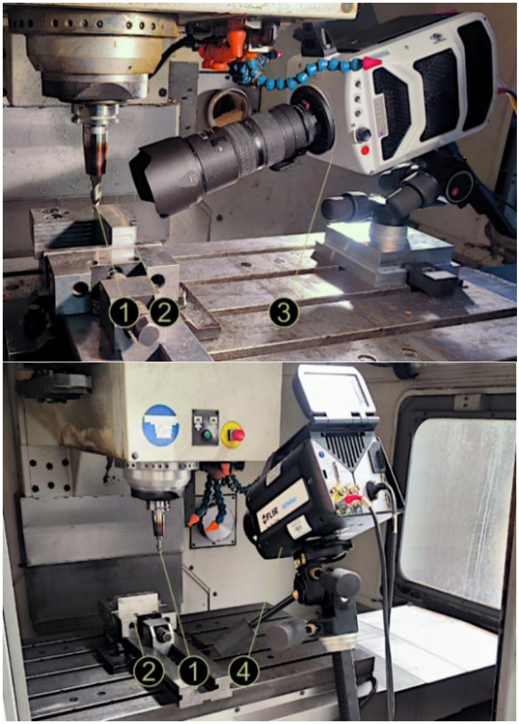
Fig. 2. Research setup (1 – end mill, 2 – workpiece, 3 – high-speed camera, 4 – thermal imaging camera)
Tab. 3.
CCD plan for Stage II
RESULTS AND DISCUSSION
Material removal process
The material removal process analysis was performed based on recordings from which frames showing chips formed by both cutting flutes were extracted. They were subjected to additional graphic processing to improve their quality. Despite this, it was not possible to achieve full sharpness. The main difficulty in milling processes is the rotation of the cutting tool, which has also been confirmed by other researchers [5–7]. The second factor is the very small undeformed chip thickness, which made it difficult to obtain the appropriate magnification of the cutting zone. This required the selection of a lens that would provide the sufficient magnification, but at the same time reduced the depth of field. Therefore, a compromise between magnification and image quality was necessary. Despite this, it was possible to obtain images in which the formed chips are visible – Fig. 3.
The compiled images show chips formed after the cutting flute has completed a full range of movement. The most noticeable difference was the chip size that was shaped by both cutting flutes. Chips formed by the first flute were significantly larger, and their formation was noticeable right at the beginning of the flute's movement range. This means that the material volume was sufficient to initiate the material shearing process. In contrast, the chips shaped by the second flute were extremely small and barely visible, even when using the highest feed per tooth. It can therefore be concluded that the volume of material removed by the both cutting flutes was uneven. The cause of this phenomenon is the radial run-out of the end mill, resulting in uneven operation of the cutting flutes. This is confirmed by measurements carried out in the paper [45], where experiments under similar conditions were conducted for AZ91D magnesium alloy. Also there, the second flute formed only small chips, and their size decreased as the feed per tooth decreased. As a result of the tool run-out, the trajectory of both cutting flutes is different. One flute is further forward, while the second is retracted. As a result, the volume of material removed by the first flute is greater, which results in the formation of a larger chips. Similar relationships are also observed in this case for the AZ31B magnesium alloy. Also here, a reduction in the feed per tooth resulted in a reduction in chip size, mainly visible in the case of chips formed by the first flute. However, there are also some differences between the machining of these two materials, mainly for the second flute. Considering the AZ91D alloy, chips were formed across the entire feed range, even at the lowest values. In addition, the amount of fine chips at the highest feed was greater than for the AZ31B. In turn, during precision milling of the AZ31B, the chips at the lowest feed per tooth were almost invisible and became more clearly visible only from fz/rn = 0.3. This indicates that this material is more susceptible to ploughing, which results from its greater plasticity. As a result, the material deformed more, which made it difficult to initiate the shearing process, and it only began at higher feed per tooth than for the AZ91D. Apart from that, no major differences were observed between the machining of these two materials. However, there are currently no other studies on the observation of chip formation during precision machining of magnesium alloys with which the obtained results could be compared.
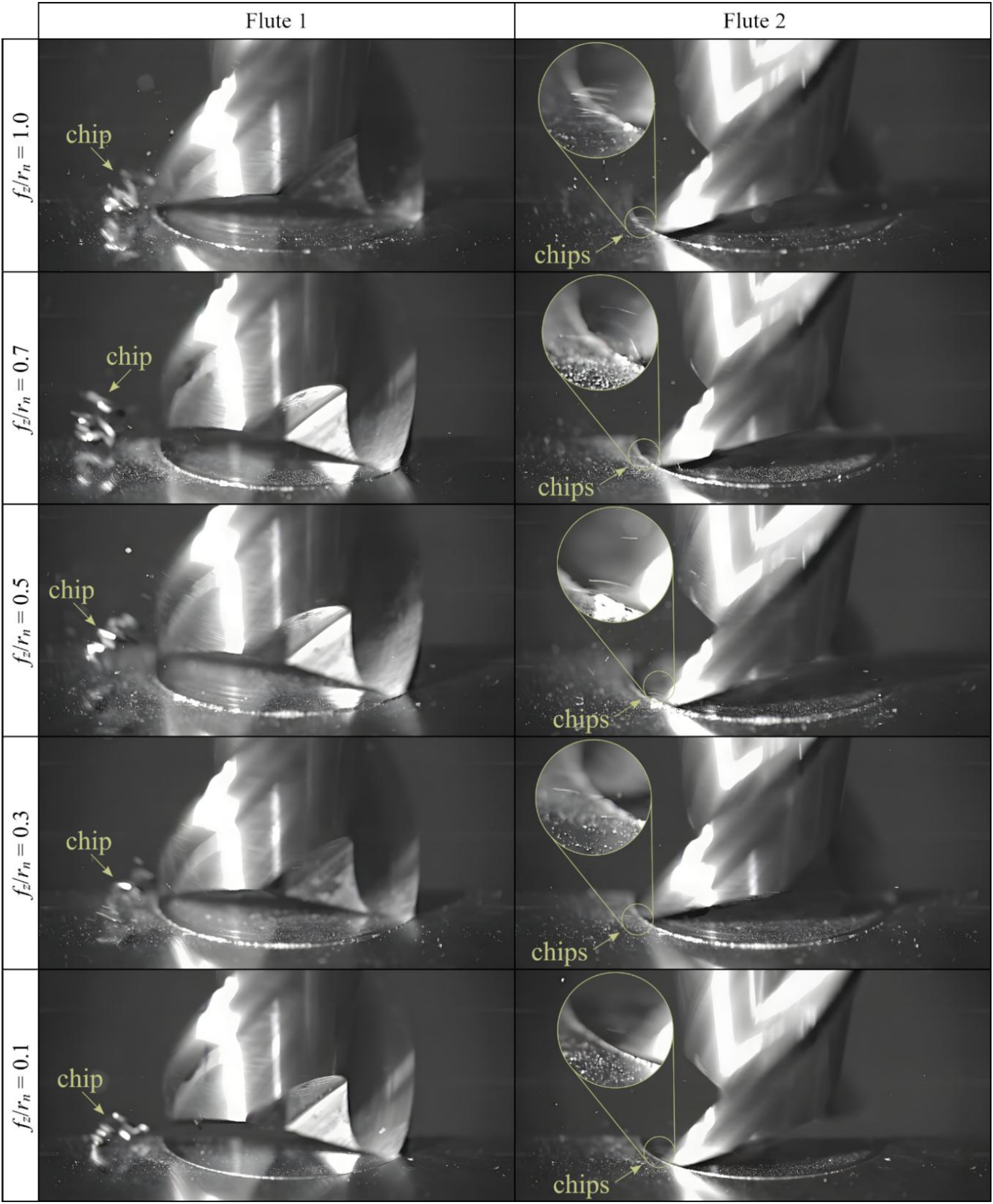
The compiled images show chips formed after the cutting flute has completed a full range of movement. The most noticeable difference was the chip size that was shaped by both cutting flutes. Chips formed by the first flute were significantly larger, and their formation was noticeable right at the beginning of the flute's movement range. This means that the material volume was sufficient to initiate the material shearing process. In contrast, the chips shaped by the second flute were extremely small and barely visible, even when using the highest feed per tooth. It can therefore be concluded that the volume of material removed by the both cutting flutes was uneven. The cause of this phenomenon is the radial run-out of the end mill, resulting in uneven operation of the cutting flutes. This is confirmed by measurements carried out in the paper [45], where experiments under similar conditions were conducted for AZ91D magnesium alloy. Also there, the second flute formed only small chips, and their size decreased as the feed per tooth decreased. As a result of the tool run-out, the trajectory of both cutting flutes is different. One flute is further forward, while the second is retracted. As a result, the volume of material removed by the first flute is greater, which results in the formation of a larger chips.
Similar relationships are also observed in this case for the AZ31B magnesium alloy. Also here, a reduction in the feed per tooth resulted in a reduction in chip size, mainly visible in the case of chips formed by the first flute. However, there are also some differences between the machining of these two materials, mainly for the second flute. Considering the AZ91D alloy, chips were formed across the entire feed range, even at the lowest values. In addition, the amount of fine chips at the highest feed was greater than for the AZ31B. In turn, during precision milling of the AZ31B, the chips at the lowest feed per tooth were almost invisible and became more clearly visible only from fz/rn = 0.3. This indicates that this material is more susceptible to ploughing, which results from its greater plasticity. As a result, the material deformed more, which made it difficult to initiate the shearing process, and it only began at higher feed per tooth than for the AZ91D. Apart from that, no major differences were observed between the machining of these two materials. However, there are currently no other studies on the observation of chip formation during precision machining of magnesium alloys with which the obtained results could be compared.
Burrs
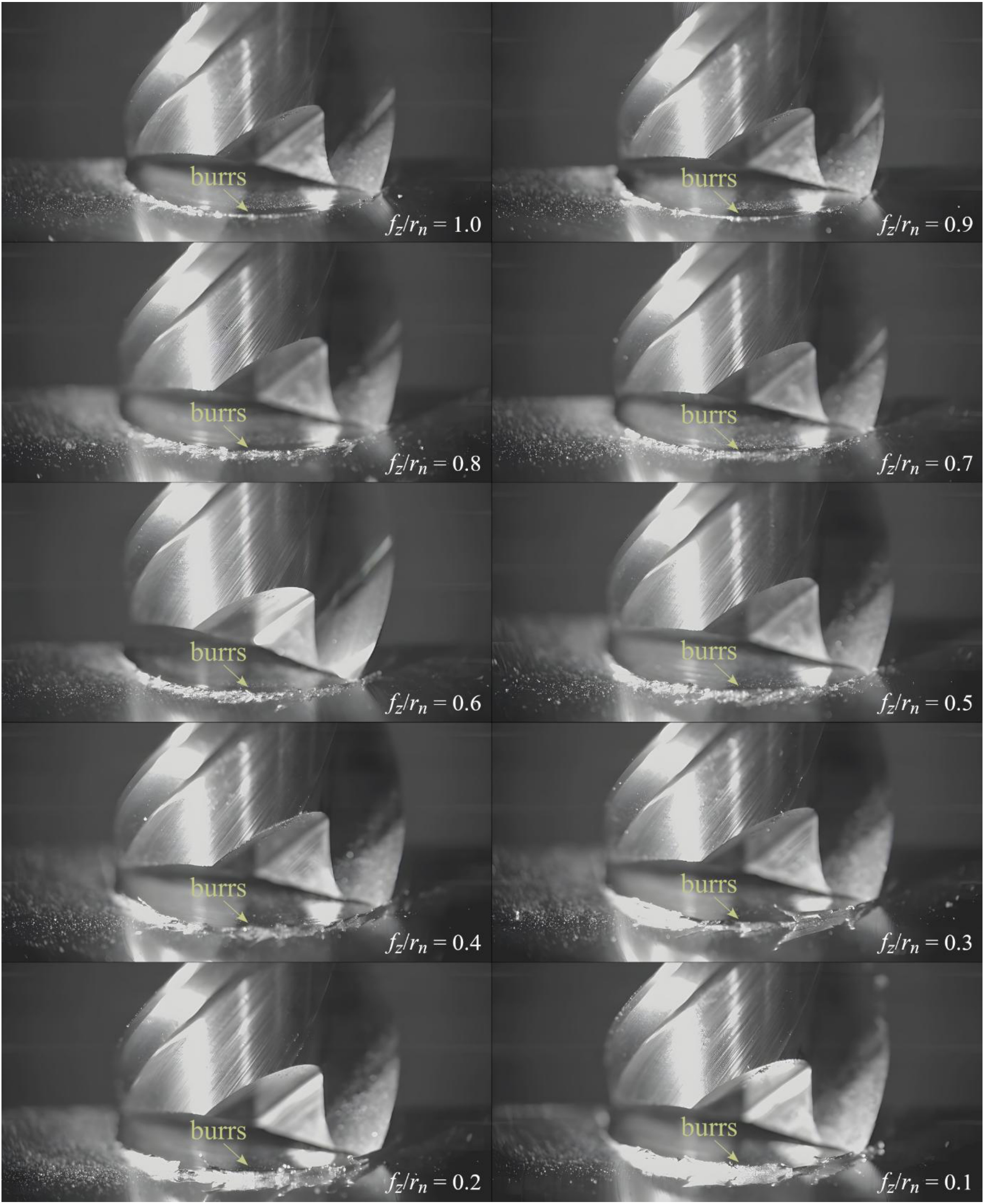
During observation of the material removal process, burrs were also observed forming on the edges of the slot – Fig. 4. These are the result of material plastic deformation in the side sectors of the slot, where the undeformed chip thickness is smallest, which further promotes their formation.
The smallest burrs appeared when the highest feed values were used in the range of approx. fz/rn = 0.9–1.0. As a result, the undeformed chip thickness was greater, which meant that less material underwent plastic deformation and consequently turned into burrs. As the feed per tooth decreased, the size of the burrs increased. This is due to the decreasing undeformed chip thickness, which resulted in a larger volume of material undergoing plastic deformation. The smaller the undeformed chip thickness and the greater the contribution of ploughing, the larger the burrs become.
This is further confirmation that efforts should be made to minimise the material ploughing. When analysing the AZ91D alloy [45], the size of burrs also increased as the feed per tooth decreased. However, the largest burrs occurred in the side sectors of the slot, and the burrs were more branched. In the case of the AZ31B alloy, burrs formed along the entire edge, and at low feed range of approx. fz/rn= 0.1–0.3, they had a more compact surface form.
Cutting temperature
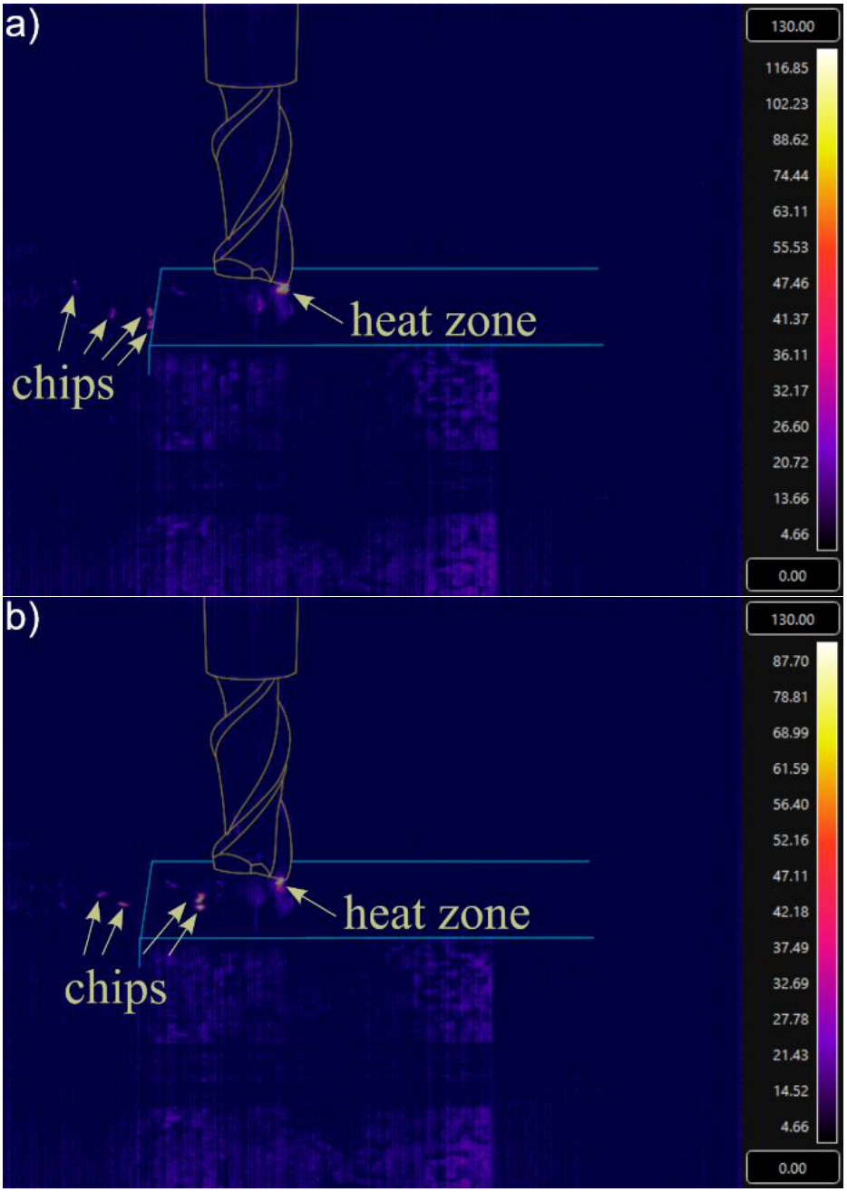
The second part of the study focused on measuring the temperature reached in the cutting zone – Fig. 5. The recordings show that the highest temperature was generated at the tool-workpiece interface. This is a result of the cutting, material deformation and friction occurring in this zone. It can also be observed that the heat zone generated by the first flute was larger, which is consistent with material removal process observations. The greater volume of material removed by this flute resulted in greater heat generation. As a result of the heating, chips were also clearly visible, but their temperature was lower than in the contact zone.
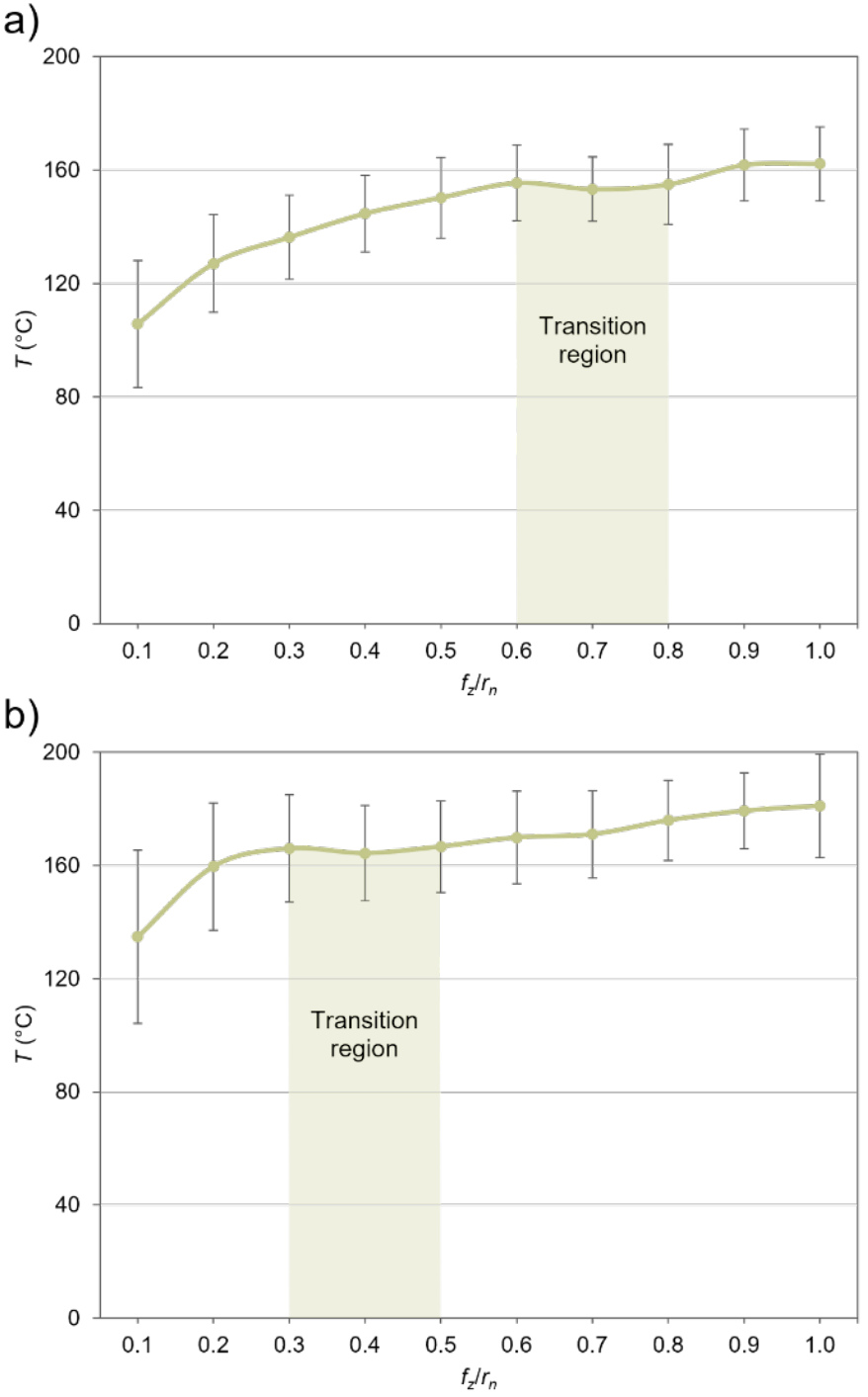
First, measurements were taken for different undeformed chip thicknesses – Fig. 6. For both magnesium alloys, it was observed that the lowest maximum temperature occurred when the lowest feed per tooth was applied. Under these conditions, there was also the greatest variation in values, indicating large fluctuations in temperature. This is due to the varying volume of material removed as a result of material ploughing. When the volume of material was too small to initiate the shearing process, the temperature was lower. However, when the material accumulated and was removed, the generated temperature was higher. As the feed per tooth increased, there was a gradual increase in cutting temperature, resulting from the increasing volume of material removed. At the same time, the dispersion of values also decreased, indicating greater temperature stability. For AZ31B alloy, the temperature increased up to fz/rn = 0.6–0.8, where it stabilised. This region can be considered a transition zone between the ploughing and shearing dominant zones. Further increases in the feed per tooth resulted in a subsequent increase in the maximum temperature. The situation was similar during precision milling of the AZ91D alloy, but in this case, the temperature remained stable in the range fz/rn = 0.3–0.5, so the transition zone occurred for lower values. However, increasing the feed per tooth in the shearing dominant zone caused the temperature to increase again. The maximum temperatures generated during machining of both alloys were quite similar, but the temperature was approx. 20–30 °C lower for the AZ31B alloy. This is probably due to the lower hardness of this material. Although lower temperatures can be achieved using a low feed values, its use is not recommended due to the risk of material ploughing. To maintain the correct course of the material removal process, it is necessary to use a higher feed rate per tooth. Despite achieving maximum temperatures that are approx. 50–60 °C higher, these values are well below the assumed ignition limit.
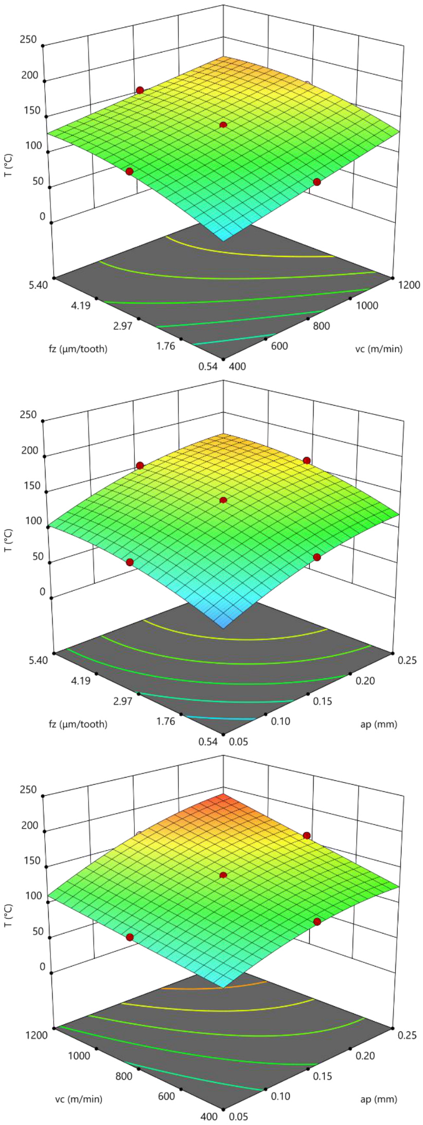
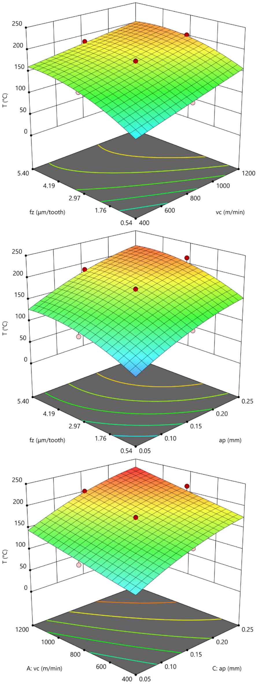
In the next stage, a precision milling process was carried out under variable machining conditions, in accordance with the design of experiment based on the RSM method. The influence of cutting parameters on the maximum temperature is presented in the form of spatial graphs in Figs. 7–8. Similarly to the results presented in Fig. 6, the lowest maximum temperature was obtained using the lowest feed values. However, along with the increase in feed per tooth, the temperature also increased. The reduction in cutting temperature was also facilitated by the reduction in axial depth of cut, due to the removal of smaller material volume. The temperature also decreased approximately linearly when the cutting speed was reduced. Therefore, the most advantageous in terms of cutting temperature is to use the lowest possible cutting parameters. This applies to both magnesium alloys. At this point, it is not possible to compare the obtained results with others, as the available publications concerned conventional machining [27–31]. Furthermore, they were carried out under completely different conditions (type of tool, parameters, alloy), which has a decisive impact on the temperature value. Despite these differences, the trend of temperature increase as a result of increased machining parameters is consistent.
The observed relationships were also confirmed by statistical analysis – Tables 4–5. ANOVA revealed that all cutting parameters significantly affect the maximum temperature. The greatest impact of approx. 42% and 50%, was exerted by the axial depth of cut, which indicates that the volume of material removed significantly contributed to the amount of heat generated. The impact of the other cutting parameters was nearly half as large. The effect of cutting speed was approx. 27% for the AZ31B alloy and approx. 21% for the AZ91D alloy. However, the influence of feed per tooth in the case of machining both materials was approx. 24%. Furthermore, the quadratic effects fz2 and ap2 indicates that they have a non-linear effect on the maximum temperature. In addition, there is an interaction between cutting speed and feed per tooth. For AZ31B alloy, there is also an interaction between the cutting speed and the axial depth of cut. In general, the developed models fit very well, which is also confirmed by a low residual of only approx. 0.5% and 1.6%.
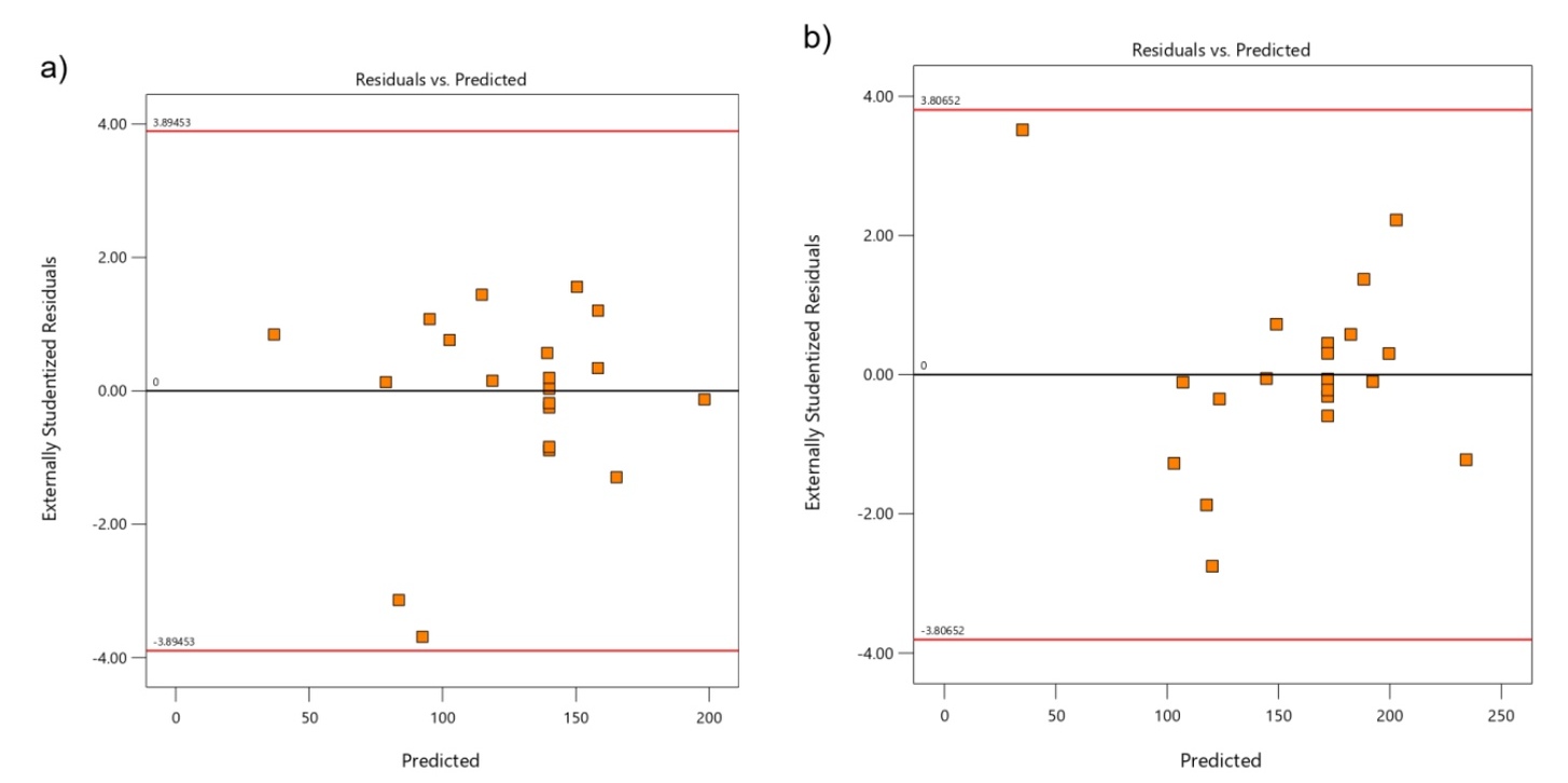
Residual diagnostics based on plots of externally studentized residuals (Fig. 9) indicated a random scatter of values around zero with no discernible systematic patterns. The spread of residuals appeared approximately constant across the range of predicted values, and no observations exceeded the critical limits, indicating the absence of influential outliers, even though the single values are close to the limits. Comparable patterns observed across diagnostic plots suggest that the assumptions underlying the ANOVA model were not violated, so there is no basis for suggesting that the model is poorly fitted.
Tab. 4.
ANOVA for cutting temperature of AZ31B
Tab. 5.
ANOVA for cutting temperature of AZ91D
Regression equations were also determined for the obtained results, respectively for the AZ31B and AZ91D alloys:


The high values of the coefficient of determination R² = 0.9955 and R² = 0.9838 indicate that the models fit the experimental results very well.
CONCLUSIONS
The research provided valuable insights into the precision milling of magnesium alloys. Following these findings, the following conclusions were drawn:
The chips size that was formed by both cutting flutes differed significantly as a result of uneven cutting tool operation caused by its radial run-out. To maintain the correct course of the material removal process, it is therefore necessary to minimise this adverse phenomenon. Furthermore, in the lower feed per tooth range, material ploughing occurs.
During precision milling, burr formation was observed, and their size decreased as the feed value was reduced. The decreasing undeformed chip thickness therefore promoted their occurrence.
The maximum cutting temperature increases gradually with increasing undeformed chip thickness. Although the lowest temperatures are achieved when using a low feed per tooth values, this is not favourable due to the simultaneous occurrence of material ploughing. The transition zone for the AZ31B alloy was approx. fz/rn = 0.6–0.8, and for the AZ91D alloy approx. fz/rn = 0.3–0.5.
All cutting parameters have a significant effect on the maximum temperature, and there are also interactions between them. The greatest effect (over 40%) is exerted by the axial depth of cut, while the effect of the other parameters was over 20%. The use of low machining parameters helps to reduce the cutting temperature.
Precision milling of AZ31B and AZ91D magnesium alloys can be performed safely using carbide end mill, as the maximum cutting temperatures achieved are well below the ignition temperature. This method therefore increases the safety of magnesium alloy machining.