INTRODUCTION
Functionally graded piezoelectric materials (FGPMs) represent a modern class of piezoelectric composites in which the electro‑elastic characteristics vary continuously along the thickness direction. Numerous studies have focused on the mechanical and vibrational responses of both piezoelectric and functionally graded structural elements. For instance, Liew et al. [1] developed a finite‑element framework for piezo‑thermoelastic analysis of functionally graded plates equipped with embedded piezoelectric sensor and actuator layers. Their work examined bending and torsional vibration control of FG plates exposed to thermal gradients by employing self‑sensing actuators. Zhao et al. [2] explored the free vibration behavior of functionally graded plates using the element‑free kp‑Ritz technique, demonstrating that the volume‑fraction exponent plays a crucial role in determining natural frequencies. Behjat and Khoshravan [3] investigated nonlinear static bending and free vibration responses of FGPM plates, concluding that for all values of the volume‑fraction index "n", the deflection of the plate increases noticeably under mechanical loading. Farsangi and Saidi [4] provided an exact analytical formulation for the vibration of rectangular FG plates with surface‑bonded piezoelectric layers, showing that increasing the thickness‑to‑length ratio enhances the natural frequencies across mechanical and electrical boundary conditions. Komijani et al. [5] reported that the mechanical behavior of unsymmetrical piezoelectric beams differs fundamentally from that of symmetrical configurations. Lezgy et al. [6] introduced a conforming three‑noded beam element capable of predicting the static, modal, and transient responses of FGM beams. Sharma and Kumar [7] examined the flexural vibration characteristics of short‑circuited FGPM annular plates subjected to shear‑induced excitation, and their analytical formulation showed strong agreement with numerical results obtained from COMSOL simulations. Their study indicated that the natural frequencies rise as the thickness‑to‑diameter ratio increases, and also grow with the volume‑fraction index up to a value of 5. Selim et al. [8] proposed an efficient methodology combining Reddy’s higher‑order shear deformation theory (HSDT) with the element‑free IMLS‑Ritz scheme to analyze free vibration and active vibration suppression of FGPM plates incorporating piezoelectric layers. Their findings revealed that plates with open‑circuit piezoelectric layers consistently exhibit higher natural frequencies than those with closed‑circuit electrical conditions due to electromechanical coupling effects. Nourmohammadi and Behjat [9] explored the bending response of FGPM plates under mechanical, electrical, and thermal loading using the first‑order shear deformation theory (FSDT), showing that the relationship between deflection and the volume‑fraction index varies depending on the type of applied load. Mikaeeli and Behjat [10] introduced a three‑dimensional Element‑Free Galerkin (EFG) formulation to study the static behavior of thick FGPM rectangular plates with arbitrary gradation profiles, applying it to model multi‑field piezoelectric and non‑homogeneous problems. Lezgy et al. [11] investigated the use of FGPMs in passive vibration damping of laminated composite beams, demonstrating that the R–L shunt circuit provides the most effective damping performance regardless of the material gradient. Nguyen‑Quang et al. [12] extended the CS‑DSG3 technique employing three‑node triangular elements to perform static analysis, free vibration assessment, and dynamic control of FGM plates integrated with piezoelectric sensors and actuators. Their results confirmed that the CS‑DSG3 approach relies solely on simple three‑node linear triangular elements, making it highly suitable for automatic mesh generation in complex geometrical domains. Ruocco and Mallardo [13] formulated a new finite strip model combined with the Kantorovich method to study the buckling and vibrational behavior of imperfect nanoplates. Thang et al. [14] explored the bending and buckling responses of bidirectional functionally graded composite nanobeams, whereas Tang and Dai [15] examined the stability behavior of laminated piezoelectric cylindrical shells subjected to various environmental influences. Fan et al. [16]–[19] employed the isogeometric analysis framework to model microscale plates of different geometries incorporating FG porosity and size‑dependent characteristics. Rahimi et al. [20] provided analytical predictions for the free vibration and bending performance of FGP‑GPLRC cylindrical shells, while Ton‑That et al. [21] assessed the bending, vibrational, and buckling behavior of FGP‑GPLRC plates. Wang and Liu [22] introduced piezoelectric composite materials (PCMs) consisting of a substrate combined with piezoelectric layers to illustrate the active elastic behavior of composite systems, showing that their elastic properties are influenced by geometry, constituent materials, and applied voltage. Tran et al. [23] studied the free vibration characteristics of piezoelectric FGP‑GPLRC plates under different boundary conditions, demonstrating that incorporating a lightweight metal‑foam core together with graphene platelets enhances stiffness and provides an efficient configuration for sandwich plates. Alshenawy et al. [24] formulated a three‑dimensional strain‑gradient shell model to analyze the micro‑scale‑dependent nonlinear stability of FG piezoelectric micro‑shells under thermo‑electromechanical loading, revealing that the inclusion of microstructural strain‑gradient tensors increases the critical mechanical and electrical loads associated with buckling. Bastami and Behjat [25] investigated the buckling and free vibration behavior of piezoelectric nanoplates resting on an elastic foundation using Kirchhoff plate theory, concluding that both the critical buckling load and the natural frequency decrease as the nonlocal parameter increases. Kumar et al. [26] examine the stress response, deformation characteristics, and vibrational performance of porous functionally graded piezoelectric tapered plates subjected to thermoelectric and mechanical loads by employing advanced finite element. Their findings are offering guidance for the development of smart structural components and biomedical sensing devices. In another study, the authors conduct a free vibration investigation of porous functionally graded plates using three‑dimensional degenerated shell elements formulated on Reissner–Mindlin theory, achieving lower computational cost while still accurately representing the variation of material properties through the thickness [27]. Kumar and Harsha [28] propose a higher‑order finite element formulation based on first‑order shear deformation theory to evaluate the hygrothermal static behavior of nanoscale, multidirectional nanofunctionally graded piezoelectric (NFGP) plates supported by spatially varying elastic foundations. In a related work, the bending response, deflection pattern, and vibrational characteristics of porous multidirectional functionally graded circular piezoelectric plates resting on variable elastic foundations under thermo‑electro‑mechanical loading are analyzed. The study reveals that the porosity level has a pronounced effect on static deflection, radial stress distribution, and the natural frequencies [29]. Kumar et al. [30] explore the buckling performance of porous PZT‑4/PZT‑5H smart graded plates supported by Winkler–Pasternak foundations when exposed to combined thermomechanical and thermoelectric loadings. Another investigation addresses the static and dynamic responses of exponential functionally graded piezoelectric materials under thermo‑electro‑mechanical effects using first‑order shear deformation theory (FSDT) and Hamilton’s principle [31]. The nonlinear vibration characteristics of porous multidirectional piezoelectric functionally graded nonuniform plates placed on orthotropic variable elastic foundations and subjected to hygrothermal environments are studied by Kumar et al. [32]. Free vibration analyses of porous functionally graded material (FGM) sandwich plates in thermal fields are also performed [33]. Two configurations—sandwich plates with FGM face sheets and homogeneous cores, and those with homogeneous face sheets and FGM cores—are considered, incorporating nonlinear temperature variation across the thickness for the vibration assessment. Harsha et al. [34] examine the thermoelectric vibration and buckling characteristics of a bidirectional functionally graded piezoelectric porous plate supported by an elastic foundation and subjected to general boundary conditions. Their work analyzes the dynamic behavior of functionally graded piezoelectric plates through a finite element framework and proposes an innovative multilayer configuration. The study evaluates the structural response under combined mechanical and electrical loading scenarios while considering variations in boundary constraints. Particular attention is given to how geometric configuration, gradation profiles, and power‑law indices influence system performance. The accuracy of the formulation is demonstrated through comparison with previously published results. The findings highlight the significant impact of material distribution, plate thickness, and aspect ratio on the dynamic response, offering valuable guidance for the design of structures used in aerospace systems, vibration mitigation, and energy‑harvesting technologies.
Novelty statement: This research develops a new multilayer model for functionally graded piezoelectric plates and explores their dynamic behavior under simultaneous mechanical and electrical excitations. By assessing the influence of structural configuration, boundary conditions, multiple piezoelectric layers, and power‑law gradation parameters, the study provides fresh insights that can enhance the design and optimization of FGPM‑based components for advanced engineering applications.
METHODS
Functionally graded piezoelectric plates
A variety of models have been presented in order to simulate the material distribution throughout the thickness of the plate. However, power law distribution is commonly used to simulate the material properties distribution. For FGM structures made of two different materials, material "a" in the top surface and material "b" in the bottom surface of the plate, the effective properties of the FGPM profile in the thickness direction of the plate can be written as [9]

where "Peff" is the effective material property of the FGPM plate, "Pa" is the upper surface property of the FGPM plate, "Pb" is the lower surface property of the FGPM plate, and "Va" is the volume fraction of the functionally graded piezoelectric upper material. Finally, the material properties can be expressed as:

where "z" shows the distance from the neutral axis of the plate and “h” represents the plate thickness. In this article, all of the material properties differ throughout the thickness by following the simple power law distribution (2.2) excluding Possion's ratio. The simple power-law model is widely adopted in functionally graded materials due to its mathematical simplicity and ease of implementation in finite element formulations. It offers flexibility by adjusting the exponent to represent different gradation profiles and ensures computational efficiency, making it a standard choice for analysis and comparison in FGM research.
Theoretical formulations
Displacements and Strain Relations
According to the FSDT, the displacement field in the plate can be expressed as [35]:
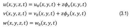
where the variables u, v, and w denote displacements along the x,
y, and z axes, respectively. Also, u0, v0, and w0 denote the
displacements of a point in the mid-plane, and
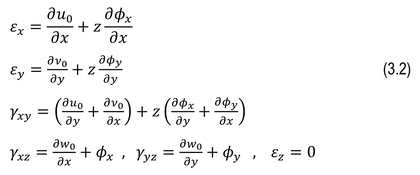
Note that the strains

where

where
Constitutive equations of piezoelectric material
Based on the linear theory of piezoelectricity, the constitutive equation for piezoelectric plate can be written as [22]:

where,
Final equations of motion
The equations of motion for the plate are obtained by applying the extended Hamilton’s principle [37]:

Where
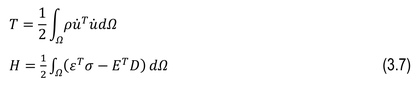
where
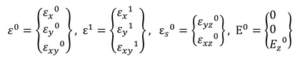
By integrating in thickness direction, and replacing the strain
field and assuming that
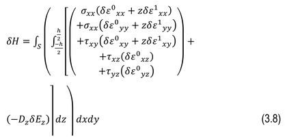
By combining (3.5) and (3.8) the final Equation of electromechanical energy can be written as follow:
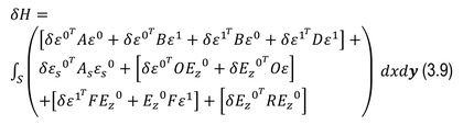
Here O is the coupled tensile stiffness matrix, F demonstrate the coupled tensile-bending stiffness matrix and R is the dielectric tensile stiffness matrix that can be defined as follow:
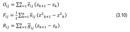
The tensors in (3.10) are defined as:
Kinetic energy in (3.7) using integral by part finally can be written as:

Finite element model
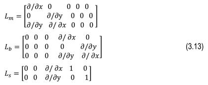
Using (3.2) the strain relation can be written as:

where, [Lm], [Lb], [Ls] are strain operators based on the displacements-strain relations and can be defined as follows:
In (3.6) the work done by external mechanical force and applied electric charge are defined as [38]:

where
The last integration refers to applied electrical charge. By combining (3.9), (3.11) and (3.6) and assume that only concentrated force be applied on the plate. (3.15) can be written in matrix form as follow:

Where submatrices M, u and
The above matrices defined as follow:
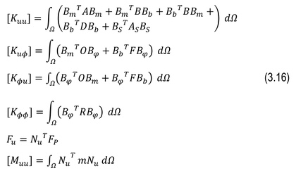
Where the m matrix defined as [39]:
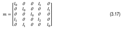
And I can be defined as:

Here
Newmark method
In this article, the Newmark method is used to solve the final time dependent equation of motion. In this method, the acceleration is assumed to vary in a specific manner over each time step. The finite difference relationships for the Newmark-β method are [40]:


where

For linear systems, it is possible to modify Newmark’s original formulations in matrix form as:

RESULTS AND DISCUSSION
Comparison studies
To support the findings of this study, two examples were used to compare the data with results from previous studies by Selim et al. [8] and Nguyen-Quang et al. [12].
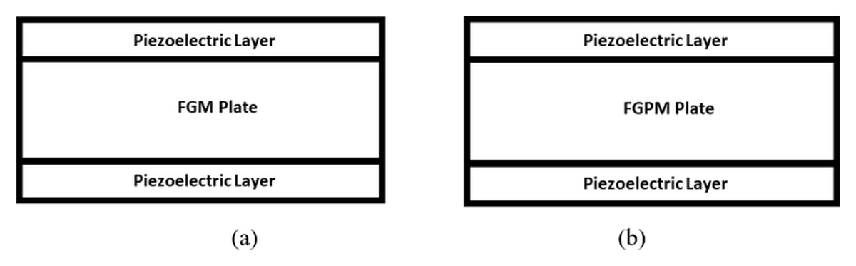
Example 1 focuses on the dynamic response of a plate without the damping effect. The plate analyzed is a CFFF functionally graded material (FGM) plate composed of Aluminum Oxide and Ti–6Al–4V materials at room temperature (300 K), as described by Selim et al. [8]. Two G1195N piezoelectric layers are bonded to the top and bottom surfaces of the FGM plate. In this configuration, the actuator is located on the top surface, while the sensor is placed on the opposite bottom side. This configuration is shown in Fig. 1-a. Also Fig. 1-b describes the functionally graded piezoelectric plate that has other piezoelectric layers in top and bottom as sensor and actuator layers. The second configuration will be addressed in the next example. The plate has dimensions of 0.3 m in both length and width, with a thickness of 5 mm. Each piezoelectric layer has a thickness of 0.1 mm. The material properties are provided in Tables 1 and 2.
Initially, the plate is subjected to a uniformly distributed load of q=100 N/m² in the downward vertical direction. Subsequently, the load is removed, resulting in motion generated from the initial displacements. The tip deflection response of the plate is calculated with a time step of 0.001 s, and the system is solved using a state-space model. Figures 2 and 3 demonstrate a satisfactory agreement between the results obtained in this study and those reported by Selim et al. [8].
Tab. 1
Material properties of G-1195N and PZT-4 [41]
Material | G-1195N | PZT-4 |
ε33 (F/m) | 15e−9 | 1.15e−8 |
e32 (m/V) | 254e−12 | −1.22e−10 |
e31 (m/V) | 254e−12 | −1.22e−10 |
ρ (kg/m3) | 7600 | 7600 |
ν | 0.3 | 0.33 |
E22 (GPa) | 63 | 81.3 |
E11 (GPa) | 63 | 81.3 |
Tab. 2
Material properties of Aluminum Oxide and Ti-6Al-4V [41]
Material | Young’s moduli (GPa) | Poisson’s ratios | Density (kg/m3) |
Ti-6Al-4V | 105.7 | 0.29 | 4429 |
Aluminum oxide | 320.2 | 0.26 | 3750 |
Aluminum | 70 | 0.3 | 2707 |
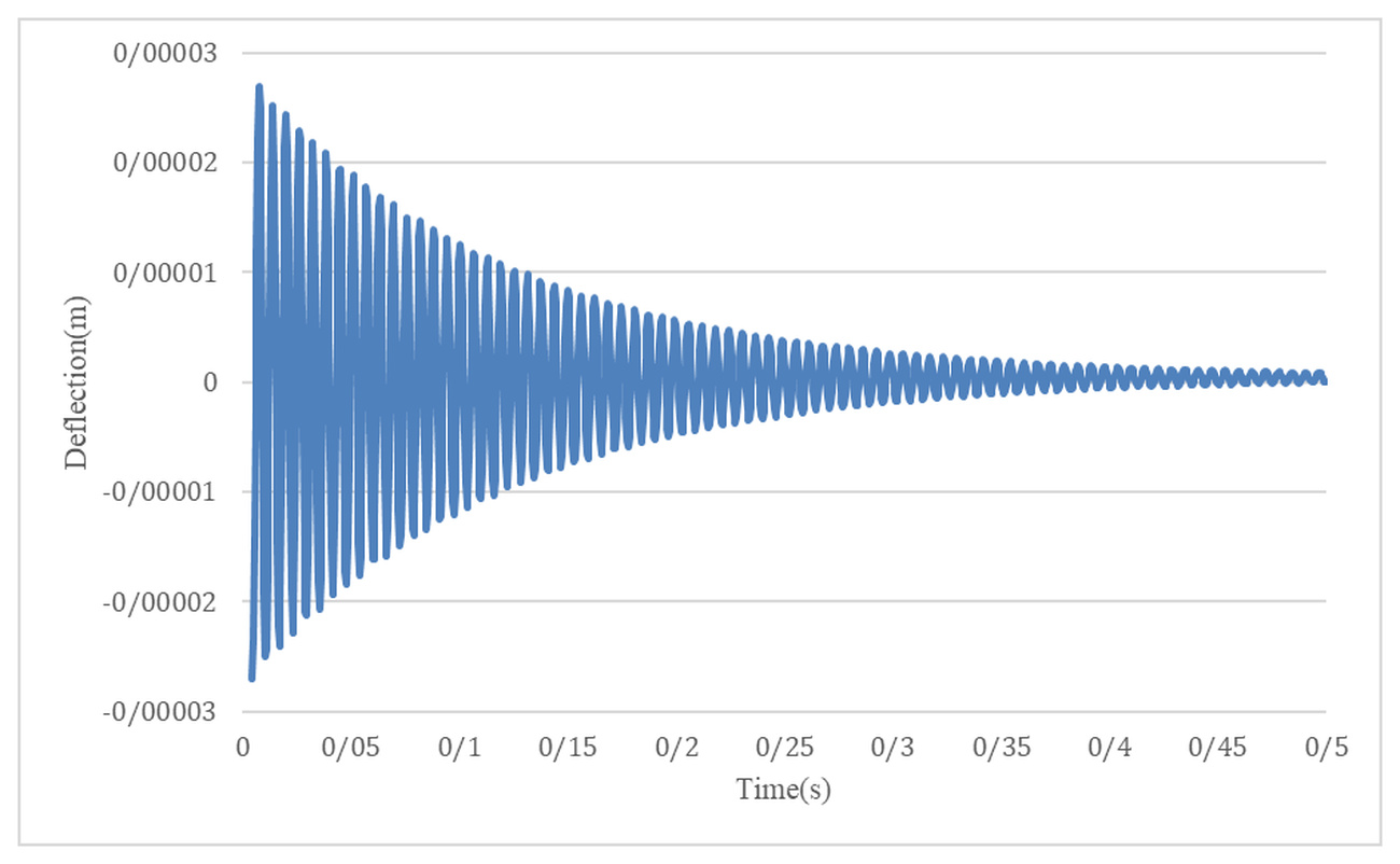
Example 2 In this case, the dynamic response is compared with the results presented by Nguyen-Quang et al [12]. They considered the damping effect and modified (3.15) as follows:
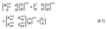
In equation (4.1) the symbols M, C, K and F represent the mass matrix, structural damping matrix, stiffness matrix, and external force, respectively. Since the structural damping value is not available, its magnitude is estimated using the Rayleigh-Ritz method, which defines the stiffness matrix as:

The values of M and K have been defined earlier,

where
The FGPM plate with simply supported boundary conditions which is
studied here consists of two materials surrounded by a piezoelectric
layer Fig.1.(b). The plate is square-shaped, with each side measuring
200 millimeters. The thickness of the intermediate composite plate is
one millimeter, and the thickness of the piezoelectric layer is 0.1
millimeters. The value of the power law constant, n, is assumed to be
2. Additionally, a distributed load
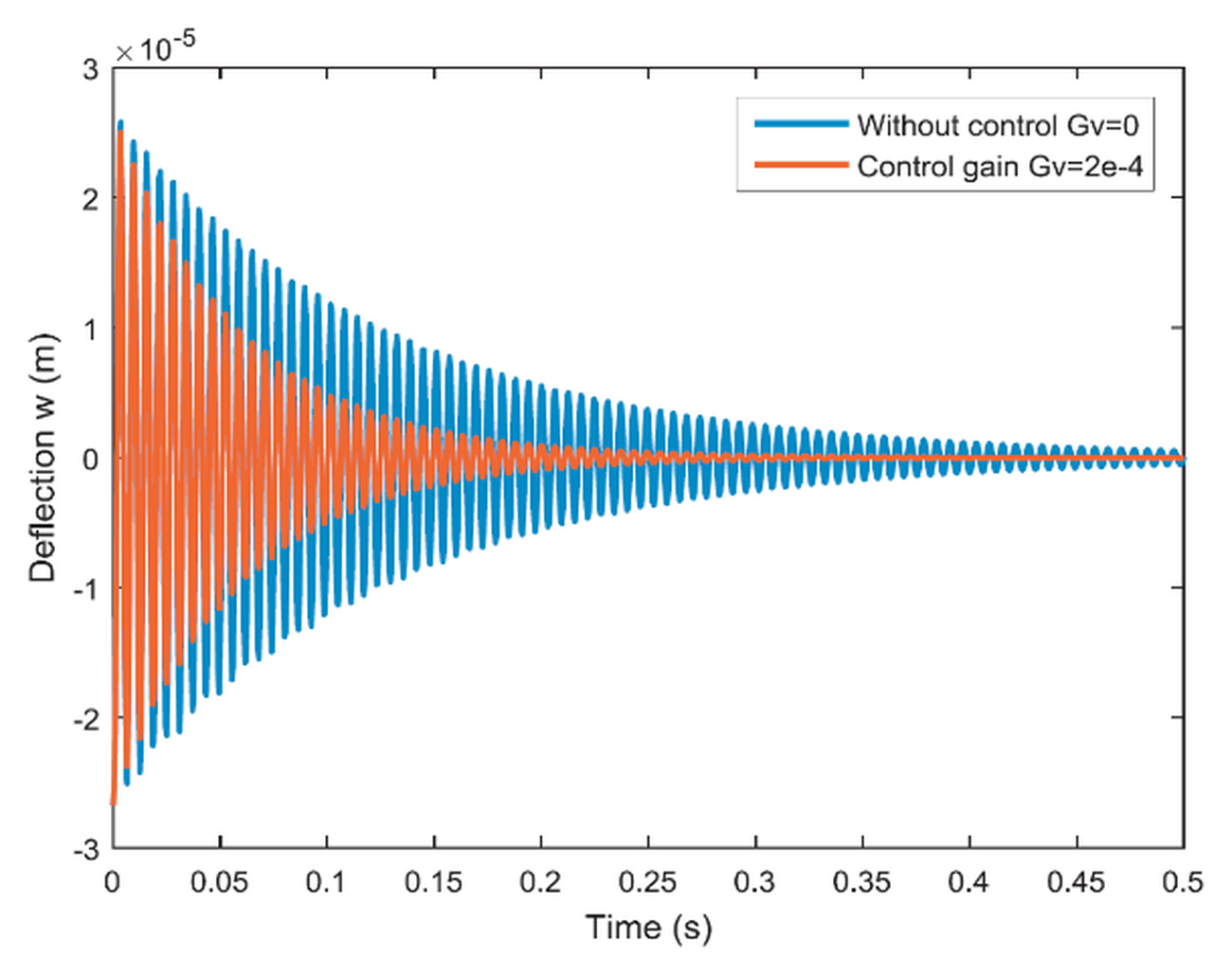
Fig. 4. Dynamic response of FGPM plate presented by Nguyen-Quang et al [12]. Figure in colour only on the web site of the journal
Dynamic Response Analysis
In this section, the dynamic response of the FGPM plate is investigated. For this purpose five variables are introduced and examined based on dynamic behavior of plate as following:
“n” is the power law index, Δss is the maximum displacement of the plate obtained from static analysis, Δsd is the maximum displacement of the plate in the first vibration mode, Δsd/ Δss is the ratio of the maximum displacement in the first vibration mode to the maximum displacement from static analysis, Δt10% is the time taken for the maximum dynamic displacement of the plate to reach 10% of the maximum displacement in the first vibration cycle. The aforementioned variables have been investigated for all introduced types of layer-wise FGPM plates.
The dynamic response of the Functionally Graded Piezoelectric plate for different parameters under mechanical loading
In this section, we first obtain the dynamic response for different
power law constants and clamped boundary conditions. Throughout the
problems investigated in this section of the paper, the values of γ
and β are assumed to be 0.5 and 0.25, respectively. The applied force
on the plate is denoted as
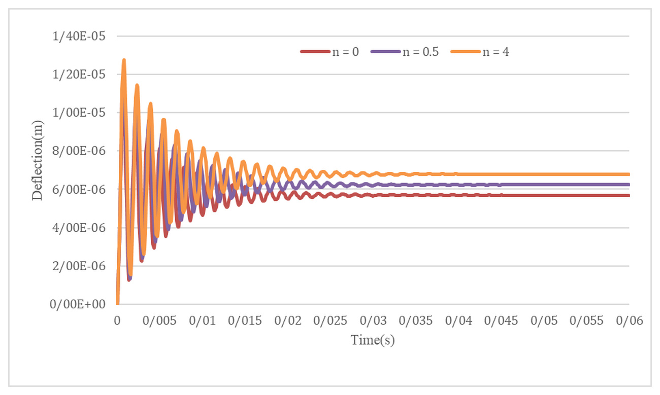
The force is suddenly applied. The time interval for problem solving is considered from t = 0s to t = 0.1s. In this particular problem, the dimensions of the square plate are 0.4 meters, and its thickness is 0.02 meters. The composite plate is composed of a combination of two piezoelectric materials. The properties related to these materials are provided in Table (1). As evident from Fig.6, the maximum dynamic displacement increases with an increase in the power law constant. In this problem, PZT-4 is located at the top and G-1195N is located at the bottom of the FGPM plate. Due to the higher Young's modulus of PZT-4 and considering equations (1) and (2), the Young's modulus of the equivalent plate decreases with an increase in the power law constant (n). As a result, the Δss. Δsd and Δt10% are increased. Table 3 shows the results of the dynamic response parameters for clamped boundary conditions.
The dynamic response of the Functionally Graded plate with piezoelectric layers under mechanical loading
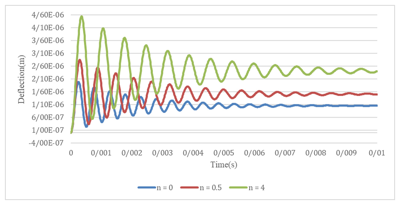
In this part of the dynamic response, the Functionally Graded Plate (FGP) with piezoelectric layers is investigated. This plate consists of a combination of two materials, with Aluminum Oxide on the top and Aluminum on the bottom of the FGP. Additionally, two layers of piezoelectric material are placed on the top and bottom of the plate. The properties of these materials are listed in Tables (1) and (2), respectively. The square plate has dimensions of 0.4 meters and a thickness of 0.02 meters. Furthermore, the thickness of the piezoelectric layer is 2 millimeters. Fig.7 illustrates the dynamic response of the mentioned plate for clamped boundary conditions. Based on the figure, it can be observed that with an increase in the power law exponent and consequently a decrease in the plate stiffness, the maximum dynamic displacement of the plate increases. Tables (3) presents the dynamic response variables of the Functionally Graded Plate with piezoelectric layers under the clamped boundary conditions for different power law exponents.
The dynamic response of the Functionally Graded Piezoelectric plate with PZT-4 and G-1195-N piezoelectric layers
First, the dynamic response associated with the Functionally Graded Piezoelectric Plate with two piezoelectric layers, PZT-4 and G-1195N are obtained. The properties of these materials are provided in Table (1). The plate is square-shaped, with each side measuring 20 centimeters. The thickness of the Functionally Graded Plate is 10 millimeters, and the thickness of each piezoelectric layer is 0.5 millimeters. Fig.8 illustrates the dynamic responses of different configurations of piezoelectric layer placement for n = 0.5. According to this figure, the maximum value of dynamic displacement corresponds to the configuration where the piezoelectric layer (G-1195N) is placed both on the top and bottom of the Functionally Graded Piezoelectric Plate. Conversely, the minimum value of dynamic displacement is observed when the piezoelectric layer (PZT-4) is positioned on the top and bottom of the Functionally Graded Piezoelectric Plate. Additionally, Table (4) provides the dynamic response variables for four different layering configurations of the piezoelectric layer.
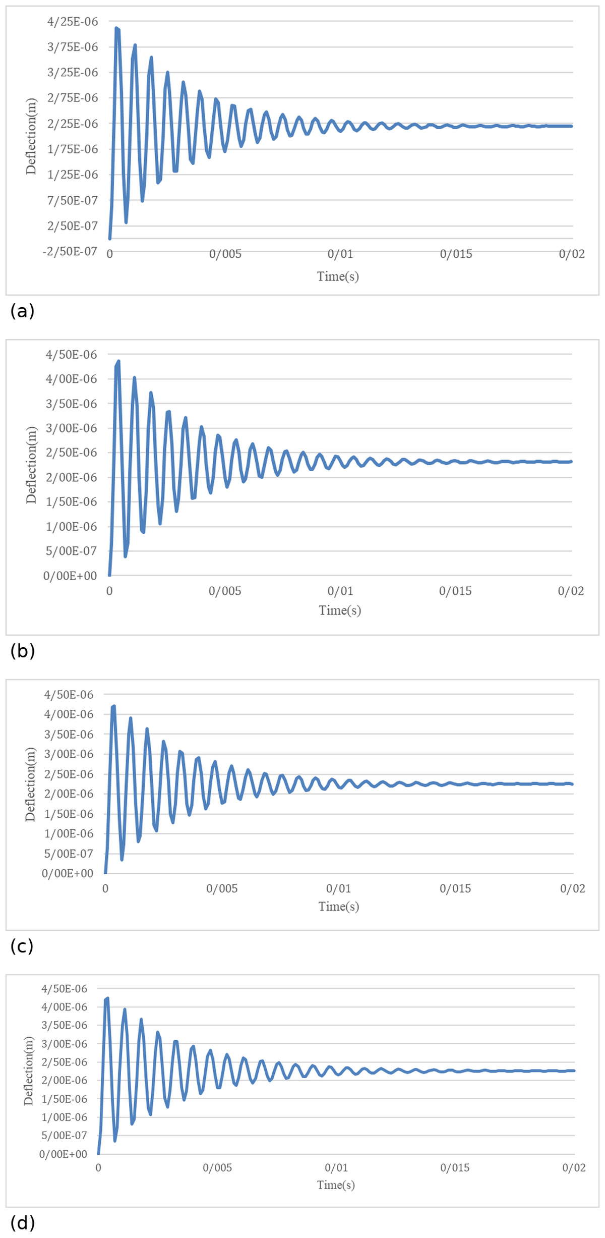
Fig. 8. Dynamic response of the functionally graded piezoelectric plate with piezoelectric layers in different configurations under the clamped boundary condition for n = 0.5: (a) G-1195N layers on top and bottom, (b) PZT-4 layers on top and bottom, (c) G-1195N layer on top and PZT-4 layer at the bottom, (d) PZT-4 layer on top and G-1195N layer at the bottom
Tab. 4
Dynamic response variables of the functionally graded piezoelectric plate with piezoelectric layers for the clamped boundary condition
G1195N-PZT | PZT-G1195N | G1195N-G1195N | PZT-PZT | |
2.2776e−6 | 2.2692e−6 | 2.3326e−6 | 2.2159e−6 | Δss |
4.4053e−6 | 4.3842e−6 | 4.5434e−6 | 4.2804e−6 | Δsd |
1.9341 | 1.9320 | 1.9477 | 1.9316 | Δsd/Δss |
0.0153 | 0.0153 | 0.0149 | 0.0160 | Δt10% |
The dynamic response of the Functionally Graded Piezoelectric plate with Variable Thickness piezoelectric Layers
In this section, the dynamic response of the functionally graded piezoelectric plate with piezoelectric layers on the top and bottom of the plate, considering the variable thickness of the piezoelectric layer is studied. Similar to the previous section, the functionally graded piezoelectric plate is composed of a combination of PZT-4 and G-1195N materials with two layers on the top and bottom. The boundary condition is simply supported, and the value of the power constant is 0.5. The plate is square-shaped with each side measuring 0.2m and the middle functionally graded plate has a thickness of 0.1m.
Tab. 5
Dynamic response variables of functionally graded piezoelectric plate with layers of piezoelectric material having variable layer thickness for a simply supported boundary condition
4 | 2 | 1 | hp (mm) |
2.1566e−6 | 4.2273e−6 | 6.1677e−6 | Δss |
4.1633e−6 | 8.1569e−6 | 1.1934e−6 | Δsd |
1.9305 | 1.9295 | 1.9349 | Δsd/Δss |
0.0183 | 0.0185 | 0.0188 | Δt10% |
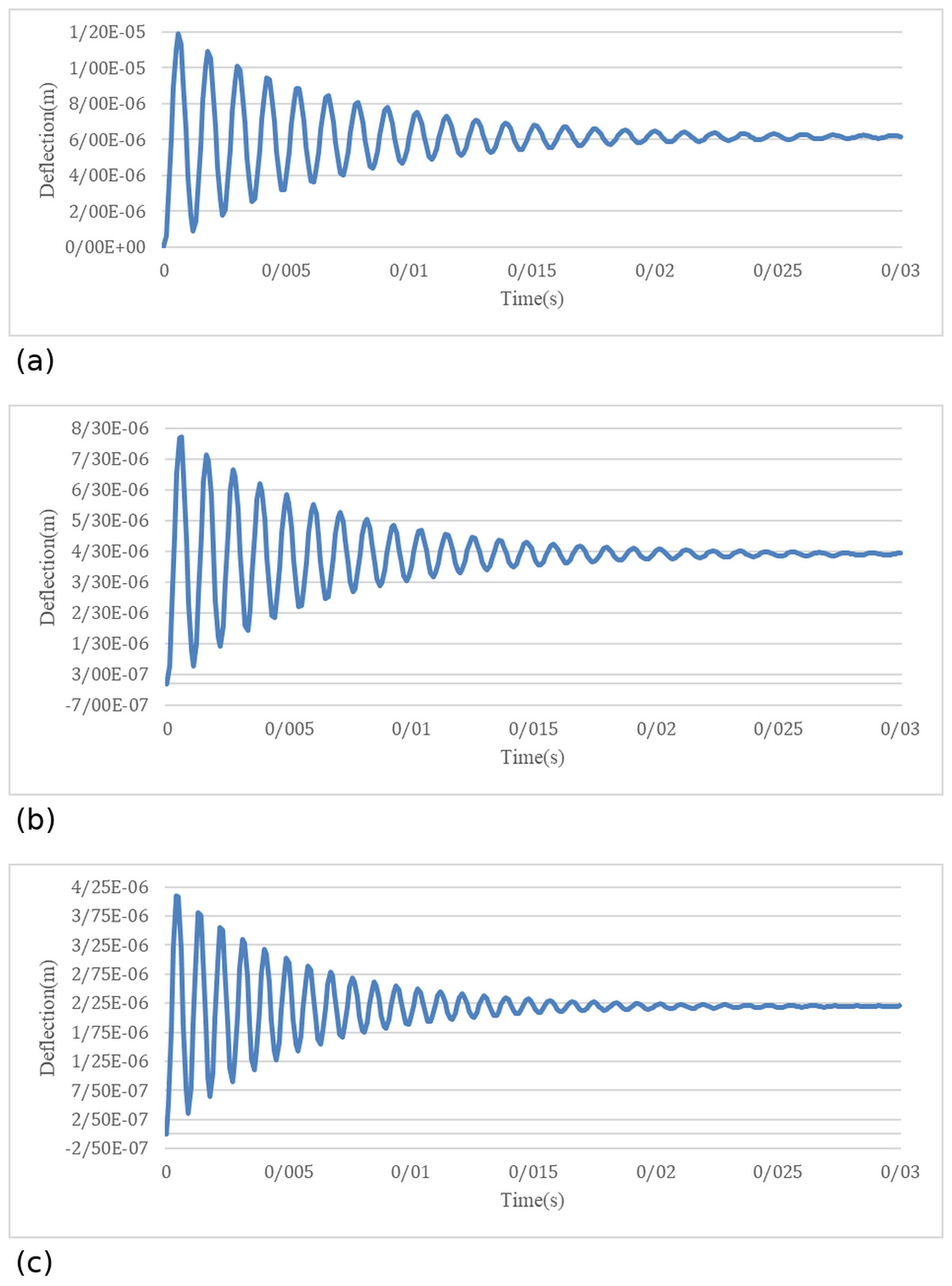
Fig. 9. Dynamic responses of FGPM with piezoelectric layers under simply supported boundary condition and constant power law n=0.5 with variable piezoelectric layer thickness: (a) hp=1mm, (b) hp=2mm, (c) hp=4mm
From Fig. 9, it can be observed that with an increase in the thickness of the piezoelectric layer, the maximum displacement of the plate decreases. This is due to the overall increase in plate thickness, resulting in a stiffer plate.
Furthermore, with an increase in the thickness of the piezoelectric layer, the matrix K becomes larger, and according to equation (26), the matrix C increases. As a result, the plate exhibits faster damping, as depicted in Fig.9. Table (5) presents the dynamic response variables for the aforementioned plate.
The dynamic response of the Functionally Graded plate with piezoelectric layers under Electrical loading
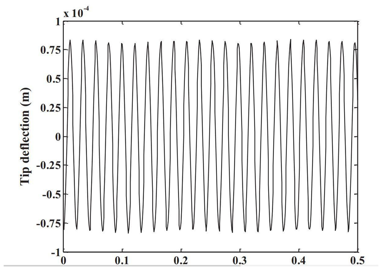
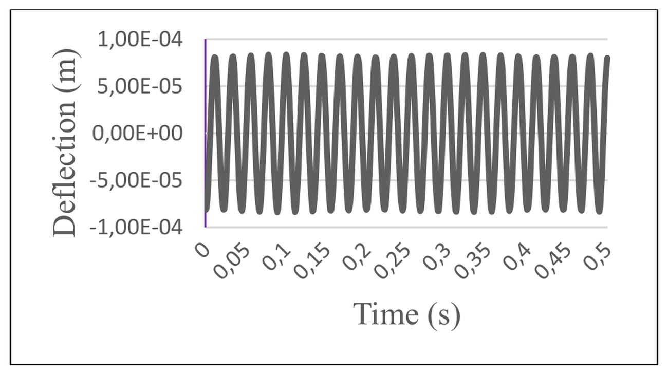
The plate consists of a combination of Ti-Al-4V and Aluminum Oxide. A schematic representation of this plate is shown in Fig. 10. The plate has G-1195N (piezoelectric material) layers on both the top and bottom surfaces. The properties of these materials are provided in Tables 1 and 2. The plate is square-shaped, with each side measuring 400 millimeters. The thickness of the intermediate layer is 5 millimeters, and each piezoelectric layer has a thickness of 0.1 millimeters. One end of the plate is clamped, and an electrical load of 10 volts is applied. In this analysis, both piezoelectric layers are considered as actuators, with the applied voltage having opposite signs in the direction of the piezoelectric layer thickness.
As depicted in Fig.11, the dynamic displacement of the plate decreases with an increase in the maximum power law exponent, indicating the stiffening of the plate for this increment. Moreover, an increase in the power law exponent results in faster damping of the plate's vibrations. Table (6) illustrates the dynamic response variables of the aforementioned plate at different power law exponents. In this analysis, the value of Δt is set to 0.0005, and the problem is solved for t ranging from 0 to 0.5.
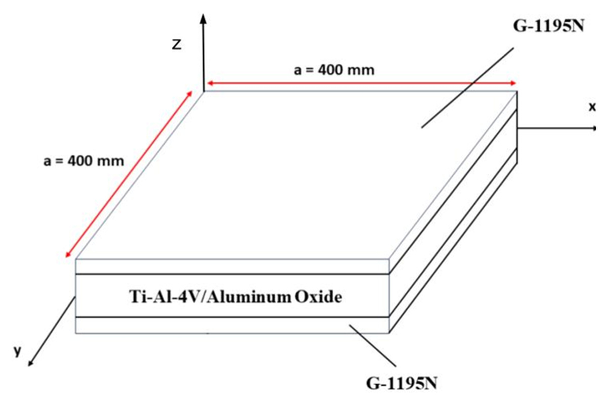
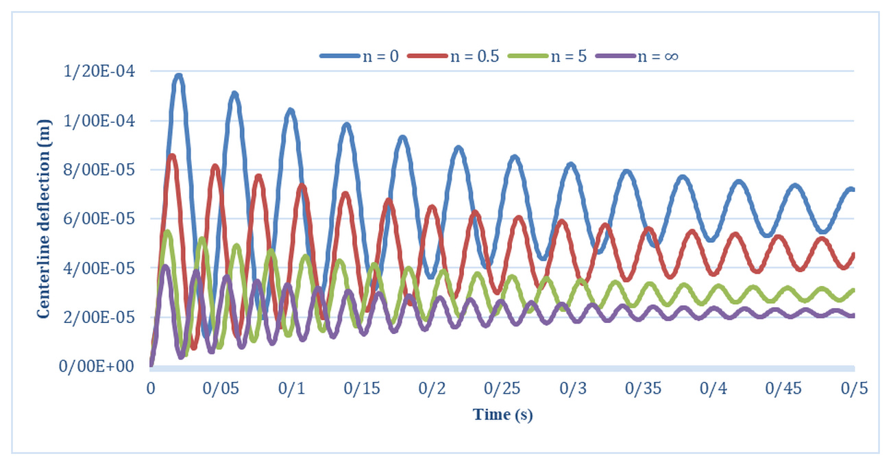
Fig. 11. Dynamic response of the functionally graded plate with piezoelectric layers under an electrical load of 10 volts. Figure in colour only on the web site of the journal
Tab. 6
Dynamic response variables of the functionally graded plate with piezoelectric layers under an electrical load with clamped boundary condition
n = ∞ | n = 5 | n = 0.5 | n = 0 | n |
2.1223e−5 | 2.8619e−5 | 3.9718e−5 | 6.2351e−5 | Δss |
4.0707e−5 | 5.4801e−5 | 7.5992e−5 | 1.1937e−4 | Δsd |
1.9180 | 1.9148 | 1.9132 | 1.9144 | Δsd/Δss |
0.238 | 0.269 | 0.3145 | 0.438 | Δt10% |
CONCLUSIONS
In this study, the dynamic response of functionally graded piezoelectric plates was investigated using the finite element method based on the first-order shear deformation theory. Through comprehensive analyses of various parameters and boundary conditions, several important conclusions were drawn.
By increasing the power law index in both FG and FGP plates with piezoelectric layers under mechanical loading, the plates experience a longer time period before losing 90% of their maximum displacement. This delay is primarily attributed to a reduction in the plate's stiffness, which subsequently leads to a decrease in the system's damping. This reduction in damping is a direct consequence of the increased power law index
In both FG and FGP plates with piezoelectric layers, increasing the power law index results in an increase in Δss and Δsd .
According to different configurations and the adding of piezoelectric layers to the FGP plate, the maximum value of dynamic displacement occurs when the piezoelectric layer (G-1195N) is placed both on the top and bottom of the Functionally Graded Piezoelectric Plate. In contrast, the minimum dynamic displacement is observed when the piezoelectric layer (PZT-4) is placed on the top and bottom of the plate. When both PZT-4 and G-1195N are added to the plate, the dynamic displacement value falls between the two previous configurations.
For different thicknesses of piezoelectric layers, it can be observed that as the thickness of the piezoelectric layer increases, the maximum displacement of the plate decreases. Furthermore, as the thickness of the piezoelectric layer increases, the stiffness matrix (K) becomes larger and the damping matrix (C) increases, resulting in faster damping of the plate's vibrations.
Under electrical loading, Δss and Δsd decrease with an increase in the maximum power law exponent, indicating the stiffening of the plate for this increment. Moreover, an increase in the power law exponent results in faster damping of the plate's vibrations.
This study emphasizes the importance of considering material composition, thickness, aspect ratio, and boundary conditions in the design and analysis of functionally graded piezoelectric plates. The findings can guide engineers and researchers in developing more efficient and reliable structures in areas such as aerospace, energy harvesting, and vibration control. Future research may focus on exploring additional parameters and advanced numerical techniques to further enhance the understanding and optimization of these materials. The outcomes of this study have direct relevance to the design of advanced smart structures, where functionally graded piezoelectric plates can be applied in aerospace components for vibration suppression, in energy harvesting devices for improved efficiency, and in precision sensors or actuators for biomedical and industrial applications. By clarifying how material gradation and electrical loading affect dynamic behavior, the findings provide practical guidance for engineers to optimize stiffness-to-weight ratios, enhance durability, and achieve reliable performance in real-world environments.