INTRODUCTION
Tuned mass dampers (TMDs) are structural control devices designed to vibrate at the same resonant frequency as the structure to counteract sway induced by earthquakes or wind. It acts as a secondary system that absorbs kinetic energy from the main structure and dissipates it through a damping mechanism. These are primarily used in tall buildings, slender structures, and long-span bridges to mitigate lateral vibrations. TMDs significantly reduce maximum displacement and acceleration during seismic events and high winds. The effectiveness of these TMDs depends on optimising the mass ratio, frequency ratio and damping coefficient.
The three different approaches to passive structural vibration control—conventional beam tuned mass dampers (TMDs), eddy current dampers (ECDs), and metallic damping systems differ mainly in their energy dissipation process, kind of contact, and maintenance requirements. To absorb energy, conventional beam TMDs use mass-spring-damper systems that are adjusted to a particular frequency. Eddy Current Dampers (ECDs) are perfect for high-endurance, maintenance-free applications because they provide non-contact damping by inducing electrical currents utilising magnetic fields. Often used as sacrificial, interchangeable parts, metallic damping systems (also known as metallic yield dampers) release energy by the plastic deformation (yielding) of metal components. Cantilever beams, which have one fixed end and one free end, are commonly used in bridges, overhangs, balconies, and mechanical components. Because these beams can tolerate bending moments and shear stresses from loads applied at the free end or along their length, they are ideal for large spans without intermediate supports [40].
TMDs are widely used in machinery, aerospace, civil engineering, and other related fields to control structural vibrations generated by environmental loads such as wind, earthquakes, and traffic [1–3]. As passive vibration-control devices, TMDs dissipate or redistribute vibration energy through proper tuning. A typical TMD system consists of a mass, spring, and damper attached to the structure to reduce its dynamic response [4]. They are frequently employed to mitigate low-frequency vibrations in bridges, reduce ship motions, control auxiliary vibration energy transfer, and limit noise leakage in floating-raft structures [2]. TMDs are highly effective in suppressing structural responses under various external loads, including wind, traffic, and seismic excitation [5,6].
The design of TMDs requires careful identification of loading characteristics and structural properties [4]. Optimal TMD properties can be determined by considering a variety of objectives, structural types, and excitation conditions [7]. Tuning involves performing a dynamic analysis of the structure and optimising TMD parameters for maximum performance [5]. Because they are reliable, efficient, and require minimal maintenance, TMDs are widely adopted for improving comfort in buildings and bridges, reducing amplitude responses, and enhancing structural safety by limiting induced motion and associated fatigue problems [6].
However, uncertainties in structural parameters or environmental loads can compromise TMD performance [3]. While the use of TMDs is recognized as the most effective method for suppression of vibrations [25], their narrow effective frequency band remains a key limitation in many engineering applications [9]. Thus, although TMDs offer significant advantages—such as reliability, efficiency, and ease of implementation—they also exhibit performance constraints under certain conditions [11–13]. Additionally, materials having high impact strength are often preferred in TMD design, as they can withstand sudden stresses without failure [14,15].
Damping mechanisms that hinge on sliding friction, material yielding, viscous fluid, and particle collision have been subject to extensive investigations, and applications should be inside actual buildings and bridges [16], [17], [18], [19], [20], [21].
The effectiveness of control of TMD decreases as its frequency deviates from the natural frequency of the structure [22]. Hence, the natural frequency of the TMD must be designed and tuned to a particular range to it resonate out-of-phase with the main structure [23]. The copper barrier material can be applied inside the cabin on the metallic parts for the reduction of vibration [24].
At resonance, SMID cannot suppress forced vibration amplitude as effectively as a TMD [26]. However, without the damper element in the TMD, the Entire system becomes very sensitive to slight mistuned conditions [26], [27], [28].
The TMDs are widely used because of their simple characteristics, low cost, convenient installation, and favourable control effects at specific tuning frequencies [29]. The damping mechanism of particle dampers has not been thoroughly understood due to their increased nonlinearity [30],[31].[32],[33],[34].
The pendulum device is one of the various TMD geometries [36]. The application of inertial forces of additional weights is a popular technique for passive vibration control of beams and plates [37]. The correct choice of the TMD's mass, stiffness, and damping properties is crucial to its efficacy [38]. Large cantilevered sidewalks reduce the amount of area occupied beneath the bridge while giving pedestrians greater room to move about. As a result, it finds extensive use in bridges that span rivers, valleys, or city streets [39].
Copper acts as a conductive material in conjunction with permanent magnets. The relative motion between these two materials creates a magnetic eddy current that provides a damping force, which acts as a non-contact vibration-damping system. Variable-thickness copper plates can be used to create two-stage or tunable damping parameters.
Because of its high electrical conductivity, which increases the magnetic damping force, copper is frequently used in Eddy Current Dampers (ECDs). In order to produce better eddy-current damping than conventional passive TMDs (steel/springs), a study employing "Copper TMDs" functioning as a passive electromagnetic damper. The study focuses on using this particular damping mechanism to address the distinct modal characteristics of a single-stage cantilever beam, which is a typical archetype for turbines, structural cantilevers, and aircraft parts. The work frequently emphasises a low-contact or non-contact damping strategy, which avoids structural flaws occasionally connected to physical contact dampers. In contrast to conventional friction or rubber dampers, the study presents a high-performance passive damping system (Copper TMD) that uses eddy current phenomena for enhanced vibration suppression on cantilever structures. These TMDs provide resilient, low-maintenance, and highly efficient structural seismic control systems by using copper for eddy current dampening and creating adaptive mechanisms.
The remainder of this paper is organised as follows: Section 2 derives the novelty of the present study. Section 3 introduces the experimental setup used for the investigation. Section 4 describes the experimental investigations on free and forced vibrations with or without the copper beam. Section 5 provides the discussion on the results obtained from the experimental studies. Finally, section 6 summarizes the main conclusions of the study.
NOVELTY OF THE WORK
TMDs are extensively used in structural vibration moderation because of their ability to absorb and dissipate dynamic energy by oscillating out of phase with the primary structure. Conventional TMD configurations usually depend on masses and discrete spring–damper assemblies, which limit their adaptability and efficiency in certain applications. The present study introduces a new approach by using a copper beam as an integrated TMD, thus transforming a structural element into an effective passive control device.
Copper material offers distinct advantages when configured as a beam-type TMD, with its inherent high density, favourable stiffness characteristics, and excellent damping capacity. In this work, the copper beam is exactly designed to resonate at the dominant natural frequency of the host cantilever system. This confirms optimal energy conversion between the primary structure and the damper. It leads to significant attenuation of vibration amplitudes. The proposed configuration not only enhances damping performance but also eliminates the requirement for conventional mass–spring assemblies, resulting in a more compact, structurally compatible, and efficient vibration control mechanism.
The novelty of this work lies in:
− The innovative use of a copper beam as a functional TMD,
− A resonance-based tuning strategy,
− A simplified and integrated TMD architecture.
This method provides new insights into beam-type TMD design and demonstrates the potential of material-based tuning solutions for advanced vibration suppression in mechanical and structural systems.
EXPERIMENTAL SETUP
Primary Structure: This can be a simple beam, a multi-degree-of-freedom frame structure, or a model representing a real structure.
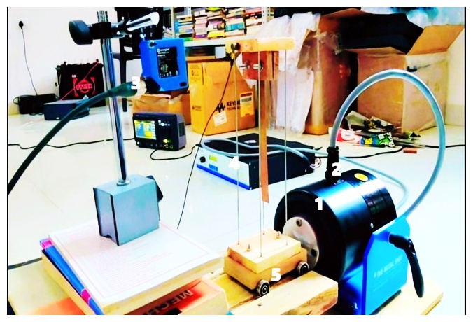
Tuned Mass Damper (TMD): This consists of a spring, mass, and a damper. A TMD is connected to the primary structure at a specific location using a spring and damper element, as shown in Figure 1.
Shaker: The shaker device provides an excitation force to vibrate the structure.
Mount the sensors: Accelerometers or displacement transducers were mounted on the structure and TMD mass to measure their vibrations.
Data Acquisition System (DAQ): This system records the vibration responses of the structure and TMD mass. This typically includes sensors (accelerometers and displacement transducers) and data loggers. The sensors were connected to a data logger or data acquisition system to record the vibration data during the experiment.
An actual structure was modelled using a main structure. As seen in Fig. 1, a modal shaker system is used to provide the structure with an artificial vibration. The structure is equipped with accelerometers and a TMD mass. The data measured during experimental work is stored in a DAQ system. The measured frequency of the experimental setup is analysed using DEWESOFT software. First, without using the TMD mass, the vibration and frequencies are derived for both pushed and free instances. The TMD mass in the structure was used to repeat the experiment. We tabulate and compare the measured frequencies.
EXPERIMENTAL WORK
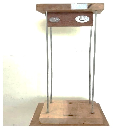
The experimental data is obtained after experimenting on the cantilever beam. The characteristic curves were recorded in DEWESOFTX. The experimental data were imported into DEWESOFTX, and the corresponding time domain and frequency domain analysis (using FFT) of the experimental data were analyzed so that the relevant natural frequencies could be calculated. Tab. 1 shows the material and geometric properties of the beam used for the experimentation. Fig. 2 shows a homogeneous copper beam mounted on the shaker.
Tab. 1
Specification of a single-stage without a copper beam natural frequency
Material | Model Length (l) in mm | Model Width (b) in mm | Model Thickness and Dia of rod in mm | Mass of the Model in grams |
Wood | 100 | 80 | 15 | 0.204 |
Steel rod | 270 | - | 2 | 0.020 |
Experimental analysis of a single stage without a beam
Free vibration analysis
Fig. 3 (a) shows the typical time-domain response of a beam under free vibration, after excitation by an initial excitation. The graph shows the displacement of a single-stage structure over time, with a decay in amplitude due to the damping characteristics of the material.
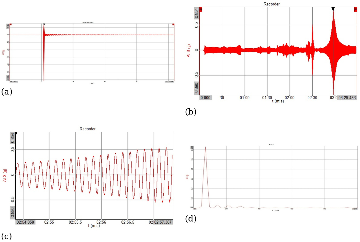
Fig. 3. (a) time domain response of single stage graph without beam, (b) forced vibration analysis in DEWESOFTX, (c) time domain graph of single stage without beam, (d) frequency response of forced vibration without beam (media)
The typical methods used to measure the natural frequency are as follows:
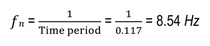
Initial time = 7.01, Final time = 8.35, No. of cycles = 10
Then, by using the log decrement method,

Forced Vibration Analysis
The same single-stage structure model was mounted on a shaker to perform the forced vibration tests. Fig. 3(b) shows the frequency response of the beam under a forward sweep. Figure 3(d) shows the frequency response of the structure under a forward sweep, as seen in the DEWESOFTX data file. Fig. 3(c) shows a magnified view of the response of the structure for a given input of 0.854 g amplitude by the shaker. The amplitude of the vibration response increases as frequency approaches the natural frequency and then decreases as frequency moves away from the peak level. This behavior is expected for a structure in a forced vibration test, and the natural frequency of the beam is found to be 7.32 Hz. There was a marginal difference in measuring the natural frequency of the structure with a free and forced vibration test of 1.22 Hz.
Reducing the vibration of a single-stage structure
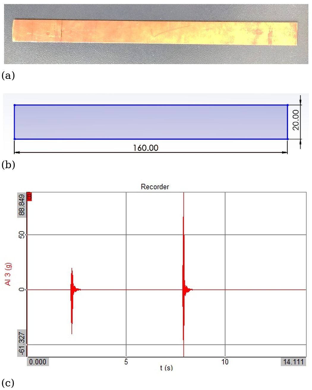
For minimizing the vibration of a single-stage structure, the copper beam is used as the medium that observes the vibration of the structure and transfers the vibration to the copper beam, which reduces the acceleration of that structure, as shown in Fig. 4 (a) and 4 (b).
To reduce the vibration, the natural frequency of a single stage was matched to the media of the copper beam for the required length of the beam, as shown in Table 3.
Tab. 3
Specification of the copper beam as a TMD
Material | Mass (gm) | Length of beam (mm) | Width of the beam (mm) | Thickness of beam (mm) |
Copper | 0.016 | 160 | 20 | 0.5 |
Fig. 4 (c) shows the typical time-domain response of the copper beam under free vibration after initial excitation. The graph shows the displacement found in the copper beam over time with a decay in amplitude owing to the damping properties of the material.
The typical methods used to measure natural frequency are as follows:
Initial time = 1.181, Final time = 2.280, No. of cycles = 10
Then, by using the log decrement method,

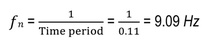
Hence, it is observed that the natural frequency of the copper beam nearly matches the frequency of a single-stage structure.
Experimental Analysis of Single Stage with Beam (media)
Fig. 5 (a) shows the typical time-domain response of the copper beam under free vibration- after initial excitation. The graph indicates the displacement of a single-stage structure with a copper beam as a (media) over time, with decay in amplitude owing to the damping properties of the copper material, as shown in Tab. 4.
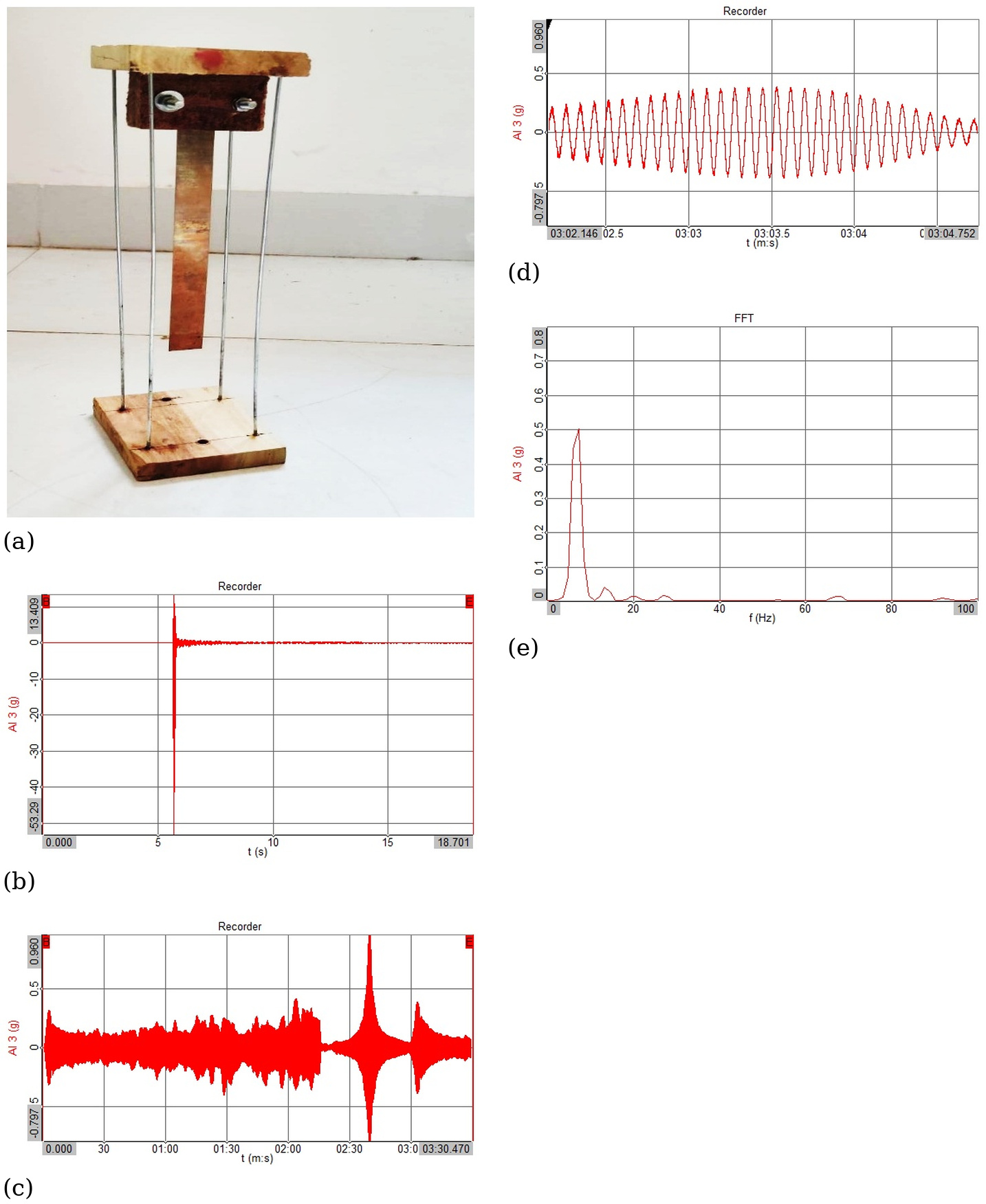
Fig. 5. (a) Experimental Analysis of Single Stage with Beam (media), (b) Time Domain Response of Single Stage Graph with Beam (media), (c) Forced Vibration Analysis in DEWESOFTX, (d) Time Domain Graph of Single Stage with Copper Beam (media), (e) Frequency Response of Forced Vibration with Beam (media)
Tab. 4
Specification of a single stage with a copper beam as a TMD
Material | Length of the Model (l) in mm | Width of the Model (b) in mm | Thickness and Dia of the rod of the model in mm | Mass of the Model in grams |
Wood | 100 | 80 | 15 | 0.204 |
Steel rod | 270 | - | 2 | 0.020 |
Copper beam | 160 | 20 | 0.5 | 0.016 |
Free vibration
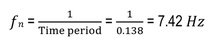
The single-stage structure model with a copper beam was mounted on the shaker to perform the forced-vibration test. Fig. 5(b) shows the frequency response of the beam under a forward sweep. Typical methods used to measure the natural frequency are as follows:
Initial time = 4.362, Final time = 5.741, No. of cycles = 10
Then, by using the log decrement method,

Forced Vibration Analysis
Fig. 5 (c) shows the frequency response of the structure under a forward sweep, as seen in the DEWESOFTX data file. Fig. 5 (c), 5 (d) and 5 (e) show a magnified view of the response of the structure for a given input of 0.534 g amplitude by the shaker. The amplitude of the vibration response increased as the frequency of the structure approached the natural frequency and then decreased as the frequency moved away from the peak. This behaviour is expected for a structure with a forced vibration test, and the natural frequency of a beam was found to be 7.324 Hz.
RESULTS AND DISCUSSION
The comparison is made for frequencies found in free and forced vibrations in single-stage structures without and with a beam, as tabulated in Tab. 5 and Tab. 6 below.
Tab. 5
Comparison of experimental results of free and forced vibration analysis of a single-stage structure without a copper beam
Material | Experimental Result | Experimental Result | Experimental Result |
Material | Free Vibration Natural Frequency (Hz) | Forced Vibration Natural Frequency (Hz) | Amplitude (g) |
Wood and Steel Rod | 8.54 | 7.32 | 0.85 |
Tab. 6
Comparison of experimental results of free and forced vibration analysis of a single-stage structure with a copper beam
Material | Experimental Result | Experimental Result | Experimental Result |
Material | Free Vibration Natural Frequency (Hz) | Forced Vibration Natural Frequency (Hz) | Amplitude (g) |
Wood and Copper beam | 7.42 | 7.32 | 0.53 |
From the above table, it is observed that in the single-stage structure with the copper beam, the natural frequency in the forced vibration test is measured as 7.32 Hz. It was discovered that there was good agreement between the natural frequency results obtained from the forced and free vibration testing with and without the media. A single-stage structure's inherent frequency dropped both with and without the beam, and the trend was comparable. This approach in conducting the experiment for measuring the natural frequencies using TMD’s can be extended to multistage structures.
CONCLUSION
An investigation was carried out to understand how a tuned mass damper (TMD) affects the natural frequencies of structural systems. In this study, a copper beam was used as the TMD.
The following conclusions were drawn from the present study.
– The natural frequency of the single-stage system without the beam was measured as 8.54 Hz, while the addition of the copper beam reduced the natural frequency to 7.32 Hz.
– Under forced-vibration conditions, the system without the beam exhibited a response frequency of 7.42 Hz, whereas the system with the beam again showed a frequency of 7.32 Hz.
– With the copper as TMD mass, natural frequency was reduced by of 14 % in free vibration and 2% in forced vibration case.
– The close agreement between the analytically obtained and experimentally measured natural frequencies confirms the validity of the approach and indicates that the structure remains stable at these frequencies.
– Furthermore, the inclusion of the copper beam as a TMD effectively reduced the acceleration response of the structure, as observed in the forced-vibration analyses.
It is realized that the use of TMD reduces more vibrations in the structure compared to other damping methods.