
Introduction
Due to the fact that the extrusion process is characterized by, among other things, often complex product geometry and high unit pressures on the tool surface, it often results in rapid wear and even cracking of the dies. In general, the squeezing process is influenced by many parameters [1-3]. In paper [1] effects of process parameters, initial billet temperature, ram displacements, reduction of area, semi-die angle, and friction coefficients are studied. In turn, in paper [2] X-ray diffraction (XRD) and the finite element technique (FET) to measure the residual stresses (RS) inside Al1060 rods produced by forming operation at three different half extrusion angles (HEA = 20°, 40°, and 60°) were applied. Circumferential tensile stresses are particularly dangerous for the extrusion dies. In addition to technological parameters, the life of the dies is also influenced by the material of the tools [4]. The extrusion dies or their inserts are made of steel or cemented carbides. Steel dies are durable but much less resistant to pressure and tribological wear compared to sintered carbide dies. In turn, a signifi1cant disadvantage of cemented carbide dies is their relatively low tensile strength, which, at certain values of circumferential tensile stress, can result in their destruction as a result of cracking.
Cracking as a cause of die failure can be divided into two different groups: over-load crack and fatigue crack. Stress cracking can be caused by high deformation loads that exceed the limited strength of the tool material. These types of failures can be remedied with a good control over molding parameters. The second type of die damage, fatigue cracking, is the result of the tool operating under heavy load conditions. These conditions are favorable for initiating micro-cracks that can start growing [5].
In order to increase the service life of extrusion tools, various methods are used to select the optimal material for the tools, its thermo-chemical treatment and special construction solutions [6-10]. It is worth mentioning that residual stresses occur in materials, including tool material, after the manufacturing process. They can be generated by various mechanisms, and can be compressive or tensile [11-12]. Compressive residual stress can have a very positive effect on the durability and life of machine elements as it acts to counteract the applied tensile stress, keeping the crack surfaces closed, minimizing damage. The studies on residual stresses were undertaken, among others, in [13-15].
A practical method to reduce the stress level in the tool during extrusion is to use pre-compressed dies. Such a die consists of an insert and a compression ring mounted on it with a suitable interference. In engineering practice, two-ring prestressed dies are also used. In the shrinkage ring applied to the die, tensile circumferential stresses and compressive radial stresses are obtained, while in the die the compressive circumferential and radial stresses occur [16].
The concept of pre-stressing is widely used in industry and in many different applications. The general idea is to bring some tool component (e.g. a die) into compression during a tool assembly in order to reduce the level of tensile stresses at maximum process load. Pre-stressing of highly loaded dies in precision metal forging applications, high-pressure industrial diamond synthesis, and high-pressure experimentation are well-known examples of such industrial applications. Pre-stressing is one of several design parameters, but it is usually the key to achieve high performance tooling systems, including the elimination or postponement of die cracking, chipping, wear, or loss of required part tolerances [17-20].
A review of the literature on pre-stressed dies indicates a search for a way to achieve an acceptable tool life. Gorenbaek et al. [21] suggested a versatile pre-stressing mechanism which can produce desirable compressive stress to prolong die life in forging. The authors in [22] studied the effect of the flow stress and strain-hardening of forged materials to predict the service life of forging tools, whereas Lee et al. [23] investigated the effects of different shrink fitting ratios to predict the fatigue life of die insert. In paper [24] the use of carbon fiber composite material for the shrink ring to improve the tool life was considered. An application-oriented finite-element approach to forging die structural analysis was presented in paper [25]. The authors in [26] showed a method of determining the interference between rings and the insert in dies prestressed with rings.
Insert die life can be defined as the number of load cycles the tool withstands before crack initiation begins [27]. Tool failure in cold forming processes is generally caused by breakage. If it is possible to reduce the stresses to a moderate level, as well as to reduce the deforming load, the tool life can in some cases increase even several times [28]. Kawahara et al. [29] suggested the use of master fatigue diagram to predict the fatigue life of die insert. In this paper [30], the authors show that there is a significant relationship between the shrink fitting ratio and the fatigue life of die insert. Thus, a method to identify the optimum shrink fitting ratio by the use of master fatigue diagram is possible to predict the maximum service life of die insert. The failure due to wear is not as common as cracking as the service life is often too short to cause wear failure [31].
When designing a new tool, the aim is to avoid tensile stresses and strains in the critical areas of the die [32-33]. Another design suggestion is to apply only pretension in the tool cavity area instead of preloading the entire length of the tool. This change may result in a significant extension of its work [34]. Tool life prediction can be done in different ways, for instance, by taking local deformation into account. This can predict the approximate tool life, but it is still longer than the actual tool life [27].
Some of the problems encountered in the literature, such as high stress concentrations in the corners near the bottom opening of the insert die, can be solved by enlarging the bottom opening as much as possible. This change can extend the life of the sensor up to five times.
Calculation of stresses in tools can be done using a traditional approach, or using finite element analysis (FEM) [35-37]. If the traditional thick-walled cylindrical approach is used, the calculated stresses in the die and shrink ring assemblies, compared to finite element analysis, predict significantly higher stresses in the tools. If the die geometry of the insert is complex, the traditional approach will not be sufficient and FEM should be used [38-40].
The work concerns a comparative analysis of circumferential stresses (assembly and working) in dies prestressed with one steel ring. The results of preliminary tests for prestressed dies with a carbide insert presented in the paper [41] showed the possibility of reducing the working stresses in the die insert by using a compression ring of an appropriately selected thickness and value of the assembly interference. This gives a measurable benefit in the form of the possibility of increasing the load of the extrusion tools without the need to increase their overall dimensions. These mentioned benefits were the basis to extend the previous tests. The aim of the this research was to check the influence of the type of insert material and the ratio of the insert wall thickness to the thickness of the compression ring on the value of assembly and working stresses. The influence of the interference between the insert and the compression ring on the value this stresses, in the die was also studied. The results of these research for three values of the assembly interference, two materials of the die insert and three values of the ratio of the wall thickness of the die insert to the wall thickness of the compression ring are presented in this paper. The research results featured in this paper provide new knowledge in the field of designing advanced prestressed tools for plastic processing, using the example of a two-stage extrusion die.
Experimental Setup
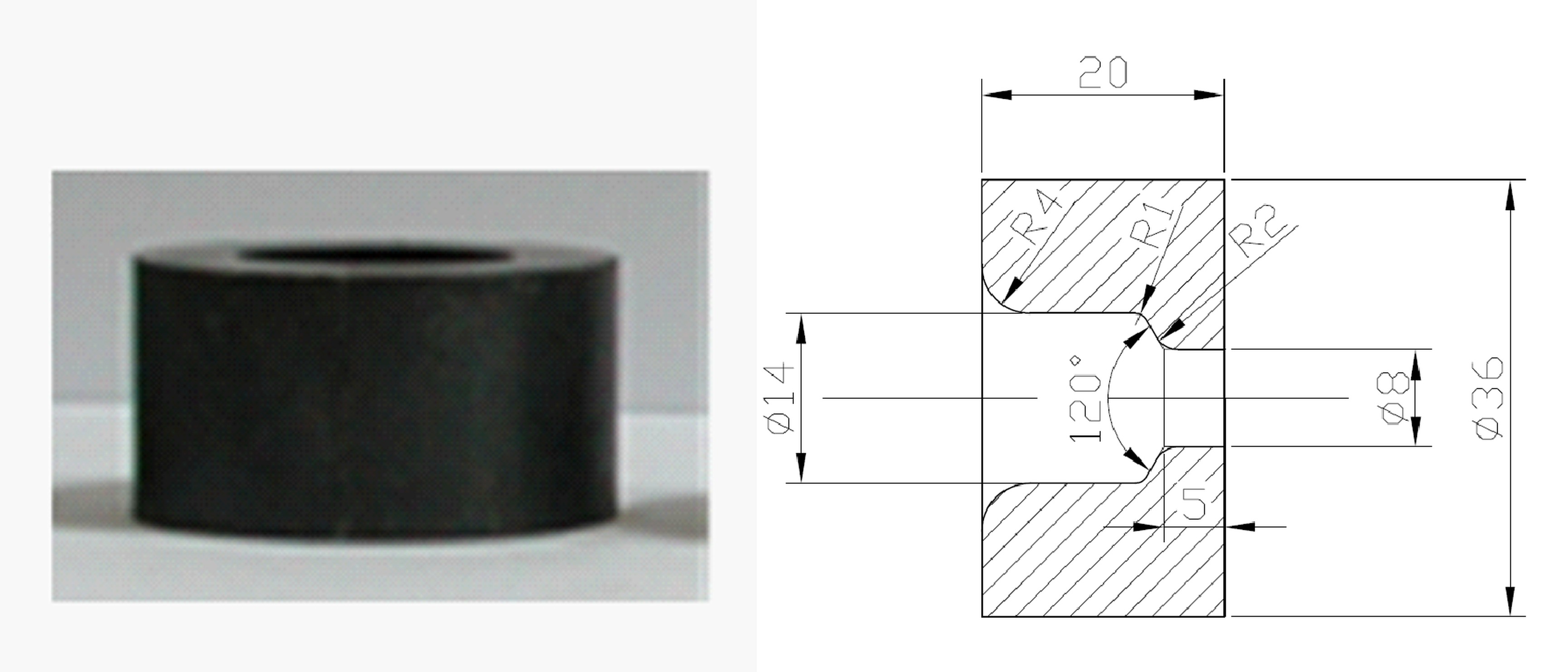
The tool set shown in Fig. 1 was used to carry out the co-current extrusion tests. The shape and dimensions of the steel die used for the tests are shown in Fig 2.
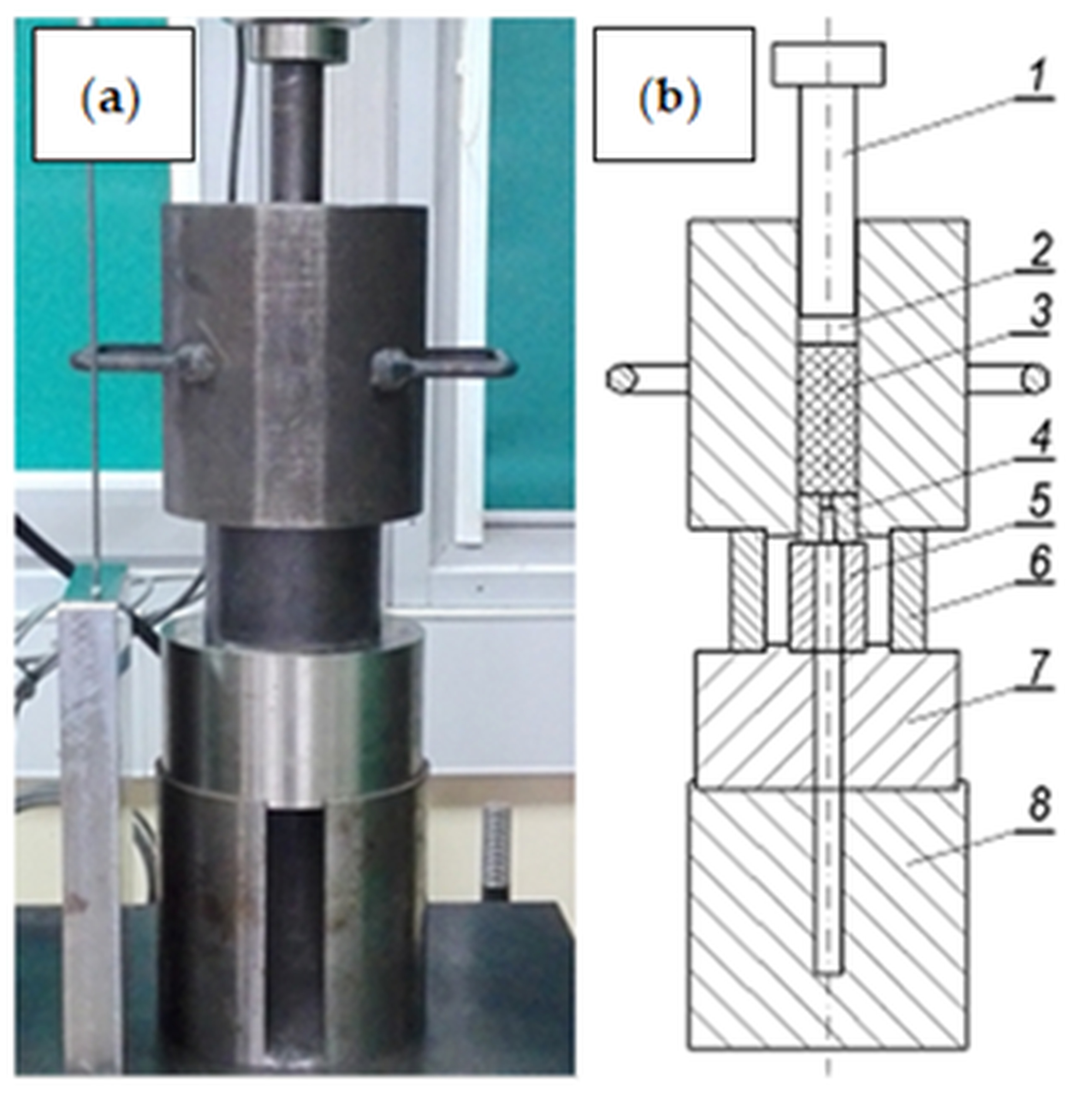
Fig. 1. Extrusion tool set: (a) general view, (b) longitudinal section (1 - punch, 2 - spacer, 3 - extrusion charge, 4 - die, 5 and 6 - spacer sleeves, 7 and 8 - base)
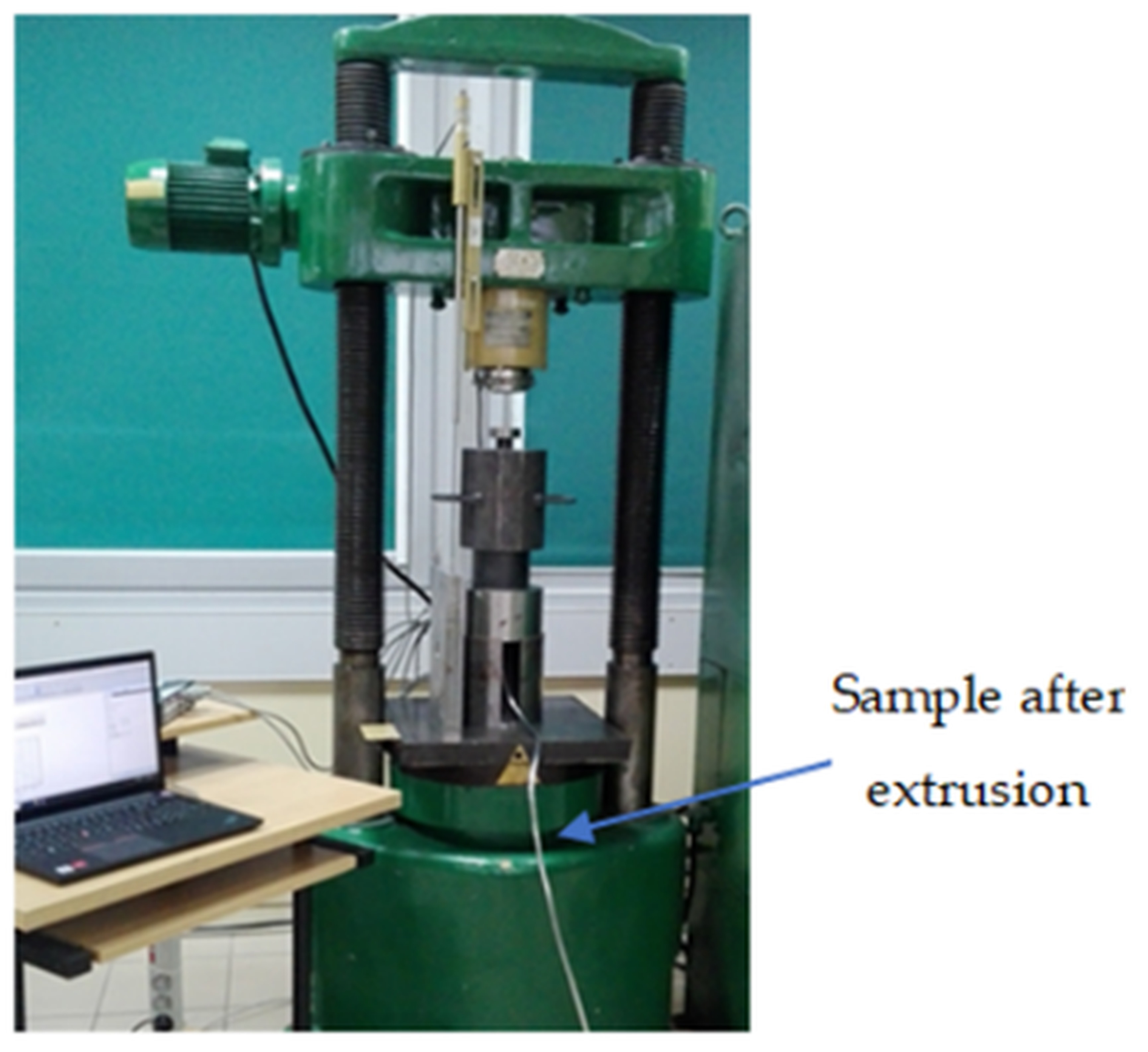
The input material for extrusion was a rod with the diameter of =36 mm and the length of 72 mm made of Pb1 lead, whose properties are listed in Tab. 1. Lead is the metal most often used in experimental research. This material was successfully used, among others, in the analysis of the extrusion process [42-44]. The extrusion was carried out on a stand consisting of a vertical hydraulic press equipped with force and displacement sensors and a measurement data acquisition set consisting of a measuring transducer and a computer (Fig. 3).
Tab. 1
Mechanical and plastic properties of the tested material [45].
| Material | Equivalent plastic strain, p | Yield stress, MPa | Young's modulus E, MPa | Poisson's coefficient |
Lead (99.98%) | 0 | 5 | 18 000 | 0.42 |
0.05 | 10.42 | |||
0.10 | 13.27 | |||
0.15 | 15.59 | |||
0.20 | 17.30 | |||
0.30 | 18.78 | |||
0.40 | 18.72 | |||
0.50 | 18.64 | |||
1 | 19.05 |
Three extrusion tests at a temperature of 20oC were carried out on the stand equipped in this way. Then, the characteristics of the extrusion force as a function of the displacement of the punch were prepared. The course with intermediate values was selected as a representative for further research.
The conducted experimental studies were aimed at verifying the correctness of the numerical model of the extrusion process used for numerical analyses. The correctness of the numerical model described in the further part of the work was verified on the basis of comparing the course and value of the calculated extrusion force to the course of this force determined experimentally. The characteristics of the extrusion force as a function of the displacement of the punch, determined experimentally and calculated in the FEM simulation, are shown in the graph (Fig. 4).
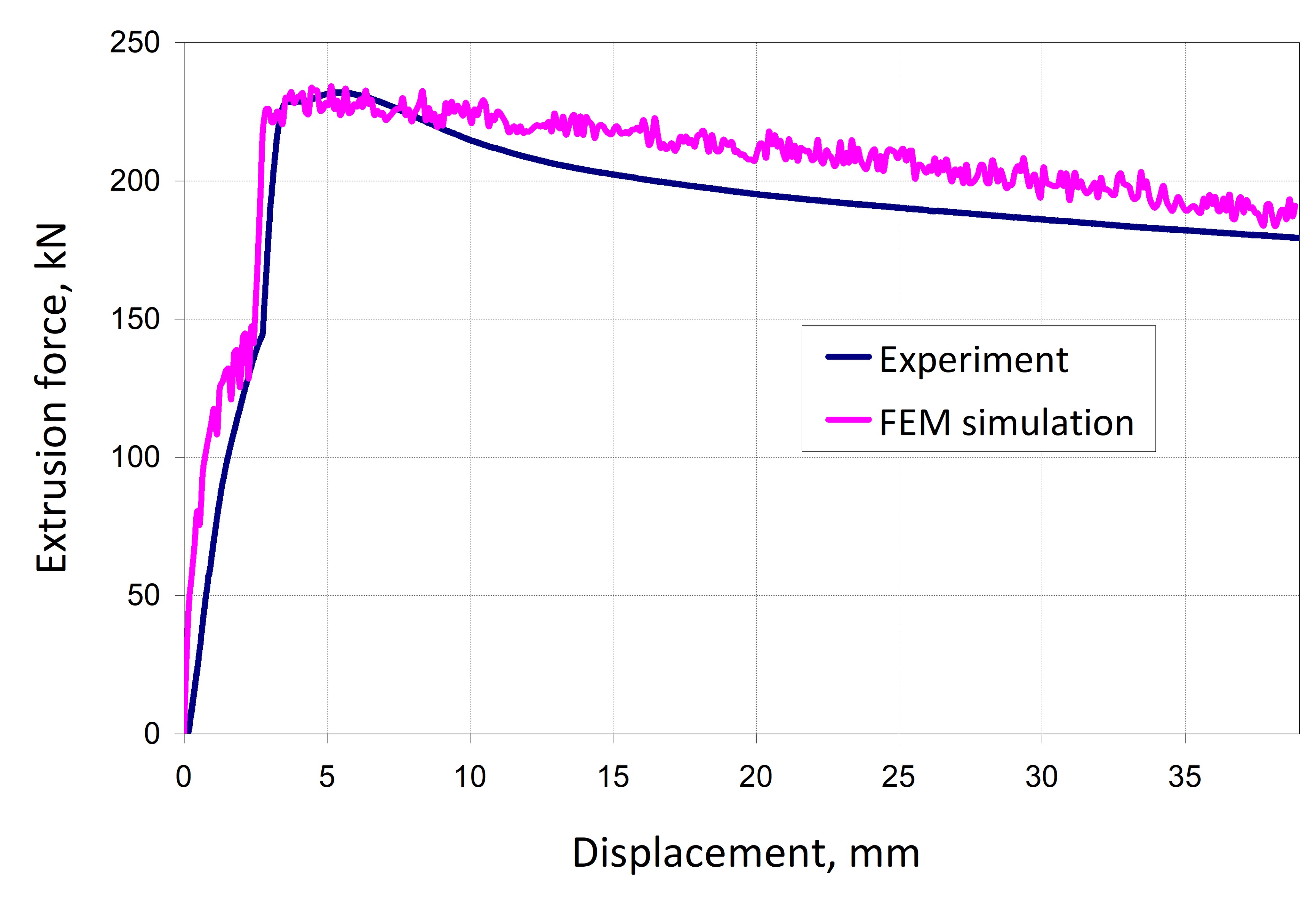
In order to verify the accuracy of the extrusion process calculations, using the developed numerical model, the relative error values were calculated from the following dependencies:
where: FFEM and FEXP are the values of the extrusion force calculated in the FEM simulation and determined experimentally. The average values of the relative error were calculated for two punch displacement ranges. The greatest convergence with the experiment was obtained in terms of the maximum extrusion force. In this case, the average value of the relative error in the first displacement of punch range from 4 to 8 mm was 1.5%. Since stress analyzes in the dies were carried out at their maximum load, obtaining a good convergence of force in this range was the most desirable and beneficial. In the second range of punch displacement from 8 to 40 mm the average value of the relative error was higher and amounted to 5.6%. However, the calculation results in the second punch displacement range were not used in these studies.
. NUMERICAL MODELING OF THE EXTRUSION PROCESS
FEM calculations of the extrusion process were performed using commercial software MARC/Mentat. The research took into account the influence of the thickness of the die walls, i.e. the die insert gm and the prestressed ring gp (Fig. 5) on the distribution and values of assembly and working stresses in the prestressed die, assuming a constant external diameter of this die. Just like at work [41], the tests were carried out for three values of the ratio gm/gp = (0.57, 1 and 1.75) and three values of assembly interference of = (0.004, 0.008 and 0.016) mm using a die insert made of steel and cemented carbide. In total, FEM calculations were performed for 18 variants of the prestressed die. The analyzed variants marked as “x”, and the corresponding values of the parameters tested are presented in Tab. 2. The tests carried out in this range of variable parameters made it possible to determine the influence of the gm/gp ratio and the amount of interference d between the insert and the ring, as well as the influence of the insert material on the value of working and assembly stresses in the compressed die. The stress measurement points in individual die elements, marked with letters A to G, are shown in Fig. 5. Both the stresses occurring during extrusion process (working stresses) and the stresses resulting from the pressing of the interference between the insert and the ring (assembly stresses) were analyzed.
Tab. 2
Compressed die parameters for 18 tested variants
| die material | gp/gm | interference [mm] | |||
| insert | ring | 0.004 | 0.008 | 0.0016 | |
steel | steel | 0.57 | x | x | x |
1 | x | x | x | ||
1.75 | x | x | x | ||
carbide | 0.57 | x | x | x | |
1 | x | x | x | ||
1.75 | x | x | x | ||
Fig. 5. Cross-section of the tested die and stress measurement points: 1 - die insert, 2 - compression ring
The following relationship was used to determine the assembly fit :

where: Dzw – outer diameter of the die insert, mm, Dwp – internal diameter of the ring, mm.
A two-dimensional geometric model of the extrusion process, which was analyzed with the assumption of axial symmetry (axisymmetric model), was adopted. An example model expanded to 3D with contact conditions of deformable bodies is shown in Fig. 6.
Fig. 6. Exemplary geometrical model of the analyzed extrusion process: 1-formed material, 2 - die insert, 3 - prestressing ring, 4 - container surface, 5 - punch surface
The material properties of the insert and prestressing ring were described using the Hooke model. For the die insert made of NC10 steel and for the compression ring, the Young's modulus and Poisson's ratio were E = 210,000 MPa and n = 0.3, respectively. In turn, for the die insert made of cemented carbide G30, E = 590,000 MPa and n = 0.2 were assumed [46]. An elastic-plastic model with nonlinear strain hardening was used to describe the properties of the extruded material. The values of material parameters, including the strain hardening curve, adopted from [45] are given in Table 1. The bilinear Coulomb model was used to describe friction. Similarly to the shear model, the friction stress limit was applied equal to the yield stress value. The coefficient of friction between the extruded material and the tool surfaces was assumed to be 0.3 [47], while that be-tween the prestressing ring and the die insert was 0.1 [48].
The deformable bodies in the numerical model were discretized using elements of class 4, type 10 - axisymmetric ring quadrilateral [49]. The finite element size of the die insert and prestressing ring was approximately 0.25 mm. Due to large geometric non-linearities, the global remeshing option was used for the extruded material. The average size of the mesh elements of the extruded material was approximately 0.4 mm. In order to make the results of numerical calculations independent of the mesh size of bodies modelled as elastic-plastic, during the development of the FEM model, the influence of the finite element ship size was analysed by densifyingthe mesh. After each compaction of the mesh, the extrusion force course was compared with the course of this force obtained with the use of the mesh before refinement. In this way, the nets were compacted until their further compaction had no greater impact on the compared parameter. The mesh was additionally compacted in the area of contact between the extruded material and the die. Calculations using static analysis were performed using the Newton-Raphson method for the implicit method. A displacement convergence criterion with a relative displacement tolerance of 0.1 was used. The time step size was 0.1 s which corresponded to a punch displacement of 0.1 mm. The Huber-Mises isotropic plasticity condition and the Prandtl-Reuss law of plastic flow were used.
. CALCULATION RESULTS AND THEIR ANALYSIS
For each analyzed variant, readings were made at seven measurement points A-G (Fig. 5) of the initial circumferential stresses occurring after the assembly of the die insert and the ring, as well as the working circumferential stresses occurring during the extrusion. The same meshes were used in all calculation variants. In order to obtain an unambiguous reading of the stress value, the measurement points A-G were set appropriately in the nodes of the finite element mesh. The numerical simulation was carried out in two stages. In the first stage, the press-fit connection of the insert and the prestressed die ring was modelled. In the second stage, after obtaining the assumed value of the press-fit, the extrusion process was modelled. The measurement of the initial (assembly) stresses at individual points of the die was made after the first stage of modelling, i.e. before the start of extrusion. In turn, the measurement of the working stresses was made in the second stage, always after 1/3 of the volume of the input material had been pressed out. By using an appropriate die design by changing the thickness of the die insert and the compression ring, as well as by changing the die material, it is possible to influence the values of the maximum circumferential stresses occurring in the tool during extrusion. Fig. 7 shows the dependence of the value of initial circumferential stresses after assembly at the measurement points (A, B, C and D) located in the area of the die insert, depending on the gm/gp value, die insert material, and the interference value.
As it can be seen from Figure 7, for all measuring locations of the die insert, with in-creasing interference, favorable circumferential compressive stresses occur. Irrespective of the insert material, at all analyzed measurement points (A-D), their value is the greater, the greater the assembly interference. At the same time it should be noted that the values of circumferential compressive stresses after assembly are in all cases more favourable for the cemented carbide insert than for the steel insert. The quotient gm/gp also has a significant impact on the assembly stress values. The data in the graphs (Fig. 7) shows that at all measurement points (A-D) with the increase in the value of gm/gp, the value of favourable circumferential compressive stresses decreases. This tendency exists regardless of the size of the assembly interference.
Hence, in the considered spectrum of parameters, the best result, manifested by the highest value of circumferential compressive stresses in both die insert materials, was obtained for the highest value of assembly interference and the lowest value of the gm/gp quotient. For instance, at point A for the gm/gp = 0.57, the increase of the mounting interference from (0.004 to 0.016) mm caused an almost 4-fold increase in the beneficial circumferential compressive stress in the cemented carbide die insert and only slightly smaller in the steel insert. On the other hand, an increase in the gm/gp from 0.57 to 1.75 resulted in the use of the highest interference value ( = 0.016 mm) by approx. 2.6-fold reduction in the favourable peripheral compressive stress in the cemented carbide insert and over 2.1-fold decrease in steel insert. In the tests carried out, for both die insert materials it is unfavorable to use the lowest interference value, i.e. 0.004 mm and the highest gm/gp = 1.5.
Considering the ring, the circumferential assembly stress is tensile and increases as the interference value grows. It should be noted that, in the range of tested impacts, at all E-G measuring points of the ring slightly higher values of these stresses occur in the variant with a cemented carbide insert compared to the use of a steel insert. At the same time, the difference in the value of these stresses for both variants of the insert material grows with an increasing value of the mounting interference. For instance, increasing the pressure from 0.004 to 0.016 mm causes at point F about a 4-fold growth in the value of circumferential tensile stress in the compression ring when using a steel insert and only slightly larger when using a cemented carbide insert.
Fig. 7. The value of initial circumferential stress at points A-D of the die after assembly depending on the value of g m /g p for the steel and cemented carbide insert and three mounting interference = (0.004, 0.008, 0.016)
Fig. 8. The value of initial circumferential stresses at points E-G of the ring after assembly depending on the g m /g p values for the steel insert and the insert made of sintered carbide and three mounting interference = (0.004, 0.008, 0.016)
The graphs presented in Fig. 8 show that the impact of the gm/gp parameter on the value of circumferential tensile stresses in the compression ring after assembly is small. Fig. 9 illustrates the values of circumferential stress under load at A-D measuring points belonging to the die insert during extrusion.
During extrusion as a result of tool loading, circumferential tensile stresses arise in the die. When using pre-stressed dies, the value of these stresses in the die insert is reduced by the value of the initial assembly stresses. Therefore, the higher the values of the circumferential compressive stresses in the die after assembly, the more advantageously as the smaller the values of these stresses during extrusion are. This tendency occurs at all A-D measuring points of the die insert. For instance, at A, the value of circumferential tensile stress decreases as the value of the interference increases, which is advantageous.
Fig. 9. The value of working circumferential stresses at points A-D of the die during extrusion depending on the g m /g p values for the steel insert and the sintered carbide insert and three mounting interference = (0.004, 0.008, 0.016)
For the largest considered interference, for the gm/gp ratio of 0.57 and 1, the stress values are negative. It follows that the value of the tensile circumferential working stresses in the die is lower than the value of the circumferential compressive stresses after the installation of the insert and compression ring. It can be seen that the gm/gp quotient has an important influence on the value of working stresses in the die insert. Moreover, the lower the value of this quotient, the better (Fig. 9). It should be noted that despite the fact that assembly stresses at AD points for all the interference values were slightly more favourable for the cemented carbide insert (larger negative values of circumferential stresses) (Fig. 7), under load (Fig. 9) more favourable stresses, i.e. with lower values, occur in a steel insert. This means that the use of a compression ring due to operating stress is more effective for a die with a steel insert. In the case of cemented carbide insert, despite the favourable values of assembly stress under load as a result of much greater elastic rigidity of cemented carbide compared to steel, much less operating stress is transferred by the steel compression ring than when the compression ring, and the die insert are made of material with the same elastic stiffness ex-pressed by the Young's modulus of elasticity.
The values of working stresses at the points EF presented in the diagrams (Fig. 10) are the confirmation. It can be seen that, regardless of the ratio of gm/gp at all analyzed EG points for impressions with 0.004 and 0.008 mm, the value of circumferential ten-sile stress in the compression ring during extrusion is higher when a steel die insert is used, which means that the compression ring carries a higher load than in when a cemented carbide insert is used. Taking into account the obtained results concerning stresses in the ring, its effectiveness can be seen to increase with the increase of the assembly interference. On the other hand, there was no significant effect of the gm/gp ratio on the working stresses of the ring.
Stress distributions and gradients on the longitudinal cross-section of the die insert and the compression ring are also of great importance from the point of view of tool durability among those considered. Selected stress distribution results are shown in Figures 11 and 12. For both the die with a carbide insert and the steel insert, the circumferential tensile stresses in the insert and the ring after assembly (Fig. 11) are relatively uniform (i.e. without significant gradients) and their distribution depends on the gm/gp ratio and to a much lesser extent on the insert material.
If we take into account the variant with load (Fig. 12), the stresses in the insert and the ring are more inhomogeneous with areas of different concentration. The test results indicate that the highest stress concentration occurs at the insert corner and in the area of the inner corner of the compression ring.
In engineering practice, when selecting the interference in the case of an insert and a compression ring made of steel, it should be ensured that during loading, the smallest possible stress gradients between the insert and the ring occur. In addition, the values of circumferential tensile stress in the ring do not exceed the allowable values. Therefore, it is important to search for solutions, including geometric ones, to reduce stress gradients as adversely as possible.
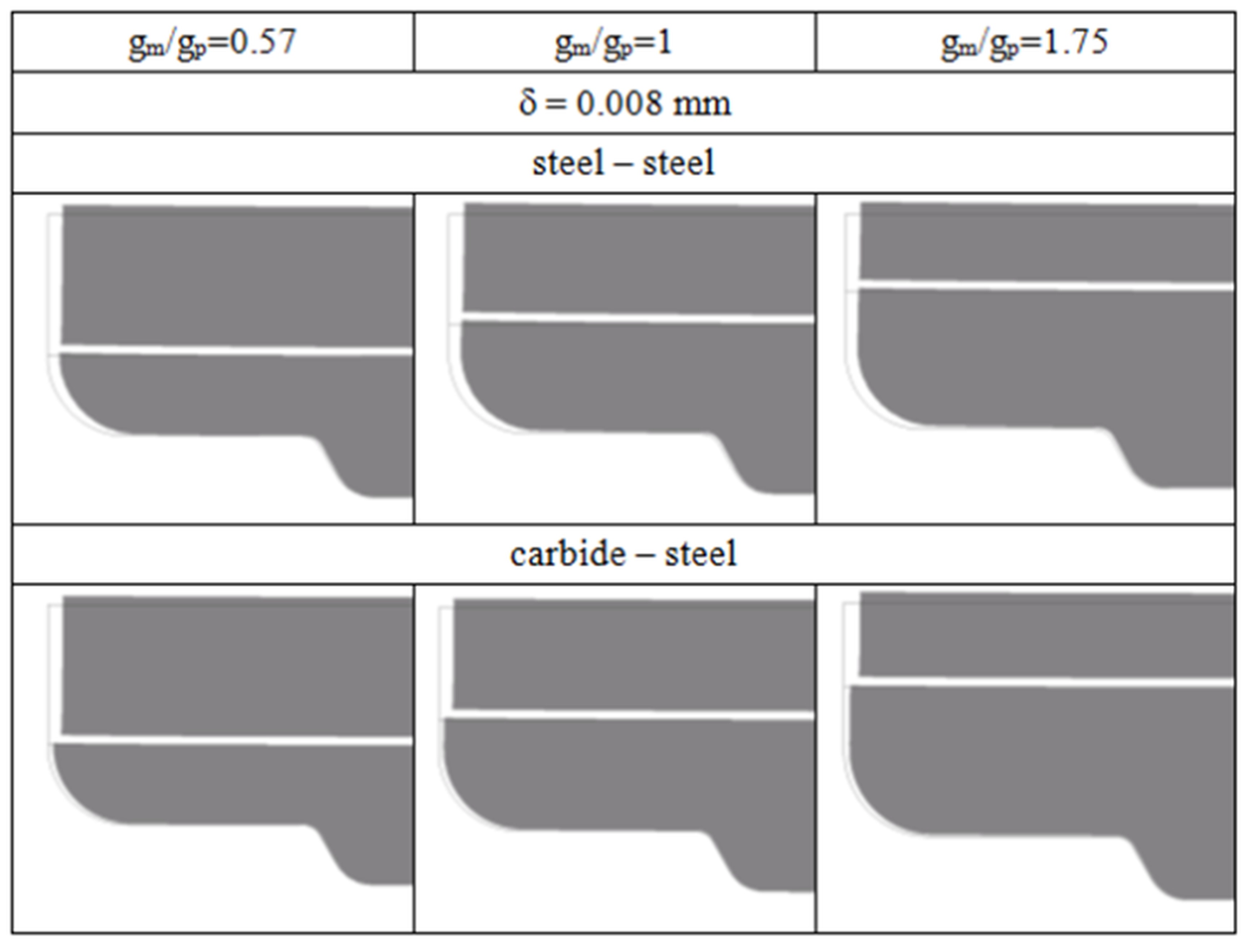
A very important parameter from the point of view of product quality is the deformation of shaping tools under load. Exemplary deformations of a die with a steel insert and sintered carbide under load, using the 0.008 mm interference and three tested values of the gm/gp ratio are presented in Figure 13. In the case of a steel insert, due to the lower elastic stiffness of this material compared to carbide both in the radial and axial direction is greater than the deformation of the cemented carbide insert.
Fig. 10. The value of the working circumferential stresses at points E-G of the ring depending on the g m /g p values for the steel insert and the sintered carbide insert as well as three mounting interference = (0.004, 0.008, 0.016)
Fig. 11. Distributions and values of circumferential stresses in the die after assembly with = 0.008 mm interference for three g m /g p values of 0.57, 1 and 1.75 and for two die insert materials
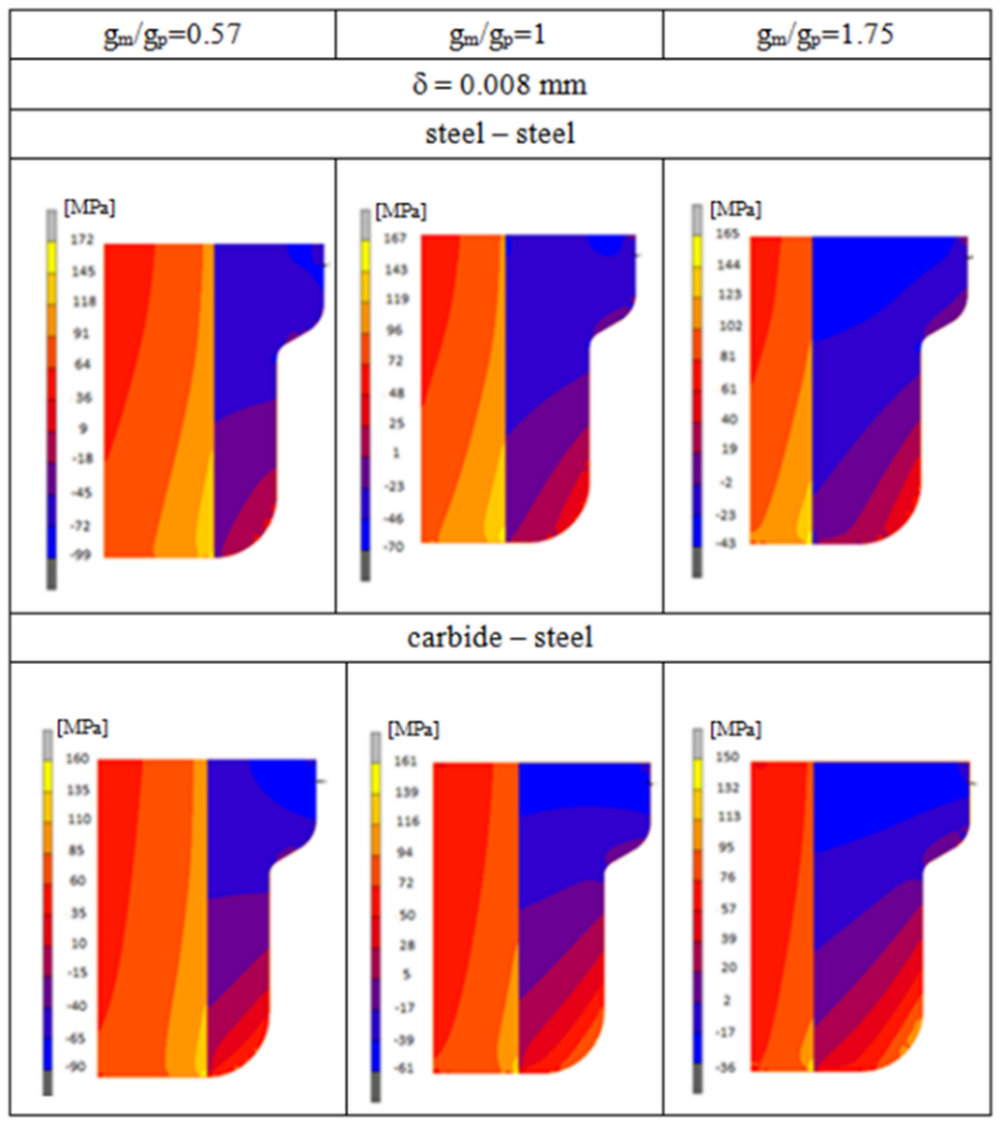
Fig. 12. Distributions and values of circumferential stresses in the tool with an interference fit of = 0.008 mm for three g m /g p values of 0.57, 1 and 1.75 for a steel and cemented carbide die
As shown in Fig. 13, the deformation of both the steel insert and the carbide insert is greater, the greater the ratio of gm/gp. In addition, in the case of a die with a steel insert, the elastic deformation of the ring and the insert in the axial direction is the same due to the equal Young's modulus of the insert material and the ring. However, for a die with a cemented carbide insert, one can see the difference in the amount of axial deformation of the insert and the ring in the form of a step between the face of the insert and the ring from the input side of the extruded material. The reason for the uneven displacement of the face of the insert and the ring is in this case a significant difference in the value of Young's modulus, which for the material of the insert is more than 3 times greater than for the material of the ring.
. CONCLUSIONS
The paper presents the results of stress analysis in dies with a steel insert and sintered carbide compressed with one ring. Three design solutions of the die were taken into account, differing in the ratio of the wall thickness of the die insert to the wall thickness of the compression ring gm/gp = (0.57; 1 and 1.75) while maintaining a constant tool diameter. The tests included three values of the assembly interference ( = 0.004; 0.008, 0.016) mm. The influence of the type of insert material and the quotient of the insert wall thickness to the compression ring thickness, as well as the size of the interference between the insert and the compression ring on the value of assembly and working stresses in the die were determined. The degree of influence of the tested parameters (interference value , gm/gp ratio and type of die insert material) on the distribution and level of circumferential stresses in the die prestressed with one ring with the use of both inserts was determined. It was found that the size of the interference fit and the quotient (gm/gp) had the greatest impact on the reduction of the working stresses in the die insert, while the type of die insert material had the smallest effect.
The investigations showed the significant influence of all tested parameters (i.e. the size of the mounting interference, the type of die insert material and the ratio of gm/gp) on the level of circumferential stresses in the die both during assembly and working during extrusion.
In the variants considered in the research, the use of assembly interference results in the appearance of favourable initial circumferential compressive stresses in the die insert material. Their value shifts towards negative values as the mounting interference increases. However, the intensity of growth decreases as the gm/gp value increases.
The research has shown that the geometric configuration of the die, expressed by the gm/gp ratio, has a very positive effect on the value of circumferential stresses in the die insert. However, as the value of this parameter decreases, the favourable stresses in the insert increase (the most favourable gm/gp ratio was 0.57).
The use of the pre-stressed die with a steel insert is slightly more effective due to the occurrence of lower values of peripheral stresses during extrusion than in the dies with a cemented carbide insert, despite the fact that assembly stresses were more favourable for a die with a carbide insert. The slight reduction in benefits in the form of reduced working stress in the case of the die with a carbide insert compared to the die with a steel insert is due to the significant difference in the longitudinal modulus of steel and cemented carbide, and thus different elastic stiffness of these materials.
The greatest impact on reducing the value of working stresses in the die insert has the size of the interference and the quotient (gm/gp), while the smallest type of material of the die insert. In turn, the type of insert material has a significant impact on the amount of die deformation under load and wear resistance. In this respect, the prestressed die with the cemented carbide insert falls more favourably.